 Mario Frei
It was quite an adventure to design, produce, and deploy approximately 150 sensor nodes. Below are some of the ‘lessons learned’ from this experience.
- Simplicity
- In the beginning, we had many features in mind to be included, e.g., SD card logging on the sensor node, collecting multiple measurements, and sending them bundled together to save energy, etc. A lot of these features were meant as a backup measure in case that something didn’t work out, e.g., underperforming mesh network, or an insufficient battery lifetime. However, these features added quite a bit of complexity in the PCB design and code and weren’t or couldn’t be used later on. Furthermore, these features also added quite a bit of cost.
- Cost
- Even though the cost of the sensor network was within budget, it could be 50% lower. The most expensive components on the main module are the battery (35%), the XBee module (25%), RTC (8.7%), and the SD-card socket (5.5%). These components make up 71% of the main module cost. XBee modules are simple and robust but also expensive, and there is no bulk pricing. Switching to RFM69 radio modules could reduce the price significantly. The RTC and SD-card socket could be omitted without replacement. Finally, batteries became already much cheaper just over the course of this project. So waiting for the prices to drop even further seems to be a feasible option. Alternatively, one could also use alkaline batteries. The sensor network is intended to be deployed for several months. By the end of the deployment will be collected and refurbished. Hence, a battery change wouldn’t be too inconvenient compared to sensors that are intended to stay in place for several years.
- Robustness
- For most applications, it is essential to have somewhat continuous time-series data. Hence, we should have put more effort into ensuring it. It turned out that the gateway was the most vulnerable member of the message chain from the sensor to the webserver. However, I am still not aware of methods to test varying levels of reception in the cellular network in a repeatable and non-cumbersome way, e.g., walking around with the whole test equipment is not much fun (or feasible).
- Automation
- Initially, the goal was to achieve a high degree of automation. However, there were constant issues, with window sensors, energy meters, and the gateways. These issues drained the focus from other tasks and also caused additional issues with automation, e.g., how to deal with the gaps in the data, or how to find a period with minimal gaps, etc. I wasted a lot of time on the automation of processes that shouldn’t be needed in the first place. In hindsight, I would rather focus first on the robustness of the overall data collection processes. Once the systems work somewhat smoothly and reliably, it’s quite easy to focus on automation.
- Message format
- The sensor data is re-formatted several times during the transmission, e.g., sensor module -> main module, main module -> gateway, gateway ->web server. We could have saved some work and reduced the complexity by adhering to a single format through the communication chain. The only drawback would have been the loss of some flexibility, which was never used in the first place.
- Practical things
- The battery connectors seem fine at first glance. However, after countless unplugging and re-plugging these kinds of connectors, I’d like to find another solution. I am wondering whether holders for 18650 cells would be a better solution.
- The wired connectors between the main module and sensor module are somewhat expensive, time-intensive the manufacture, awkward to handle, and somewhat prone to failure. Hence, they should be replaced through a different solution, e.g., right angle, surface-mount pin headers.
- Currently, the power supply cable for the main module is attached to the bottom half of the sensor node housing. If the power supply or the housing is damaged, a soldering iron is needed to remove the power cable from the housing. This should be improved, either by changes to the design of the enclosure and/or through a different power supply plug.
- An RSSI indicator would be a helpful tool during deployment. This could be a handheld device that indicates the RSSI level or it could be implemented in the web-interface. Such a tool could help to place route nodes.
- During data processing, measured data had to be merged frequently with metadata, e.g., room number, floor number, building number, etc. It might be helpful to add this metadata to the web interface, where it could be added during the sensor deployment. Later, the measured data could be retrieved with the associated metadata, without the need to keep track of multiple spreadsheets.
- Visualization
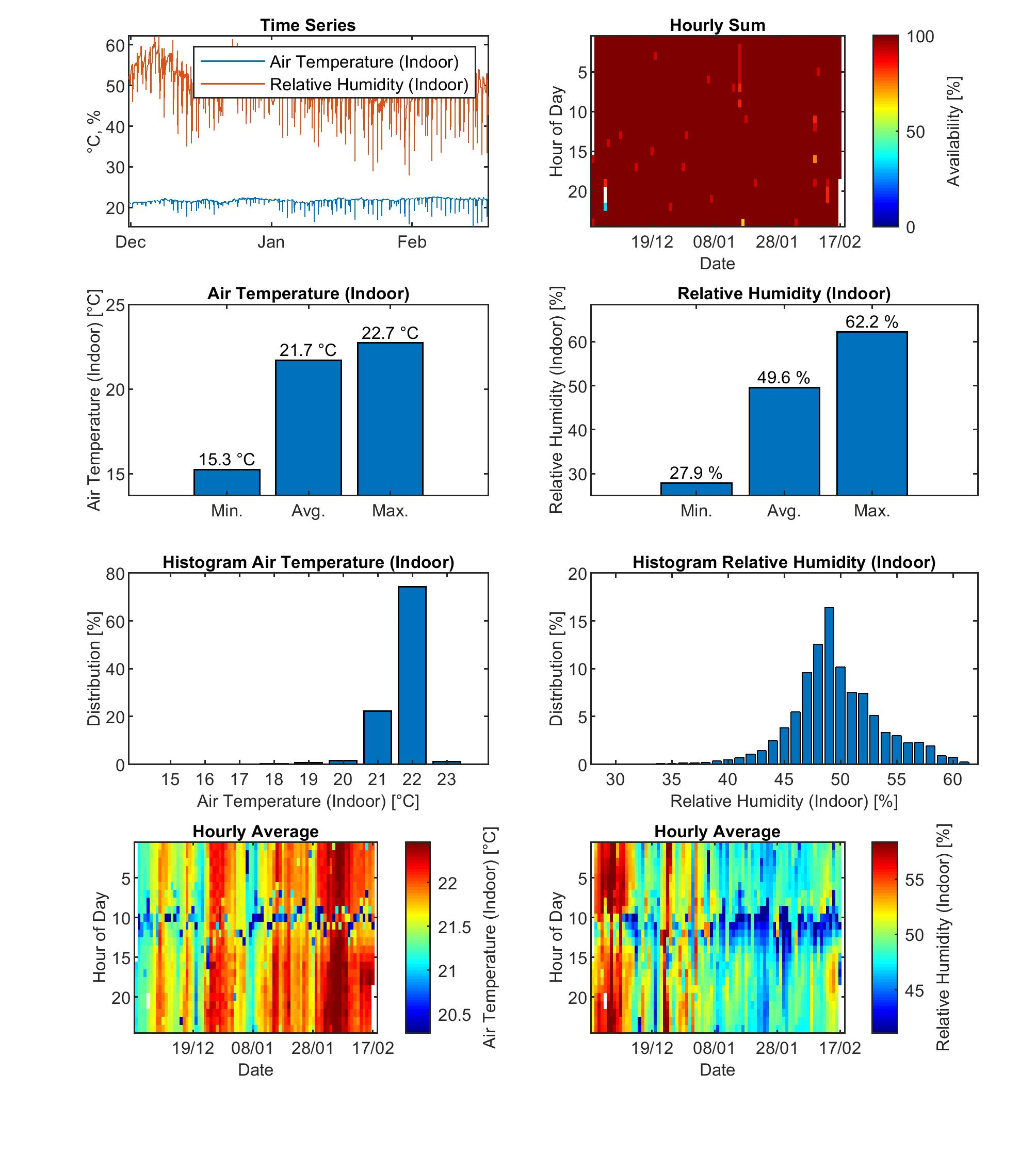
- The overview plots from the last two project logs were quite helpful in getting a quick first impression of the performance of the sensor nodes. However, to see whether the measured data is meaning full, we also used overview figures for single sensor nodes. These figures included the time series data, histograms, and raster plots. On example is shown below:
![]()
Discussions
Become a Hackaday.io Member
Create an account to leave a comment. Already have an account? Log In.