 Kevin Kadooka
This is my first attempt at building a digital camera. When I set about to do this, I had a few requirements in mind:
- Portability: It should not be tethered to a laptop or power supply, easily stuffed in a backpack
- Large frame size: Simply put, none of this small format 1/1.8" sensor BS. Big frame and fast(ish) lens for slim depth of field.
- (Relatively) Inexpensive: Less than $1000 all told (fingers crossed on this one).
- (Relatively) Good image quality: It should produce images that you won't be ashamed to print on a postcard.
- Mostly open-source: Should contain very few parts that have to be ripped out of something else - making an exception for the lens here, because optical design is not in my wheelhouse
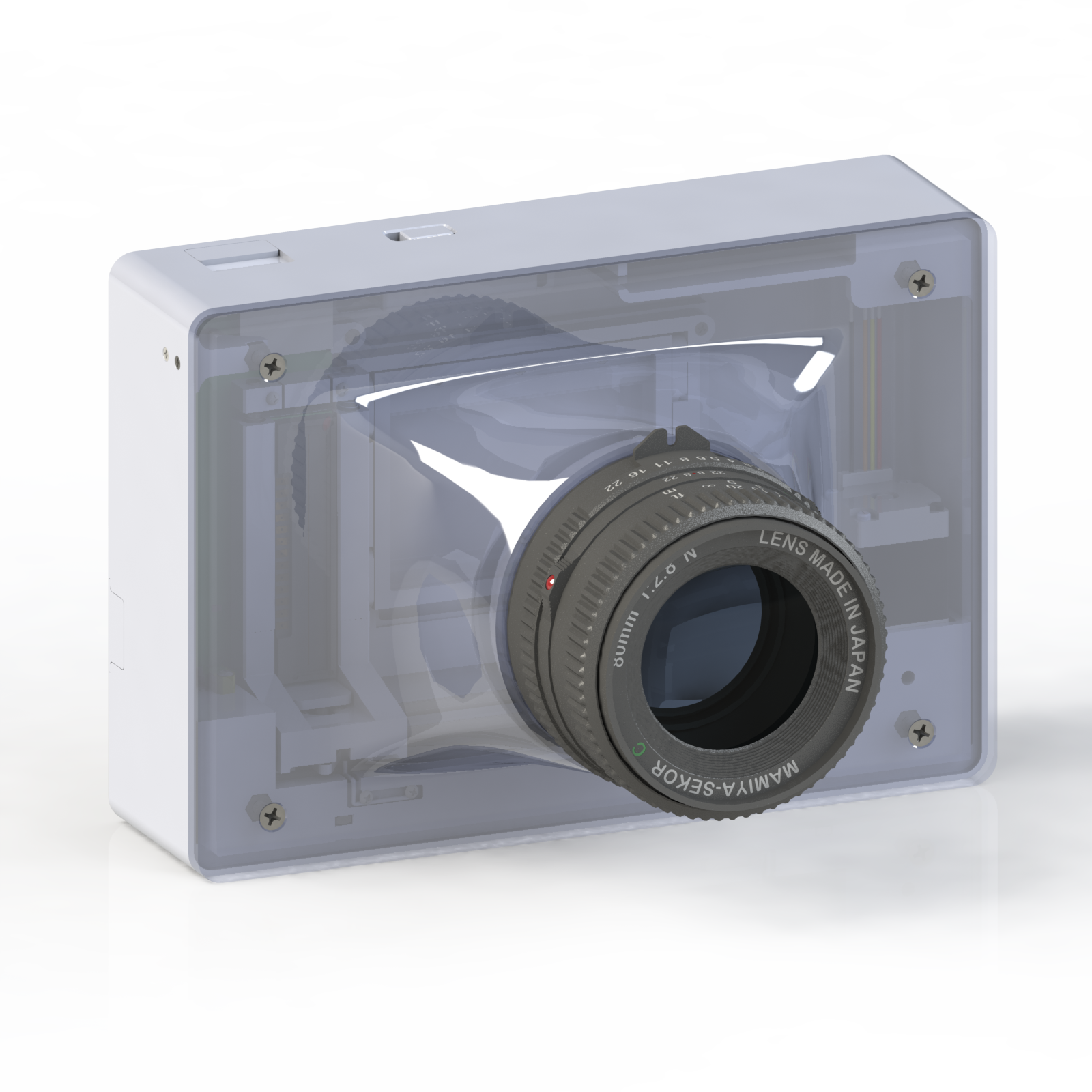
Considering these requirements, I settled on the "scanner camera" design, which true to its name, "scans" a linear photodiode or CCD array across an image plane to produce a 2D image. There's really no other cost-effective way to produce medium-format digital images, unless you have a silicon nanofabrication facility in your backyard. So, over the course of a few weeks I whipped up an initial concept for what I'm calling "SPUD" (which refers to the "potato-like" quality of the images it will produce) and it also stands for the "superfluous perpetually useless device").
It will be based around the (grayscale!) TSL1406RS linear photodiode array, which consists of 768 light-sensitive pixels with 63.5 micron pitch. The linear array is scanned across the image surface using a linear stage and a stepper motor. The viewfinder is basically a piece of ground glass that swings into place. All of the motion control, image processing, etc, will be driven by a Teensy 3.2.
I am definitely skipping a few steps here (and I would like to elaborate on the mechanical design at a later date!), but earlier this week I received the TSL and Teensy in the mail, and took to breadboarding the thing to see how it would tick.
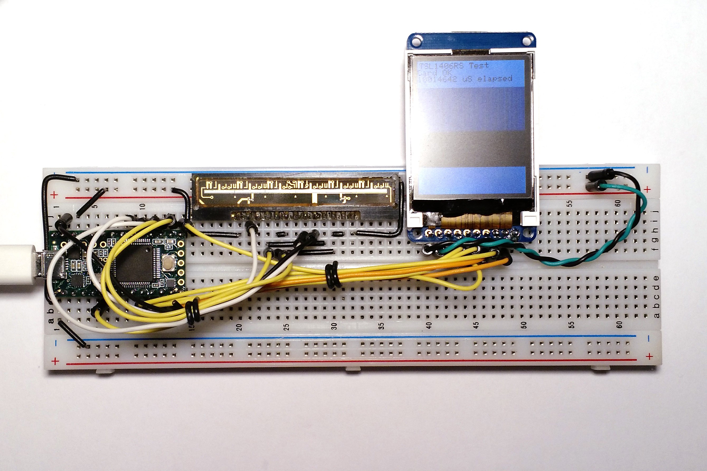
Here's what it looks like on a breadboard. I'm also using an Adafruit 1.8" TFT screen to display the imaging parameters, image preview, and to store the image data as a PGM (portable gray map) file on a microSD card. Going on a tangent here, I decided to use the PGM format because - well, I'm too lazy to write up the complicated BMP header. Also, BMP's don't handle 16 bit grayscale values. JPEG and PNG compression is not something I would like to attempt either.
So far, the stuff on the breadboard can:
- Capture a progression of line-scan images, and save them to a PGM file on the uSD card.
- Produce a small preview of the image on the LCD.
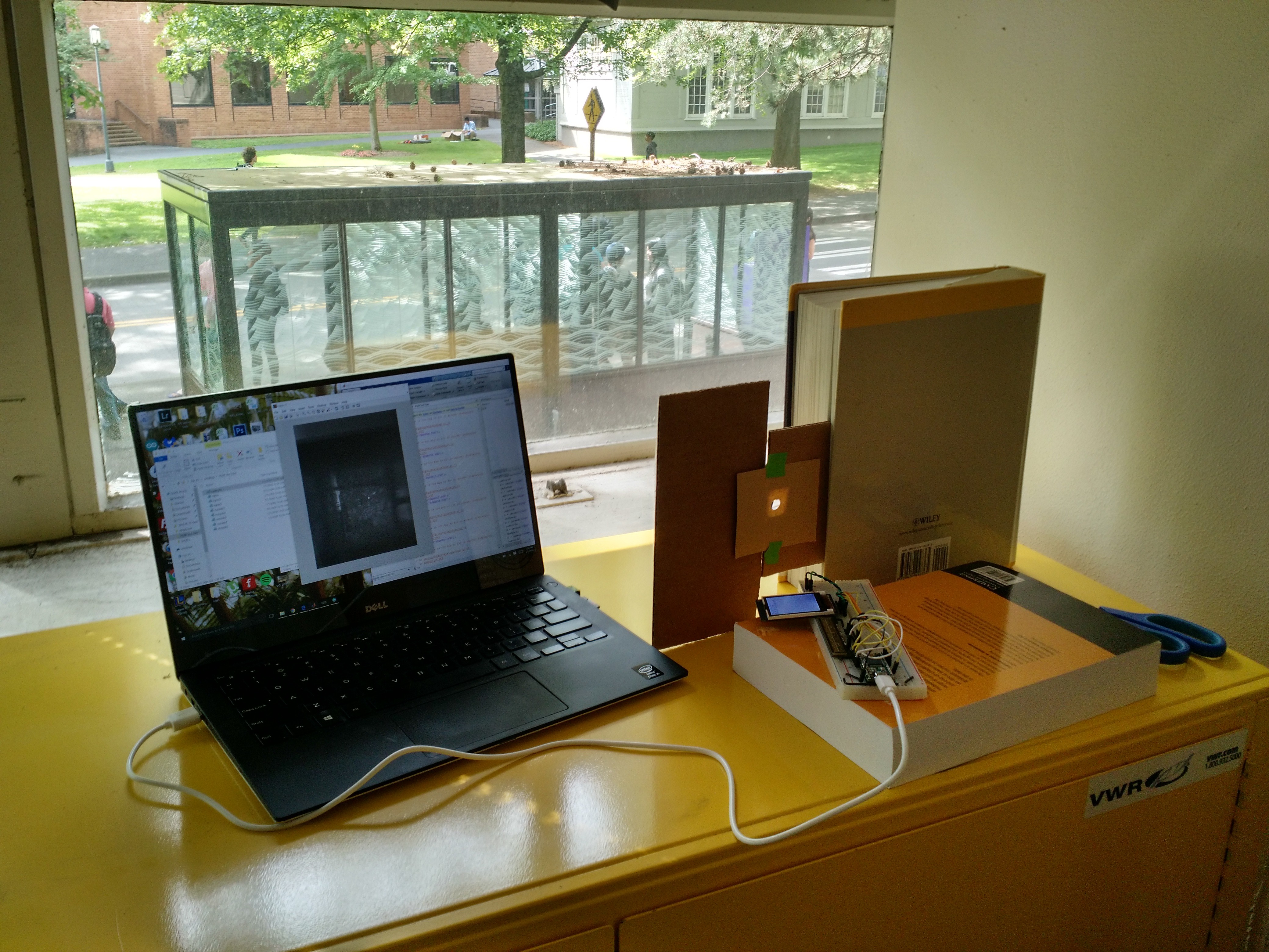
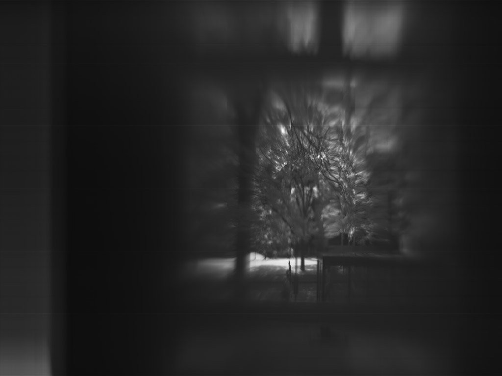
I haven't yet put everything on a linear stage, so there's no way to "scan" the sensor across an image plane. However, leave it to an impatient engineer to figure out a way to make it work (temporarily, and rather poorly). By scanning the sensor across the image projected by a simple double-convex lens (f = 40mm), I can make a wobbly-looking image with a lot of spherical aberration (from the simple lens).
Not bad! But also, not good. Still you can kind of tell what's going on in the image. The contrast is pretty poor, because of significant light leakage. It can only get better from here!
Discussions
Become a Hackaday.io Member
Create an account to leave a comment. Already have an account? Log In.