 Radu Motisan
I tried to detect noise pollution levels in HW 104 but failed due to improper circuit design. Back to the drawing board, I opted for the MAX4466 where some know how was already available, thanks for the efforts of @ladyada / @limor . With this approach, results were immediate:
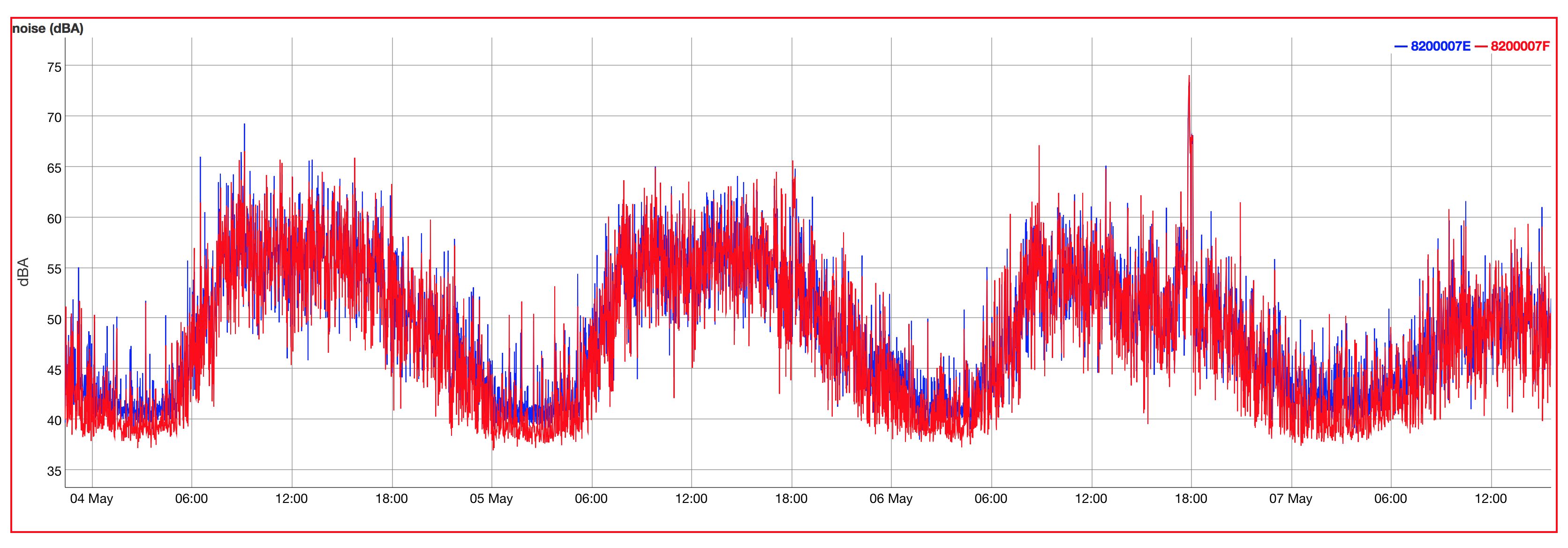
The chart shows noise levels as recorded by two A3 units operating alongside, for a few days. The elevated values are due to traffic noise, more prominent during the day. I used a sound-meter for some calibrations. The data is exported in raw format, and calibrations are done on the sever, so I can have more control over the output. But all in one, having identical readings from two separate hardware units was a nice achievement.
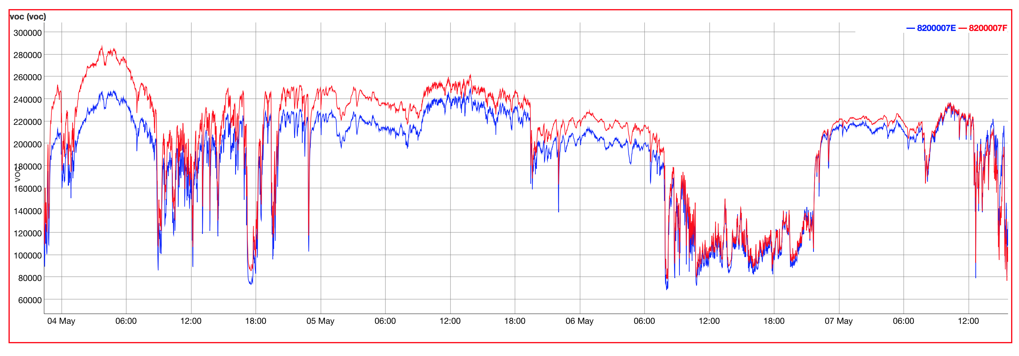
As for the new VOC sensor, I tested the MP503, a similar tech to the previous GM502B, but due to bigger size it was more resilient to soldering and I was able to install it, without affecting its initial performance. Again, two units were tested, and the readings went in tandem.
Similar to the BME680, these sensors have a simple principle. A heater is placed near a metal oxide semiconductor. If the air is contaminated with various substances (as those belonging to the VOC family), various REDOX chemical reactions will take place, affecting the semiconductor conductivity.
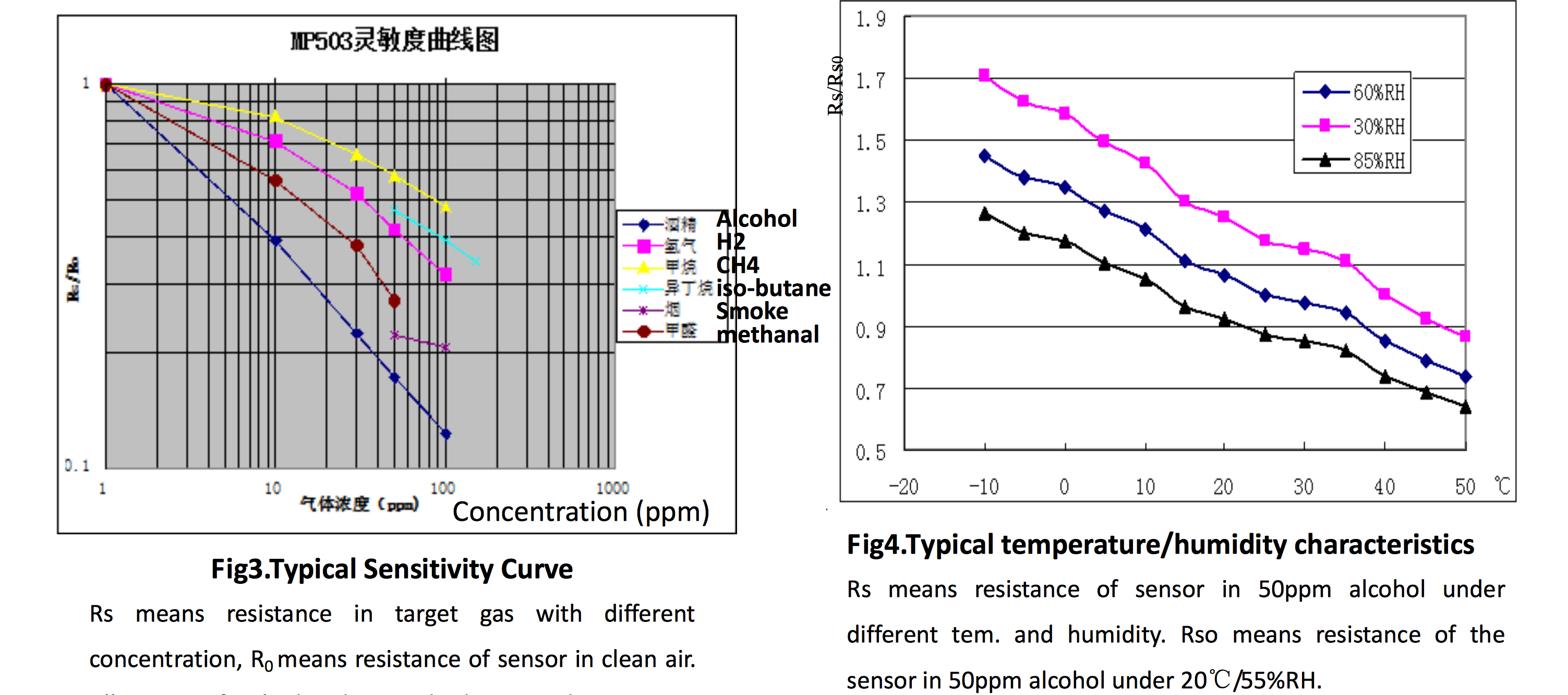
What happens is that if the air is more contaminated, the sensor will become more conductive. So on a clean air we will read a higher resistance, while a polluted air will bring the sensor resistance down. This is how the ohm are linked to air quality on these kind of sensors. The only issue is the readings will fluctuate with environmental temperature and humidity, so for absolutely perfect readings, the data will have to be calibrated against the two, according to the chart in the datasheet. A linear function will do it nicely.
Discussions
Become a Hackaday.io Member
Create an account to leave a comment. Already have an account? Log In.