Lee Djavaherian
-
TrillSat After Two Years
01/27/2021 at 09:15 • 0 commentsA couple of weeks ago, I received a nice comment from one of the community judges for the Hackaday contests and was amazed when I also noticed that he added TrillSat to his How to Enter a Project into a Hackaday Contest page as an example of what to do to make one's project stand out (excerpt below):
"We really, really like projects that encourage citizen science, or that could be used for real research and development!
A few projects come to mind, even after the thousands of projects I've seen . . . , the TrillSat, . . . Why did these score so well? They fit their category; they were innovative or creative; they solved an actual problem or enabled science to be done; the projects were completed, and had working examples."Thank you! I also noticed that yesterday one of the HaD writers published an interesting article on the capstan equation and capstan drive, a simple machine that is often underappreciated and core to the operation of TrillSat.
I have continued improving TrillSat since my last log entry on 9/7/2018 and have posted summaries below (hardware and software updates, bug fixes, the radio system, motor drive, gyro, and planned updates).
Some of the highlights are:
- Built secondary station TRILLSAT-G and recorded video of a successful over-the-air test of all of TRILLSAT-1's packet radio systems (including my experimental APRS "stupor" method)
- Tested the BLDC gyro at 1800 RPM (5 times faster than the original video)
- Extracted the craft's equations of motion and began writing a paper on the subject
- Designed a "camstan" to act as a continuously-variable transmission
- Added the Delta-v Motor Drive System which incorporates my mathematical model of its torque curve
The primary obstacle preventing me from testing everything outside is that tricky motor drive. By overloading a single motor to maximize the number of functions per motor while minimizing the number of sensors, I was hoping to skirt by some of the mathematical complexity of the multiple joints and links in an articulated robot, but because of the axes of rotation, the dynamic torques, and the precision that I require, I unwittingly created something similar but in rotational form. It turned out that my analogy of orbital mechanics was much closer than I had realized two years ago, which is wonderful, but it's not easy to keep the wobbly craft on my idealized "orbit", especially when it is under feed-forward, dead-reckoning control most of the time (which is why I had to build the Delta-v system).
Hopefully, I'll get a successful indoor test of the craft moving "smoothly and accurately" along the tether, two traits that are critical for both long-distance locomotion and aligning the solar panel. Whether it succeeds or fails, I plan to record video of its first Delta-v test this year.
It's difficult but exciting; my Kitty Hawk moment is near.
Hardware updates:
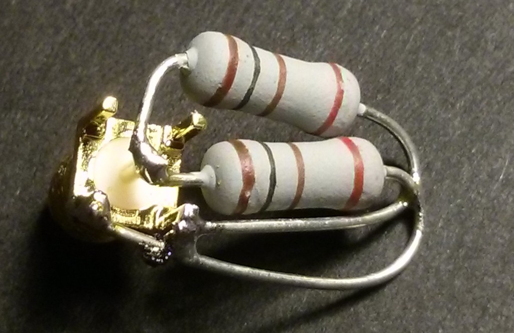
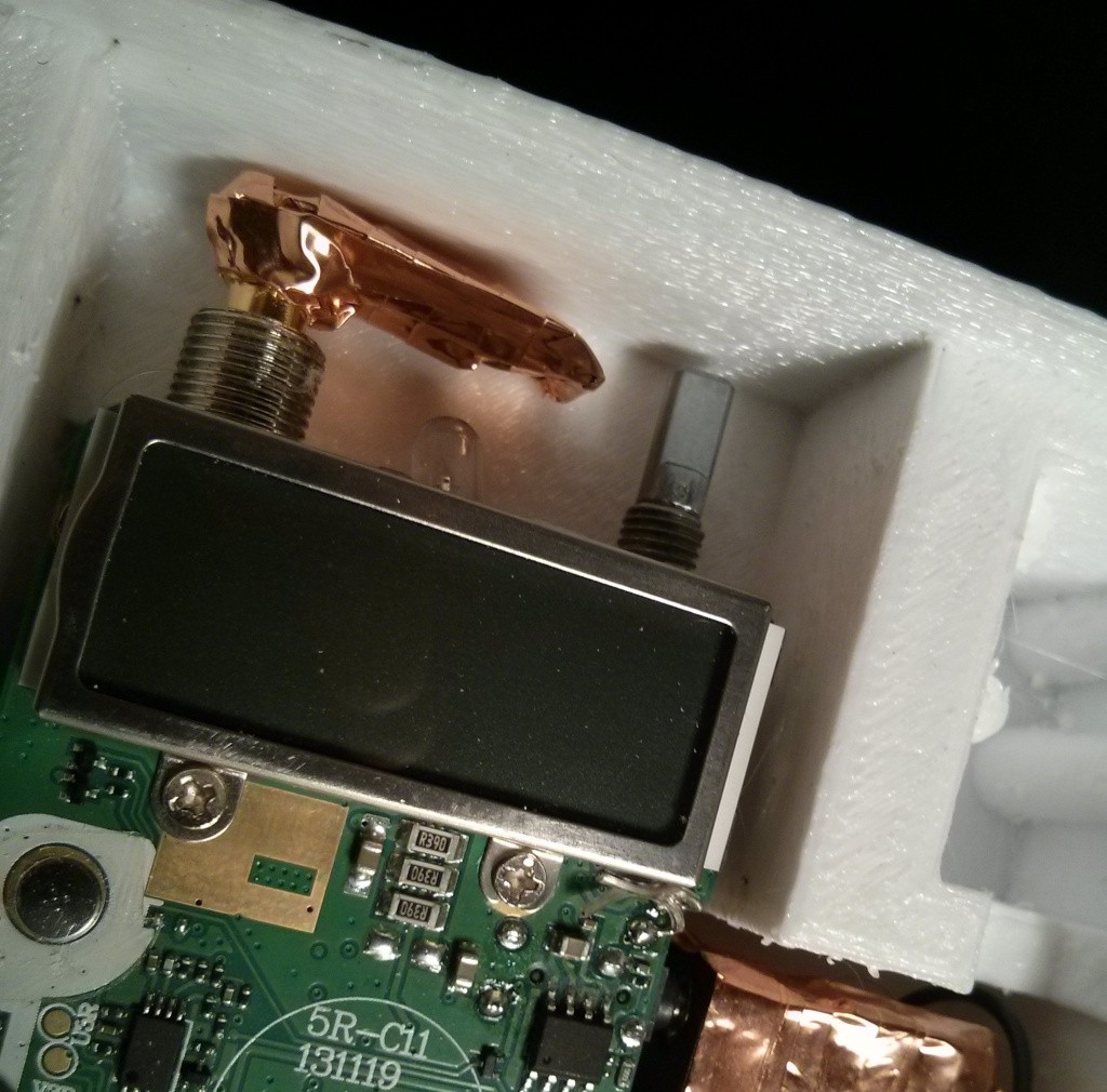
Built a low-profile 50-ohm dummy load to barely fit inside the TRILLSAT-1 radio box using two 2-watt, 100-ohm, non-wirewound resistors in parallel for 50 ohm, 4 watts to match the max output of the UV-5RA.
![]()
It was insulated with Kapton tape and has a copper foil shield to ground.
![]()
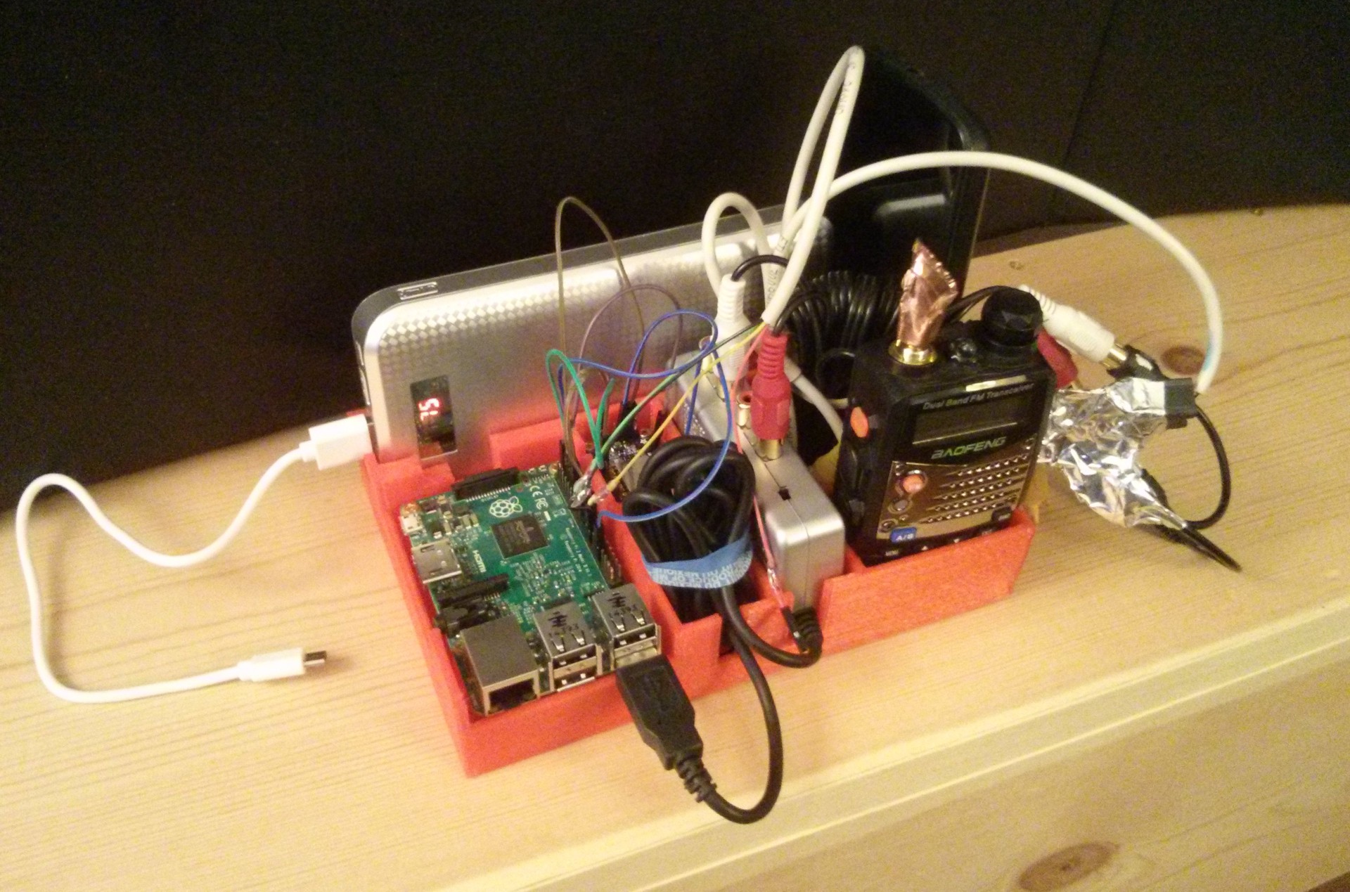
Built TRILLSAT-G (G for groundstation), a self-contained, mobile system for proof-of-concept testing of TRILLSAT-1 with no reliance on power grid, Internet, or cell infrastructure whatsoever during testing. I had to rework the software to create a groundstation mode, build another dummy load, add another ESP8266, USB powerbank, and designed and 3D printed a holder tray. My first version was built around the Pi 2 ARMv7, but I later moved it to a Pi B+ overclocked to 1 GHz, which matches the ARMv6 of TRILLSAT-1.
![]()
Replaced the 2016 Pi Zero W board on TRILLSAT-1 with a 2017 one which fixed GPIO 21 that I damaged years ago.
Replaced the MicroSD card in TRILLSAT-1 with a brand new one and rebuilt the OS and software again on the new card. It turned out that the primary reason I kept having corruption with my ext4 file system over the years, even after I re-installed it and ran fsck, was due to its peculiar failure mode, retention errors when the flash medium on this old, heavily used card apparently lost charge, the data corrupting only after I left it powered off for several weeks.
I realized that the 1.8 K ohm I2C pull-up resistors on the Pi Zero W were offline when the Pi was powered down, and neither the ESP, LIS3DH, nor ATtinys had their own I2C pullups. I tried to add my own pullups but the Pi GPIO passive protection diodes sink them directly to ground if the Pi is powered down, so I investigated tri-state transceiver chips to isolate the bidirectional signals, but then realized the Pi Zero in its reset state (where the reset, or "RUN", line is held down continuously but the power is still applied) allows the pullups to work and uses less power, a viable way of keeping the Pi board alive, yet in a coma to keep those I2C pullups enabled. This was very important so the EPS8266 could control the ATtinys if the Pi went down in an emergency situation.
Connected the ATtiny reset lines to the ESP8266 in case the Pi went down but had to add external pullups since the high impedance INPUT mode in NodeMCU on the ESP8266 drew just enough current to sink the weak pulldowns of the Pi Zero W on my ATtiny reset lines, which caused the inverted-logic transistor base to flip high under RFI conditions (such as during motor use when I often need to perform emergency shutdown), triggering a reset.
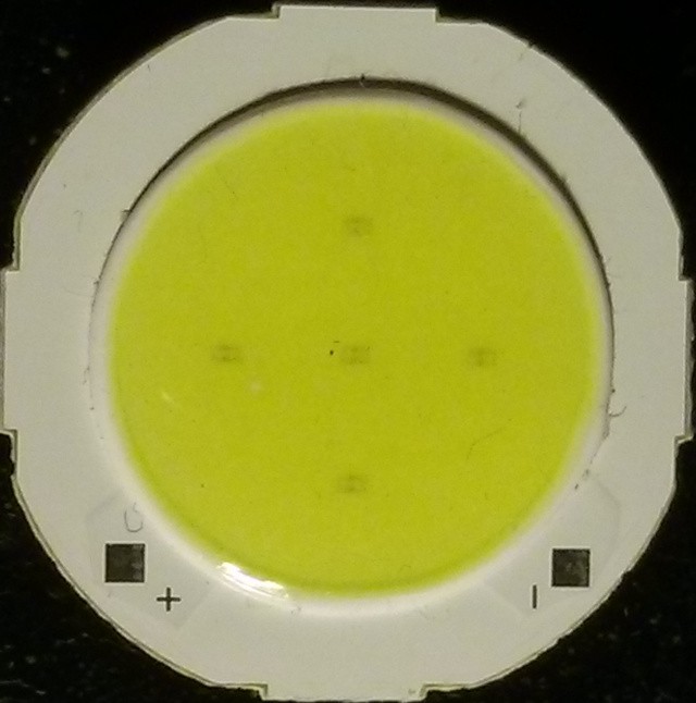
Found I was lacking proper pullups on my LED spotlight and added them. Then the final and 6th LED of my hexagonal, dollar-store flashlight board that I used for its spotlight burned out due to cascade failure due to their parallel arrangement. I bought a set of LED flashlights (about a dollar each) to replace it which contained a COB, or "Component On Board" where 5 surface-mount blue LEDs are mounted to a PCB and a layer of silicone containing a yellow phosphor converts them to white light.
![]()
I decided to add a silicon diode to drop the voltage slightly down from 5v, in conjunction with my current limiting resistor, to try to avoid potential thermal runaway in case I exceeded the power dissipation of the device on my first board.
Software Additions or Removals:
- Upgraded NodeMCU to a newer version 2.2.1-master_20190405. This fixed the KRACK vulnerability, allowed Android 6 and above to connect to SoftAP access point mode again, and allowed me to turn on the new LFS (Lua Flash Store) with 128K to save RAM. Also added the DS18B20 and I2C modules.
- Began using matplotlib, NumPy, and Scipy Python modules to improve my motor drive system (more on this below).
- Removed the Python Pexpect module, since I never really needed it.
- Converted all of the TrillSat Python 2 software to Python 3 since Python 2 was end-of-life and the Scipy module would no longer compile on my Linux distro. A lot of things broke that I had to convert:
- Switch my file() commands to open()
- Many of my literal strings were strings of bytes, so I had to specifically indicate such with b''
- The APIs of many libraries that I used only accepted byte strings or bytearrays, forcing me to convert from/to them using .decode('utf-8') and .encode('utf-8')
- There was a lone print "" that I had to convert to print("")
- I had to replace a lot of chr(x), remove some str conversions, or use 0x hex values directly (instead of encoded in strings as "\x") when they were not applicable
- An integer floor division issue with my XMPP status screen caused a large floating point value to take up the display
- Released SIMTHEO decoder version 1.2, correcting a delay bug, and modularized it so it compiles into dynamically-linked libraries for the Pi Zero ARMv6. I then had to generate two different SIMTHEO binaries for the ATtinys in their own subdirectories since my newer dynamic-linked libraries require different pre-processor defines due to the simplicity of my API.
- Successfully ported my AVR-GCC ATiny 1634 roguelike game engine for ARMv6 Pi Zero W as a finite state machine which works in combination with the dynamically-linked SIMTHEO decoder library. The game's "blind" short-text-string mode is ideal for allowing simultaneous, multi-user play over the port-based nature of packet radio with very little load on the Pi Zero W CPU. It would be trivial to change the theme from medieval to sci-fi, space, or ham-radio related.
- Removed my Virtual PTT system lieu of Dire Wolf's TXINH "inhibit input" option and added a jumper to allow this to work.
- Began working on version 1.2 of TrillSat's operating software which includes many of the changes below but has not been released yet. This includes a new, separate Python 3 module for the motor drive system.
TrillSat version 1.2 updates (not released yet):
Found and fixed 3 major bugs (compound, multivariable bugs):
- Fixed the AX.25 texting bug that prevented full, bidirectional XMPP-to-AX.25-to-AX.25-to-XMPP (smartphone-to-smartphone without any desktop computer involvement). Bug was due to 3 tricky, concurrency race conditions that were hard to isolate. Wrote script to automate simulated test environment.
- Fixed the BLDC gyro bug that was cutting out at high RPMs, more often if tilted to one side than the other. Bug was due to me nesting an interrupt function inside the wrong interrupt to bypass a hardware failure which caused gravity to affect the sensitivity of the X-axis acceleration detection differently depending on the direction of the spinning gyro and whether it was accelerating or decelerating, causing a feedback loop that triggered the accelerometer, which then interfered with the time-critical Hall-effect sensor interrupts monitoring the gyro.
- Fixed the I2C bug in my driver code which had been causing unreliable transfers for years. It turned out that I was sending an ACK back to the Pi without thinking the session was over, causing all kinds of overlapping interrupts. I also didn't perform a check to see if a Stop occurred during a read or a write, yet I was running my I2C commands as if it was a write, slowing time-critical processes. And the ATtinys were spontaneously resetting during motor use until pullups were added, confusing the problem.
Found workarounds to 3 notable bugs:
- Discovered that packet communications just three feet apart worked well in one direction but not the other, depending on which station was hosting the PBBS, exposing a timing issue. This turned out to be due to the infamous Delay between PTT assertion and audio packet - Causes dead air for seconds bug when using Dire Wolf 1.5 and my SYBA SD-CM-UAUD USB sound adapter (with the CM119 chip). Found a workaround by using ALSA's "default" plugin (in my case, "ADEVICE default:Device") instead of using the "plughw" plugin (in my case, "ADEVICE plughw:0,0"). TRILLSAT-1's SYBA SD-CM-UAUD USB sound adapter is called Device, a generic (and thus confusing) name.
- Ran into the Invalid Transmit Channel issue with kissattach where it tried to transmit on the wrong ports (8 and 2) at startup. I was able to use the "kissparms -c 1" workaround to set it into crc-type "none" right after kissattach. Apparently it's how the kernel implemented KISS.
- In my Baofeng UV-5RA radio in TRILLSAT-G, when the squelch is set to 0, the FM tuner will not activate when briefly pressing the Call button, but it works fine when squelch is set to a non-zero value--some kind of firmware bug, apparently.
Packet Radio system:
Tested live radio for the first time instead of in pseudoterminal simulations and realized that my use of multiple ports (while fine in testing) caused several issues in actual use on a single sound card, since different ports are designed for different TNCs, and there is really no reason I should use multiple TNCs unless I have multiple transceivers. So I passed my own "--mode" argument in the ax25d.conf sections at the end of the trillsat_bbs.py line to allow the software to launch in different modes depending on the callsign SSID value.
Had to create a rotating socket mechanism to increment up to 10 sockets in a ring buffer to ensure that one was always available since I could not programmatically shut down and restart the pigpiod daemon if the radio got stuck during programming in the middle of an AX.25 session since it couldn't wait for Linux to release socket 8888.
Turned off the low battery voice on both TRILLSAT-1 and TRILLSAT-G to keep it from interfering, something I first noticed when testing TRILLSAT-G over the air since it had a smaller battery.
Created an elaborate process which puts the AX.25 pipeline into a "stupor" (confusing senses, making it disagreeable, putting it into an alternate reality) to allow the single VFO, during the packet session, to temporarily switch over to the APRS frequency to send out a beacon. Since I could not break the complex chain of AX.25 communication that takes place, I made the thing sluggish and confused on purpose during the short time window when the radio changes frequencies and sends out the beacon, and then I woke it out of its stupor. I used kissparms and axctl to modify the persist, T1, T2, T3, and IDLE values, paused the PBBS, muted the mic, inhibited PTT, and programmatically told the radio to change frequencies with confirmation and failsafes in case it locked up or was on the wrong frequency.
Tested sending a text while a PBBS session was in progress on the same port from the same caller (same callsign and SSID), something that shouldn't be done since the caller would be needlessly tying up the server. This created conflicts with my implementation of the POSIX IPC message queues, which I create on the fly named after the user's callsign. So I put in checks to prohibit this connection and to limit the number of maximum users to keep the bandwidth and CPU usage on the Pi Zero to reasonable levels.
Published my first video of the radio system in operation, the first demonstration of the radio systems that anyone besides myself had ever seen. I showed all radio systems working, over-the-air packet radio communications between TRILLSAT-1 and TRILLSAT-G, including the in-session APRS beacon. Everything was on battery power with no Internet or cell towers, and I even removed the router completely. It was all at 1 watt, on 50-ohm dummy loads only a few inches apart, using the "A decoder" of Dire Wolf 1.5 as a software TNC. It was demonstrated on 145.030 MHz, and the APRS beacon was demonstrated on 144.390 MHz.
Main Motor Drive:
Decided that the motor drive system of TrillSat was too complex (too many modulations atop modulations) for me to use simple heuristics or to get the system to "drive over the hills" in the torque curve as I outlined in my earlier Three-Tridant Orbital Mechanics diagram. I needed precision much higher than my crude sensor data provided, since I was using feed-forward methods to try to predict the current needed to drive the motor when it is operating in open-loop zones in-between sensor readings, and the craft was heavy and wobbly. Decided that the dynamic forces would have to be mathematically modeled unless I added more sensors and systems (which I didn't want to do).
Began writing my first scholarly/academic paper in LaTeX on TrillSat's orbital dynamics, heavy on the equations, using algebra, geometry, trigonometry, inverse elliptic functions, equilibrium equations and vector decomposition. It was the most math that I had ever done since my college Calculus days. I wrote about 70 pages of algebra until I was able to extract TrillSat's equations of motion into about 30 core equations on two pages.
I had to teach myself the basics of astrodynamics/orbital mechanics, and lacking experience with the subject, I made a few decisions:
- Excluded momentum, since it was too complex for me to model, and I was hoping it would be negligible if I drove the motor (and planetary mass) slowly.
- Decided on Cartesian coordinates (even though I have both linear and rotational elements) and used parametric equations to bypass some of the computational problems. There are times I really need Polar, but it wasn't often enough to offset the benefits of Cartesian.
- Used "relative" spatial relations to simplify the math, so I have to perform a series of calculations to find absolute values.
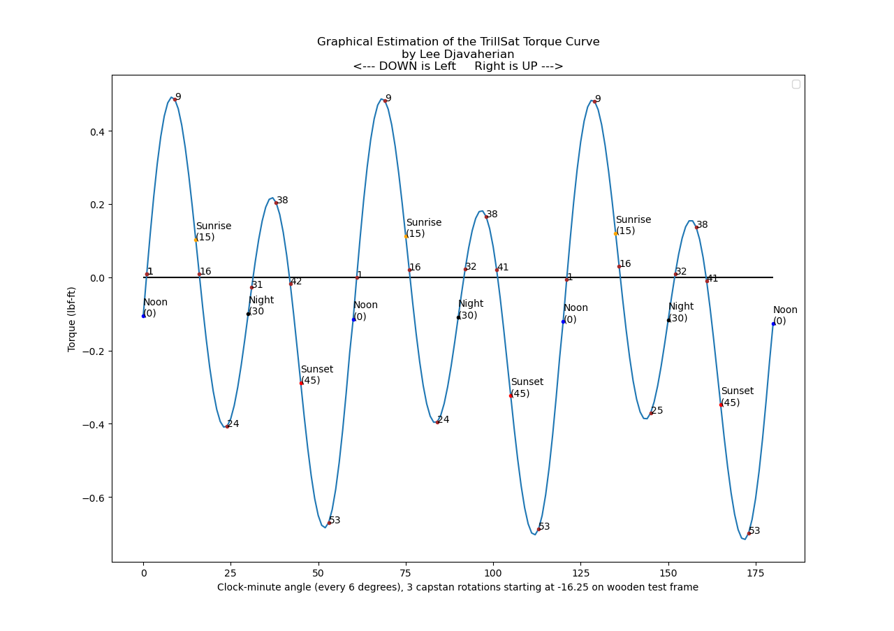
Decided to apply a computer graphing library, the matplotlib Python module and NumPy, to give me some visualizations, since TrillSat's clockwork rotations and changing angles means that many of my equations are strings of cosines, sines, tangents, arctangents, and I had a hard time visualizing whether my calculations were correct and not "out of phase".
I couldn't find a mathematical solution to find the inverse of the incomplete elliptic integrals so I applied the optimization functions of the Python SciPy Library to approximate it. In my case, it did it surprisingly quickly with high precision, but I needed about 1,000,000 complex calculations used in real-time on tiny microcontrollers, so I had to pre-generate them.
![]()
Using the new math of the torque curve (shown above), I performed my first locomotion tests on the tether at various PWM values and run times for a single 360-degree orbit, without any sensor feedback, but they were very erratic and chaotic, with the mass stalling, then whipping around causing the whole thing to swing.
Also during those tests, I accidentally touched the wrong wire feeding the batteries back into the charger which caused the ATtiny 1634 motor driver Sawyer to lock up and initiate the motor drive algorithm with long time parameters, ramping in speed very slowly while on the tether. I had to quickly untie and yank out the capstan to prevent motor damage and quickly unscrew the cover panel and short the reset line to the grounded panel. So I finally enabled emergency use functions over I2C on the ESP8266 in case the Pi locks up or goes down during motor tests, so it can shut down the motor controller ATtiny, Sawyer, when needed.
I decided that the motor modulation system, even with the torque values, was exceedingly more difficult than I anticipated and decided to focus more effort around it as the "Delta-v Motor Drive System", to maximize the precision of all elements involved so that the motor stayed inline with the idealized mathematics as much as possible to ensure accuracy. It's like a spacecraft in a Keplerian orbit--if you can provide the correct Delta-v thruster burn (an orbital maneuver) to get it into a certain orbit, physical law will take care of the rest, but tiny errors in the maneuver are grossly exaggerated, so it will be way off course until you reach a point where you can apply a correction.
The system and math are too complex to run in real-time on the ATtinys and require the full power of the Raspberry Pi's ARM processor with floating point math. Even this is too much for the ARM processor in real-time using Python 3, so I had to stage a pre-generation and then stream the torque values in real-time to the ATtiny. But the two Hall-effect switch tolerance zones were absurdly large, way too large to both correct for error or trigger data block loads of torque values, what I call "chunks", reciprocating memory buffers in the ATtiny.
What totally amazed me was that this tolerance (about 50-55 degree error for each sensor position, 15% of the total orbit, 45% for all three "sectors") is so large that the orbit can be divided into 6 sectors, "Six Sextant Orbital Mechanics", with 3 of the sectors being inside the tolerance zone themselves when the magnetic field is detected, and the edges of those 6 sectors are very precise. I was then able to create a phase lock system to auto correct the motor torques at those 6 edges, with I2C hardware flow control that triggers a chunk reload of the pre-generated streaming torque data every 180 degrees at the day/night boundaries.
In between these phase lock sensors, however, the craft is traveling by pure dead-reckoning, so I maximized the precision in my code to minimize cumulative error:
- Changed my 8-bit timer resolution to 10 bit, increase my timing resolution from .1 second resolution to .0005 seconds (.5 ms)
- The electrical current had to be moved from 7 or 8-bit to up to 10-bit (1024) phase and frequency correct values
- Any _delay statements were removed to allow modulation at small angles and higher speeds
- Passed a lot of 16-bit values over 8-bit serialized I2C, and had to brute force my own "signed-bit" since I was having trouble with the 11th bit negative values of my 10-bit torque values (the two's complement/endian arrangement gave me some trouble and I was getting fatigued)
- Scaled the floating point values properly into integers to keep the precision rather than truncate it
- Increased the shaft resolution of my math to 3600 arc to match the .1 degree resolution of the accelerometer
- Moved my timer-interrupt-based, Hall-effect sensing directly into my motor drive function to save some clock cycles
- Ensured the system switches between Sign-Magnitude (10-bit) and Locked-Antiphase (9-bit) modes automatically during the rotation
- Used the ESP8266 ADC high-impedance voltage-divider circuit (a redundancy item I added) to read series motor voltage (which affects speed and torque calculations) and also indirectly allows me to deduce the Batt 2 bank voltage after its ATtiny ADC pin failed
Created new testing methods for my motor drive system inverted on a table since the dynamic torques do not exist and the motor behaves completely differently. Had to "serialize" my angles in almost the same way Linux seconds serialize the rotational hands of a clock face for my torque streaming method that converts between motor shaft angle and positions within two, reciprocating, linear memory chunks. I ended up using integer division and modulo operations frequently and found that a good way of doing this was to rely on a starting offset that was less than a chunk in length (less than 1/2 a rotation) combined with the total number of motor torque values sent.
I could not apply effective hysteresis for the noise at the edges of the Hall-effect switches due to the peculiar interlacing of direct and indirect sensing and had to incorporate complex time and distance-based debouncing (not true mechanical switch debouncing but I treat it as such), creating speed-sensitive timing delays to change the debouncing thresholds and take into consideration the width of the 6 sextants, which conveniently differ by a 1:2:6 arclength ratio.
Created a clock-minutes and clock-seconds angular scale. The 3600-arc resolution of my motor drive system acts like seconds if they are applied to a clock and not degrees or arcseconds on a compass, which is why I prefix my angle terms with the word "clock", like "clock-minute" to differentiate from arcminute. The clock-minute angles are simply angles at every 6 degrees, like minutes on a clock face.
Created a finite and impulse burn system using that scale. Just like in a real spacecraft, there are two types of burns, or orbital maneuvers in TrillSat, a long-term "finite burn", which I call a clock-minute burn, and a short-term instantaneous or "impulse burn", which I call a clock-second burn. And the analogy holds surprisingly well, for my long-term, clock-minute burns are designed to traverse any distance, from point to point without stopping, requiring more calculations and techniques to keep it on track, whereas my clock-second burn is very simple and short, almost instantaneous, designed only for moves within 6 degrees, with no ramp, torque streaming, nor Hall-effect correction enabled.
Added an auto-calibration routine to automatically find the angles and offsets of the initial sensor placement and motor conditions for accuracy. It automatically drives the motor and reads the sensors in various ways to deduce the following:
- angles of the 6 sextant zone edges
- mechanical gear slack
- magnet holder assembly error
- static friction offset
It stores them in EEPROM with flash default fallbacks to prevent needless re-calibrations during programming and erasure.
Added some motor correction heuristics to keep the motor on track with the equations:
- sensor correction - correct known position when sensor finds it is wrong
- sensor catchup - if motor is too slow, hold last speed until it reaches new sensor checkpoint
- sensor reload - if motor reaches day/night sensor checkpoints, tell Pi okay to send next chunk
- motor boost - if sensor catchup is on, don't just hold last speed, increase speed in stages
- speed correction - if too slow or too fast, alter speed by 1/2 the error during next phase
I had to rework my ramp system to work atop the Delta-v system, instead of beneath it, to ensure time-and-distance critical maneuvers were not impacted. I was able to take advantage of the neat fact that a triangle that is twice the width of a rectangle of the same height has the same area (the electrical current and time that is used to move the motor). So I could replace that tiny "burn" with a more granular burn-of-burns, ramping up to the original value, but it would take twice as long to apply, skewing the elapsed time. This is not a problem, since I'm concerned more with distance than the arrival time. Ramp downs, however, had to be excluded 10% of the time, since it interferes with real-time correction at the 6 sensor angles (zone edges).
Created an auto-motor-move system to ease programming since the motor shaft in certain positions blocks one of the ATtiny in-circuit programming lines.
The Gyro:
After the gyro bug was fixed, I tested the BLDC gyro at 1800 RPM, 5 times faster than my original video. This puts about 2 lbf of force around the wheel, and it worked without breaking apart under its full mass. I haven't tested it on the tether at this speed yet. There is less than 1 mm clearance in some places and thermal expansion could cause the wheel to eventually scrape, but it should hopefully be enough for me to show proof of concept of a stabilizing effect in the future.
Planned updates:
Decided to 3D print and add, what I call a "camstan" in the future, but it's a larger change that I won't revisit until later since it is highly eccentric, too wide to fit into my pulley frame, and both parts will need to be redesigned, not just one. Also, the mathematics of adjusting to the error points crosses Cartesian/Polar systems, complicating the math. In the meantime, I will rely on my newer Delta-v Motor Drive System to compensate, as best as it can.
The camstan design came about after I graphed the torque curve and noticed that my 2018 truck analogy was acting like a fixed-gear system and lacked a transmission, so I combined a cam with a capstan to mimic a continuously-variable automatic transmission, or CVT. A capstan can be shaped like a cam since the tether acts somewhat like a cam follower. It turns out that since there are only two sinusoidal cycles per rotation, a simple, dual-lobed, camstan could work, but there is some cleavage error where the tether spans across and cannot act on its surface (example below, the cleavage dramatically smoothed out without any tapering):
![]()
I designed a model of the camstan by having my Python 3 torque-generation function output a series of torque displacements (radii) for each of the 3600 angles per one rotation, and using the Cartesian-to-polar relationship was then able to convert them to [r cos theta, r sin theta] x,y pairs which could then be read by OpenSCAD's Cartesian-only polygon function to generate the unique off-axis, dual-lobe shape, which I then extruded into 3 dimensions.
But rendering the actual shape for 3D printing, with the tapering (not shown above) was difficult, and I had to stack a series of slices of the entire polygon at various exterior offsets (kind of like scaling them) to match the algebraic, Cartesian function of a half-circle, like cutting a shape into the fore-edge of a book.
Decided to add a new sensor and plan to 3D print a minor change in the future to allow it to be incorporated. I was almost correct in my assumption that I had the bare minimum sensors needed for accurate motion, but I needed one more, which I'll explain in the paper I'm writing on TrillSat's orbital mechanics.
Decided that when I build the LoRa space pod, I will add a keyboard and display to create a secondary LoRa client for craft control (since I will need another LoRa board to communicate with it anyway).
Explored creating a virtual astronaut simulation inside the CPU on the space pod which I call an AAR virtual pet (an Alternate, Augmented Reality) since it interacts with its own alternate reality in combination with real world sensors, but without visual data (sensor data only). The astronaut could have some autonomy, "leave" the pod and enter the main craft affecting some of its functions (as if an astronaut was walking around flipping switches and performing manual overrides) and distant callers could get status updates on what the astronaut is doing.
Explored creating the 2-meter antenna as a pendulum attached to the top of the craft to act as tuned mass damper, raise its height, raise the center of gravity of the craft, keep vertical polarization, and act as crude X-axis accelerometer for additional redundancy. Curiously, the length of the antenna is fixed to match a certain RF frequency, and it would serve dual-purpose, also match a physical pendulum frequency.
-
Requiem for a Space Elevator
09/07/2018 at 10:52 • 0 commentsThe Japan Aerospace Exploration Agency (JAXA) is said to launch a tiny space elevator next week.
Just like TRILLSAT-1, it isn't a "real" space elevator, as this is still the domain of science fiction, but it serves as a miniature test platform. But the Japanese spacecraft is said to be the first experiment of a tethered "elevator movement" in actual space, which is pretty cool.
My TrillSat project will no longer be updated on this Hackaday.io project page, and any future updates will resume on its main site at http://greatfractal.com/TrillSat.html. I plan to take a long break before I resume, as this competition sucked most of the fun out of it for me.
TrillSat's latest subsystem #Tethered Haptics Using Morse Pulses was a project page I specifically created for the Human-Computer Interface Challenge (since the judges ignored TrillSat completely in the first 3 challenges), so this actually marks the 4th loss for TrillSat in a row.
As evident from my log entry back in July, the 2018 Hackaday Prize competition has been one of the most disappointing experiences in my life, something I will never repeat, as I rarely extend myself or personal projects in this way. I was overjoyed back in March 2018 when the competition was first announced to find out that TrillSat qualified for 4 of the 5 challenges and felt like the luckiest person in the competition. It is inconceivable to me that all 80 of the winning projects so far could have beaten TrillSat on merit--and this prevented it from even entering the finals.
The only reason that I decided to put in the final effort for the 4th challenge was mainly a matter of principle--it served to complete what I originally set out to do back in March. Suffice it to say, while TrillSat is an open-hardware, power-harvesting, robotic platform with numerous human-computer interfaces and thus directly qualified for 4 of the 5 challenges, it is definitely not a musical instrument and won't be entered into the 5th challenge. The judges can relax and don't have to look at it any longer.
Again, thanks followers/likers for recognizing this project--it was the only beacon of light in a dark place.
TRILLSAT-1, signing off.
-
Centripetal Force and the BLDC Gyrofan
08/28/2018 at 01:00 • 0 commentsI started to look more closely at the centripetal force equation, since I've been wary of raising the Gyrofan speed higher with its full mass, as I didn't know exactly how much force was being generated. I'd like to ramp the thing up to get appreciable inertial stabilization, since my first test of the Gyrofan on the tether a few days ago had little effect at 360 RPM. The equation, though, shows that I was way too conservative and underestimated the non-linear effect of RPM on centripetal acceleration.
I also forgot that the high pitch of the sound isn't generated by the frequency of rotation but by the frequency of the electrical steps/pulse generation, which is much higher on a BLDC.
As the gyro speed increases (which increases gyroscopic stabilization), centripetal acceleration increases
exponentially(author correction 1/31/2021: the equation ac=v2/r increases quadratically with respect to velocity, not exponentially, a mistake I should have realized from my fractals and scaling class). And since centripetal force (and the related centrifugal force) is mass x acceleration, the force increasesexponentially(quadratically), too. If you double the RPM, for example, the force doesn't double, it squares. Doh!The 24 steel spheres and their PETG sockets are somewhere around 5 grams each, plus or minus a few grams (heck, I forgot to even weigh them before I closed up the case!). At 360 RPM with a radius of around 5 cm, this creates a force of only around .08 lbf (.36 N).
But at 3 times that RPM (1080 RPM), the force would go up to around .72 lbf (3.2 N), 9 times the force, since 3 squared is 9.
And at 50 times that RPM (18,000 RPM), the force would go up to around 200 lbf (888 N), 2500 times the force, since 50 squared is 2500.
So this presents an interesting situation, since the actual stabilization effect is related to angular momentum, and is not
exponential(quadratic). In other words, I have to spin it fast to get the stabilization to occur, yet the unwanted force on my wheel starts to go upexponentially(quadratically)...I am still down in the low numbers, though, and so I tried sending a gyro 33 command to ramp it up to 1320 RPM, which applied approximately 1 lbf of force (4.8 N) around the wheel. It runs for a few seconds, but then cuts off before I can evaluate it. For some reason, my stall detection code is randomly activating and is shutting down the BLDC. What is weird is that this bug occurs less often when the craft is tilted to the starboard side, and more often when tilted to the port side, but I've ruled out the accelerometer. And I don't think this is related to gyroscopic precession, either, since it also occurs at really low RPMs. Very odd. So I have to review all of my gyro code (and maybe even open up the case to check for loose connections) before I can resume testing.
My BLDC code is a nightmare, by the way, mainly due to the fact that I couldn't use the 8-bit hardware timer to drive the pins directly. I'm using them for other things, and even so, I need 3 pins for the 3-phase motor, but there are only 2. I use the pin change interrupts to detect the 3 hall-effect sensors, but for PWM, I used the 8-bit overflow and CTC interrupts to chop the power to the coils, using software routines to changes the pin states. And all kinds of bad things can happen: the pin states can change while I'm trying to read their states, counter overflows can occur, the timer interrupts can occur outside of my functions before I get a chance to read them, my code might not complete before the next interrupt, etc. There are still a lot of bugs that I need to work out.
The new ATtiny 1616 that came out last year would solve some of my problems, but I just need to improve my ATtiny 1634 code and find creative ways to handle it. I've got the main drive motor and haptic morse detection running on the 16-bit timer, and I use the 8-bit timer for the gyro and miscellaneous functions.
When the BLDC runs at higher RPMs, every clock cycle counts, but unfortunately I do a lot of things inside my interrupts which eat up a lot of the available cycles. For example, with 36 interrupts per mechanical revolution, at 3600 RPM, for instance, one revolution is 1/60th of a second or .016 seconds. The CPU clockspeed that I use is 8 Mhz, so it only has 133 or so Khz for that revolution. Split that into 36 parts, and I'm left with around 3700 cycles, used by the C compiler, per interrupt.
One way I've dealt with this is to create 3 different Gyro modes that activate automatically depending on the RPM assigned, called BLDC_LOCK_MODE (0-1320 RPM), BLDC_PWM_MODE (1360-1480 RPM), and BLDC_FAST_MODE (1520 to all out). But even in the "all out" mode, it tops out at a fairly low RPM due to my code efficiency. So I need to add a "step-skipping" mode as well.
Once I fix this primary bug, though, I'll retest at higher RPMs and document the results.
-
Updated TrillSat and SimtheoDecoder to Version 1.1
08/25/2018 at 03:28 • 0 commentsOk, I made the first update to the TrillSat source code since it was published almost 3 months ago, primarily to add the new #Tethered Haptics Using Morse Pulses subsystem, and added it to the Files section. The trillsat.c source is now dependent on (and performs a C include of) simtheo.h, my external Morse decoder module, and is now also dependent on eeprom.h (from the avr-libc project) for the haptic passcode storage. The trillsat.c source also adds the appropriate defines, global variables, pin/interrupt/timer initialization; adds two ISR interrupt routines for Sawyer and Huckleberry, adds a new function called Process_Haptic_Command to perform the actual command processing, adds the EEPROM haptic lock routine, and it, along with trillsat_bot.py, adds the new XMPP and THUMP commands.
They also temporarily disable the haptic system and reset the correct 16-bit timer prescaler during motor operations, but they do not yet tell Huckleberry to turn on the LED (in case it was grounding the MISO line which prevents hall-effect feedback during a non-haptic motor operation). For now, I just control this manually using a new hucklight [1|0] command during testing. And the BASH programming scripts for the two ATtinys for in-circuit programming were updated to compensate for the new haptic system running over the same line.
The simtheo.h C module is statically linked, compiled at the same time as trillsat.c. In the future, I plan to clean up the module to allow it to be dynamically linked, but for now, I just wanted to make sure that all of the code was published to show how the THUMP system was implemented for a capstan cablebot. I also updated simtheo.h to remove a small delay that was causing problems and to correct a typo in the README file.
The THUMP system can, of course, be implemented differently in different situations, depending on the type of craft or function it performs, but this is how I implemented it for TRILLSAT-1.
-
Four New TrillSat Videos
08/24/2018 at 01:31 • 0 commentsI spent the last three days making 4 new videos for TrillSat:
- Introduction
- XMPP Command System
- Tethered Haptic Morse Code System
- Inertial Gyrofan
I still need to make 3 more videos (the power regulation, motor drive, and packet radio systems), but these are more complicated for me to demonstrate, so I'll work on those videos at a later time. But I hope they now give you a better feel for the device, such as the scale of the craft, how it swings, and how the command systems work. It's buggy and rough, but it's a real thing.
I decided to go ahead and create a YouTube channel called TrillSat just for this project and moved my old motor control test video to the new channel. Anyway, here they are:
-
Complex Orchestration of Systems
08/21/2018 at 05:33 • 0 commentsOver at my new #Tethered Haptics Using Morse Pulses project, I have decided to leave the haptic system enabled full time on the TRILLSAT-1 prototype, instead of just during low-power situations, and have created a new EEPROM haptic passcode validation system which reduces the chances of nature (or a casual passerby) to spontaneously enter commands over the tether. A two-capital-letter passcode is set via XMPP which allows 676 combinations.
While simple to use in a "typical" system, implementing all of this on TRILLSAT-1 is more complex due to both its oblique angle (and another angle which changes depending on the sun), and the fact that it resource-shares a single overloaded MISO line using two ATtinys running in parallel. I'm essentially cramming a new, full-time system onto an already overloaded line, and all of these systems have to be carefully orchestrated. There are some interesting nuances in exactly how the circuits and software need to interact to allow successful operation.
The MISO Line
The SPI Master In Slave Out line is now used for five different purposes:
- Occasional bitbang SPI in-circuit programming of the two ATtiny microcontrollers
- On/Off control, by both the Pi and ESP8266, of the LED spotlight
- Motor position alignment via a hall-effect switch read by Sawyer (the motor-control ATtiny)
- Serial bus between Sawyer and Huckleberry (the power-regulation ATtiny) for repeating standard Morse code characters from haptic input
- On/Off control of the LED spotlight by Huckleberry
And the settings vary depending on whether or not the Pi and ESP are up or down, the LEDs are on or off, the position of the motor is aligned over one particular hall-effect switch, and whether any in-circuit programming or haptic communication is taking place.
The I2C Lines
Two I2C lines (which are also used as SPI lines) are shared by two masters (Pi Zero W and ESP8266) and three slaves (LIS3DH and two ATtiny 1634 microcontrollers), but the infamous hardware I2C clock-stretching bug on the Pi has caused many difficulties over the last two years, forcing me to both slow down the bus and spawn off jobs in parallel so to not delay the line.
These lines are the only way to access the LIS3DH registers, so if the Pi or ESP go down, the LIS3DH can only generate interrupts to one of the ATtinys based on previous settings and the registers can no longer be set dynamically. So I had to make sure the Pi (or ESP) sets it correctly before any power failure occurs. Because the three slave devices cannot communicate with each other, the only options for the ATtinys would be to set variables which are polled by the Pi or ESP, if active, so they can then send master I2C commands as needed.
The LED Spotlight
The LED serves as both a spotlight for illumination and also an important diagnostic tool, allowing Morse code output to be visualized without turning on the haptic motor, and it can even flicker when performing SPI programming without affecting the data integrity.
If all systems are operational, the ESP should keep the LED spotlight ON (floating), but the Pi should keep the LED spotlight OFF. Because the LED is being controlled at the transistor base after the series resistor, it doesn't ground the entire MISO line and leaves it usable. So the Pi and ESP can keep the LED off, yet still allow the MISO line to operate for SPI programming, haptic Morse signals, and hall-effect motor position detection. But if Huckleberry needs to control that LED for testing when pulsemode is 0 (visual only; no haptic), the Pi and ESP must relinquish their hold on the LED spotlight, and then Huckleberry can control it. Sawyer can control it too, but it never needs to. It just needs to monitor that line at all times for its hall-effect switch, in-circuit programming, and incoming haptic signals.
So if Huckleberry is sending Morse to Sawyer, you'll see the LED spotlight flash, unless the Pi and ESP have turned it off. But if the Pi is down, it is no longer grounding that transistor base and the LED spotlight comes back on. And any haptic transmission from Sawyer to Huckleberry will light up the LED if the Pi and ESP are down.
Now, if just the Pi is down, the ESP should know this, as it controls the power to the Pi and has full communication with it over the UART. So the ESP can always take over to keep the LED spotlight off, too. It should default to ON, so haptic pulsemode 0 will work by default.
But if the ESP is also down, haptic pulses to Sawyer must always light up the LED.
Unless... the motor is in a position where a particular hall-effect switch has triggered, then the LED will remain off and neither Huckleberry, nor the Pi or ESP, can turn it back on. But in this case, haptic communication is no longer possible with Sawyer.
I've decided that I need to arrange the jumpers on the two hall-effect switches to make the one that uses the MISO line on the West, sunset-facing side. I'll explain why below.
The Sunset Position Hall-Effect Switch
When the Pi wants to move the motor, it must turn off the LED spotlight (to keep the light from flashing at night), then instruct Huckleberry to turn on the LED spotlight (but it doesn't really come on, due to the Pi override) to release the ground on the MISO line to free up the sunset hall-effect switch needed by the motor for position sensing, then tell both Huckleberry and Sawyer to ignore haptic pulses by disabling the interrupt, then tell Sawyer to move the motor, then it tells Huckleberry and Sawyer to receive haptic pulses again, then tells Huckleberry to set itself back to where it was, and then the Pi turns the LED spotlight back on again, to give Huckleberry a chance to control the light if it needs to.
If the LED was on, it will turn off if the motor is moved to the sunset position. And when that hall-effect switch is triggered, Sawyer can no longer be programmed nor receive haptic Morse code messages either.
Huckleberry could set a flag which is polled by the Pi and ESP8266 to instruct Sawyer to drive the motor away from the hall-effect switch to allow it to temporarily see those signals, but if the Pi and ESP are offline, this is not possible. However, if the hall-effect switch that uses the MISO line is the one at the sunset position, the most precarious physical position, where the planetary mass only needs a slight nudge to physically fall away from that sensor into the Night "tridant", it allows the user to simply "shake" the tether to free the sensor.
When programming Sawyer using a BASH shell, I added updates to my trillsat_burnsaw.sh script to first check to see if the MISO line is sinking (which means that either Huckleberry is grounding the line to keep the LED spotlight off or the sunset hall-effect switch is sinking), and then use i2ctransfer (one of the commands from the Linux i2c-tools package) to send an I2C command to Huckleberry to turn on the LED spotlight, and then checks again. If the MISO line is still sinking, it informs the user that the motor position must be moved before programming can commence.
When the hall-effect switch is not sinking, 5v is sent through 1502 ohm resistors which meet up with a 1k resistor to form a 1.5k/1k voltage divider at the LED spotlight's control transistor, sending about 2 volts to the Pi and MISO line which doesn't interfere with the Pi's 3.3v logic bitbang SPI programming. When the sensor is sinking, Sawyer sees a direct ground at the MISO line, but Huckleberry now sees the 3.3v line after only a 334 ohms (502 ohms + 1k in parallel) load is applied, which draws only about 10 mA on the Pi GPIO pin, not enough to keep the SPI programming from working, and the 3.3v logic is still seen as a 5v logic high on Huckleberry. It's interesting that if Huckleberry grounds the MISO line, then this does block Sawyer from programming, even if the hall-effect switch is not activated, since Sawyer sees a 1k/502 ohm voltage divider, which lowers it to 1.1 volts, too low for a 5v logic high.
And when programming Huckleberry, I also added updates to my trillsat_burnhuck.sh script to send an I2C command to Sawyer to tell it to disable its THUMP interrupt until programming is complete. This is necessary to ensure that, if the sunset hall-effect sensor is not blinding Sawyer from the MISO line that Sawyer doesn't try to interpret Huckleberry's SPI programming signals as haptic Morse code instead.
Whew! I told you TRILLSAT-1 was more complicated than a typical use case. But, wait, there is more!
Tilt Angle Changes THUMP Parameters
And finally, because TrillSat is an oblique-angled craft that changes its tilt angle for solar tracking, the tilt increases X-axis (or even Y-Axis) acceleration due to gravity that must be subtracted by the accelerometer to keep the sensitivity constant, instead of inversly proportional to the tilt angle. But the physical constraints of the tilt also limit the sensitivity, so both the LIS3DH high-pass filter REFERENCE and the threshold CLICK_THS registers would probably need to be read/set after ever motor move.
Ideally, I need two axes (X and Z) in TrillSat for consistent, single-axis click detection at every tilt angle, where a typical, flat, vertical hoistbot, that didn't tilt, would need only one. The accelerometer can be configured to detect multiple axes (6D orientation), but it would still have to be configured for each tilt angle to know how to interpret the pulse for an interrupt, which brings me back to the same problem. I do like this feature and may use it in the future, as it can exclude pulses in the wrong direction. Without using the LIS3DH I2C line, which is not possible on the ATtiny 1634s in my situation, or the Autoreset mode (which I'm still experimenting with), the accelerometer system is not smart enough for dynamic calculations. So I have to rely on the Raspberry Pi Zero W (or ESP8266) to set the accelerometer over I2C beforehand, which would allow the THUMP system to operate normally using interrupts at that tilt angle, until it changes again.
But because Sawyer and Huckleberry will continue to track the sun, even if the Pi and ESP are offline, this is not an ideal solution. So before a "planned" low-power shutdown situation occurs, I'm going to either have to switch to the Autoreset mode or have the Pi turn off the high-pass filter and thus make the pragmatic, but sometimes incorrect, assumption that the system is always level. This would mean that the haptic passcode could be easily unlocked at noon, when solar power is at maximum, or at night when a "shake" can move the mass to solar midnight position and also level the craft. Then, when unlocked, any, non-haptic, motor locomotion operations will be told to stop at noon position, to ensure subsequent haptic commands are easy to enter, until the THUMP system times out and normal solar tracking resumes.
And there are many more orchestrated systems like this in TrillSat--this is only a small example.
So just because things seem fairly easy going over at my #Tethered Haptics Using Morse Pulses project, every new system I cram into the TRILLSAT-1 prototype is a logistical nightmare. But this is by design--I wouldn't have it any other way. It is exciting!
That's the main reason I build projects like this--to see what the maze-like constraints of Nature and Information allow me to do, how much I can overload, how much I can't, to find those outer boundaries, and then, go deeper and find those inner ones, too.
-
Haptic Morse Code System is Working
08/16/2018 at 09:04 • 0 commentsThe Tethered Haptics Using Morse Pulses (THUMP) subsystem is now working on the TRILLSAT-1 prototype which allows two-way haptic communication using the A-Z subset of International Morse Code. It operates in parallel on both ATtiny CPUs, and creates its own serial bus protocol for daisy-chained, asynchronous operation. I've published a separate project page for it called #Tethered Haptics Using Morse Pulses and entered that project into the 2018 Human Computer Interface Challenge. I also released my SIMTHEO Decoder module source code under LGPL 3.0. It can be useful for a variety of different types of tethered robots, such as hoistbots and winchbots (and oblique, capstan cablebots, like TrillSat). I will release the updates to the TrillSat source code when I get a chance, which will show exactly how the THUMP subsystem is applied to the TRILLSAT-1 prototype.
-
Hope, Revisited
08/10/2018 at 02:14 • 0 commentsSix days ago, one of my 1980's school classmates was announced by NASA to be one of the first two US astronauts to fly on a commercial SpaceX Falcon 9 rocket, scheduled for next April, finally returning the US to human spaceflight after the shuttle program ended.
In the NASA photo, he is 3rd from the left, giving a big smile and thumbs up like All Might (for any My Hero Academia fans out there...)
I had mentioned him months ago in the Introduction section of this project, since his achievements over the years were one of my motivations for actually building TrillSat as a self-contained satellite/spacecraft analog and not just a traditional radio station (and like many astronauts, he even has a ham radio callsign--how cool).
Thanks, Bob, for setting the bar extremely high (literally) and reminding me that it is still worthwhile to do things "not because they are easy, but because they are hard".
The TrillSat project on Hackaday has been reactivated and work has resumed. More details to follow.
-
Build hope?
07/25/2018 at 02:43 • 3 commentsThe twenty 2018 Hackaday Prize Power Harvesting Challenge winners were announced today, and again I did not win a single thing, not even a non-monetary achievement. This is the 3rd loss for TrillSat in a row, and I see a trend here, unfortunately.
You'd think that its unique mass-tilt/catenary spiral-axis solar tracker (both elevating the craft for line-of-sight radio communication and approaching dual-axis efficiency) using a single $9 screwdriver motor (with a custom H-Bridge built into the handle) would win at least something, right? If so, you would be wrong.
You'd think that the only tether/winchbot in this year's Hackaday Prize competition might have a chance to win something. Heck, at the time of this writing, tether or winchbots are relatively rare, and TrillSat uses an onboard capstan winch for aerial locomotion, which is very rare (I've never even seen one used in this way before) and uses complex PWM drive mechanics. And it even has a gyrofan, using mass x velocity for experimental inertial stabilization built out of a repurposed DVD spindle motor, and the BLDC is driven via programming of a single ATtiny. But alas, it didn't win the robotics round--not even a non-monetary achievement. The capstan was kicked to the curb.
You'd think that a tiny audio/data/PTT interface custom-built to connect to a $26 ham radio (which was dismantled to eliminate weight and allow variable power from both series cells and boost converters) with a custom program that uses 16-byte chunks to quickly program the clone-mode flash to allow it to mimic the features of more expensive dual VFO's for both APRS/Packet functions during a single session would at least win something, even a non-monetary achievement, right? Sorry to disappoint you again.
You'd think that a custom Packet BBS in Python on a Pi Zero using Unix standard streams instead of the C library, connected to a custom XMPP server in Lua/NodeMCU on an ESP8266, things that had never been programmed on those architectures before (to the best of my knowledge) would at least earn the smallest of awards--again, nope. I even had to build a software simulation in order to test it, since I couldn't put it on the air. Heck, I even added waterproof, inductive Qi charging... Cool, right? The judges don't seem to think so.
And you'd think that showing proficiency with 4 interconnecting CPUs and 4 languages ATtinys (in C), ESP8266 (in Lua), Pi Zero (in Python/BASH) on a single project might garner some cred from the judges, right? Nah! It doesn't appear they look at such trivial things...
Oh, and the care taken to design all parts in OpenSCAD so the majority of the unit could be printed on a Prusa i3 printbed in PETG (built from kit, no less), using pronsole on a Raspberry Pi 3 would garner at least a tiny bit of modern maker cred, right? That would be a big NO.
Oh yeah, and the wooden Ark and Test Frame support structure that I had to build to test and calibrate the unit indoors--it's another project in itself: it folds, uses counterbalanced tethers, collapses for storage, and assembles and operates in several different modes. Neat, right? Ha! No prize for you!
And finally, I built an actual weatherproof, temperature-controlled prototype (it's not just vaporware like some of the projects), strong enough for testing, and I published all of the source code, schematic, and video. I also documented it in great detail (almost 200 pages), including an itemized Bill of Materials. But I also went through the trouble of writing up separate project text for Hackaday (until I ran out of room). Did I get recognized for such meticulous work? Of course not.
I don't see this trend changing and have therefore decided not to enter my haptic, tethered Morse code system into the 4th challenge (Human-Computer Interface). The competition is over for me. All future updates to the TrillSat project will take place where it first began at http://greatfractal.com/TrillSat.html.
Thank you Hackaday followers/likers for taking the time to acknowledge this project. I often work on my projects in a social vacuum, and your simple gesture means a lot.
-
First Video of Motor Testing
07/16/2018 at 06:14 • 0 comments
I just published the first video of the two motors in operation, showing the tilting of the solar panel/capstan hoist mechanism on the tether using the wooden Ark and Test Frame and also showing the Gyrofan used for inertial stabilization. It's the first YouTube video that I've ever uploaded, and it's pretty crude. I was able to fully load the mass on the gyro wheel and ramped it up to a fixed RPM, which it holds fairly constant, based on hall-effect sensor feedback. The wagon-wheel effect is pretty mesmerizing.I also made a pass at computing the solar position using just the two CdS LDRs at rest, instead of relying on sunrise/sunset tables, but the trigonometry is surprisingly tricky. It's easy to find the brightest part in the sky--you just move the craft until the two opposing LDR sensors are close in value to one another, but it's much more difficult to estimate solar position using just these values alone. In other words, to have the craft "see" the sun and report its exact position is difficult.
First you have to know the angle of the craft (which I already know via the accelerometer), and then you have account for Lambert's cosine law, which is fairly easy. But if the angle of the craft is not horizontal (or even stationary), you don't really know which side of the sun to which one of your LDRs might be pointing. I can use sunrise/sunset tables for my location, but this requires an accurate clock, which is also a problem (as the lack of RTCs means that I have to manually set my clocks, and auto-setting them from solar position isn't accurate to more than around 30 minutes, which brings me back to the same problem...). So rather than estimating "where" the sun is, for now I'm going to have to just go out and find it like traditional solar trackers do, by moving the motors to find the brightest point.
I'm encountering some additional problems, too: the paracord sheath tends to slip over time, allowing the internal fibers to bunch-up, making the mechanism less smooth as I test. Testing it on the rough PETG snags and takes a toll on the fibers. And the Sign-Magnitude/Lock-Antiphase orbital mechanics that work so well testing on a table, which I added to my Park command, need to be heavily tweaked for the forces on the tether.
The capstan/motor is powerful enough to drive and tilt the craft, but the PWM slow-starting torque is low, and raising the torque to overcome the static friction causes jerks. These jerks were fairly low in early testing on the tether, but when I attached the heavy Planetary Mass, the jerking is heavily exaggerated. So I'll have to pulse the motor at higher current to overcome the static friction, then quickly slow it down. I might also experiment with PFM modulation in the future.
If you notice, in the video, you can hear the high-pitched whine of the PWM (since I use audible frequencies), but I have to raise the duty cycle fairly high before it starts moving (unless it is on a "downhill", and then it whips around really fast and has to be slowed down (which adds wear to the paracord). The ball-damper that I added inside Planetary Mass helps to remove the stress of the jerks, though.
The orbital mechanics aren't going to be a graceful truck driving down a smooth, sinusoidal hill, as I illustrated in my diagram--that's just the idealized path. In reality, it's going to be like a old truck driving down a bumpy, rock-strewn road full of potholes. The driver will have to hit the gas hard at points, then let off and hit the brakes, etc.
TrillSat
Texting Without Cell Towers, Power Grid, or the Internet: IoT meets AX.25 Aboard an Arboreal Space Elevator