 DTeel
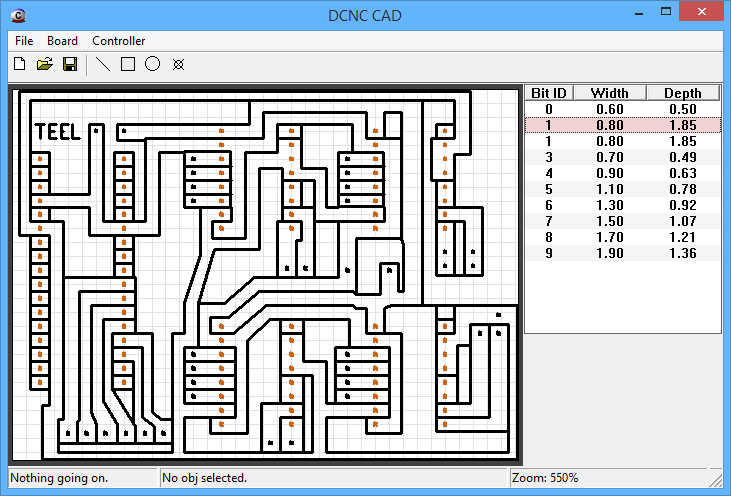
DTeelSo I spent yesterday evening drawing up the schematic for the controller, and then designing a board in my CAD software so I can route out a board on the machine that the board will be used in. Because I'm currently using a breadboard.
Heres the design I came up with, not real fancy considering the basicness of my CAD program, but it should work just fine. Dont judge the mess, it took about 1.5 hours to throw together. Mass object selection (so I can move/delete groups of objects) would be a really nice feature for me to add in.
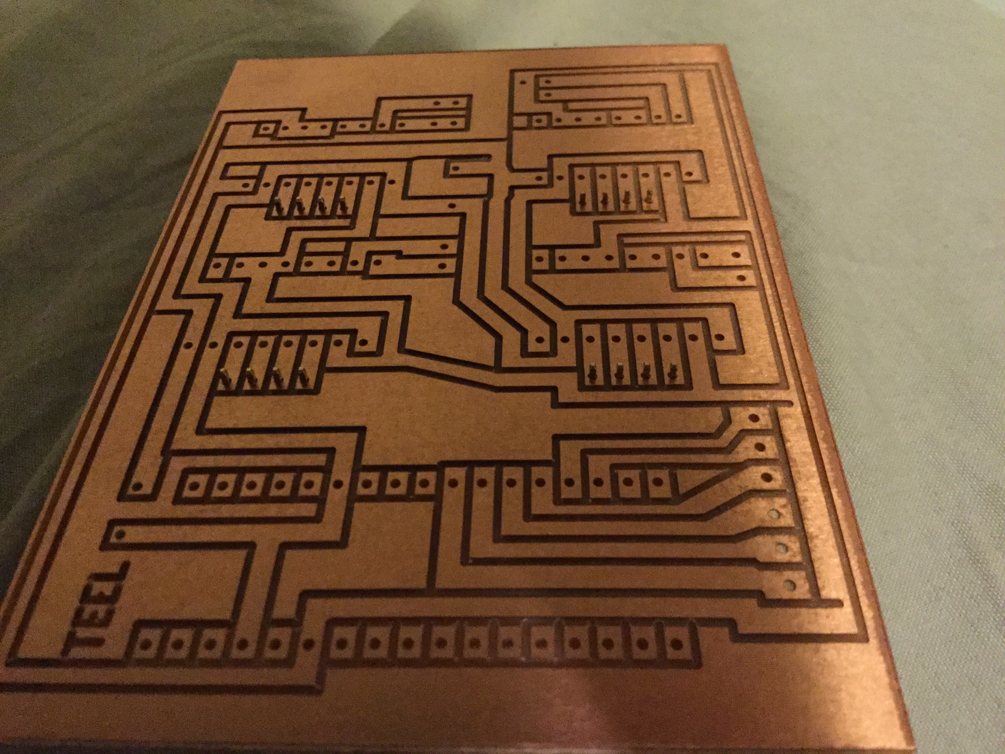
So then I etched it to a board. And this is what I got
I had a few female headers around, and all the male headers I need and the capacitor, so I went ahead and soldered them, but I'm still waiting on more female headers to come in the mail before I can fully assemble it.
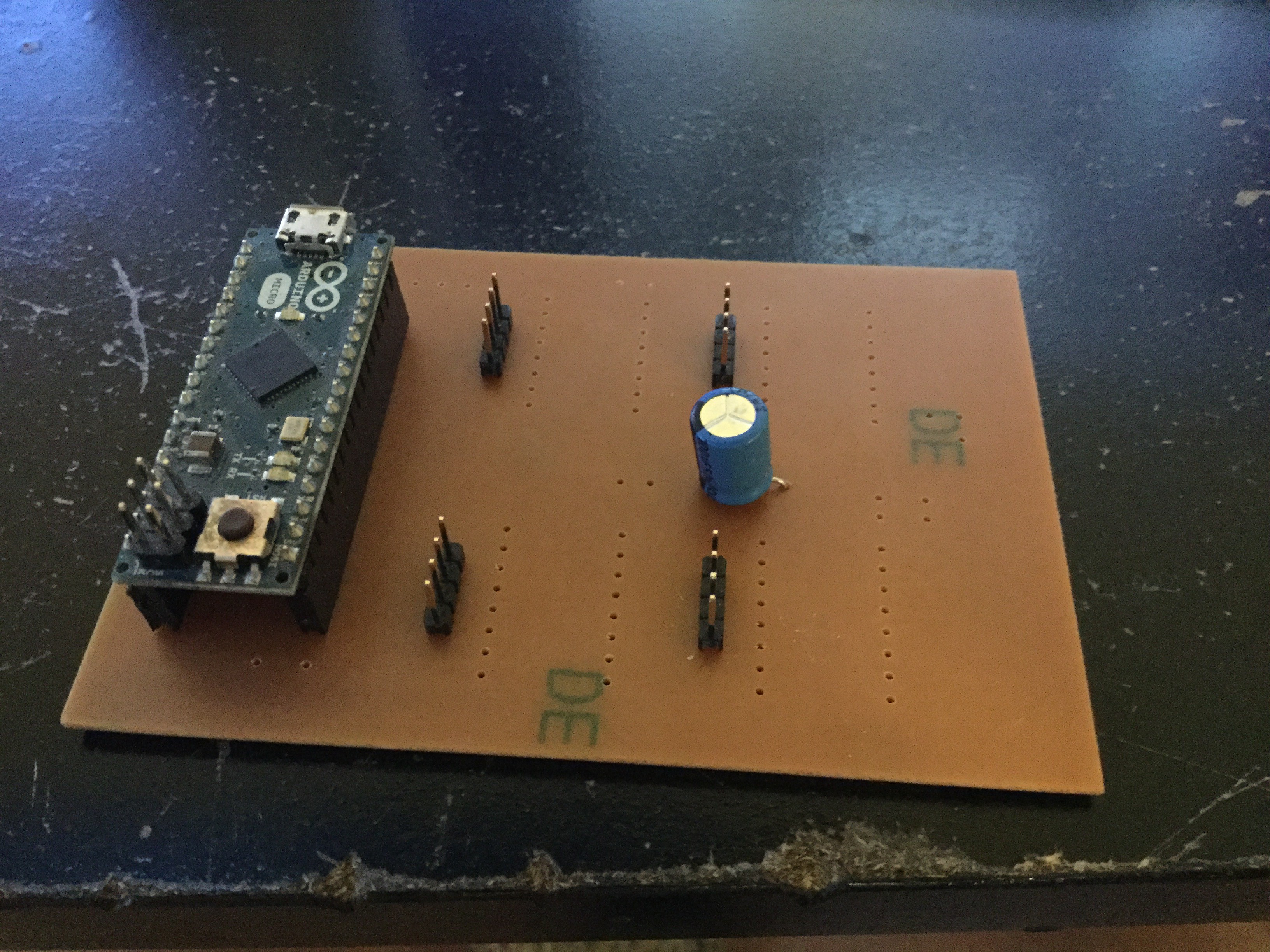
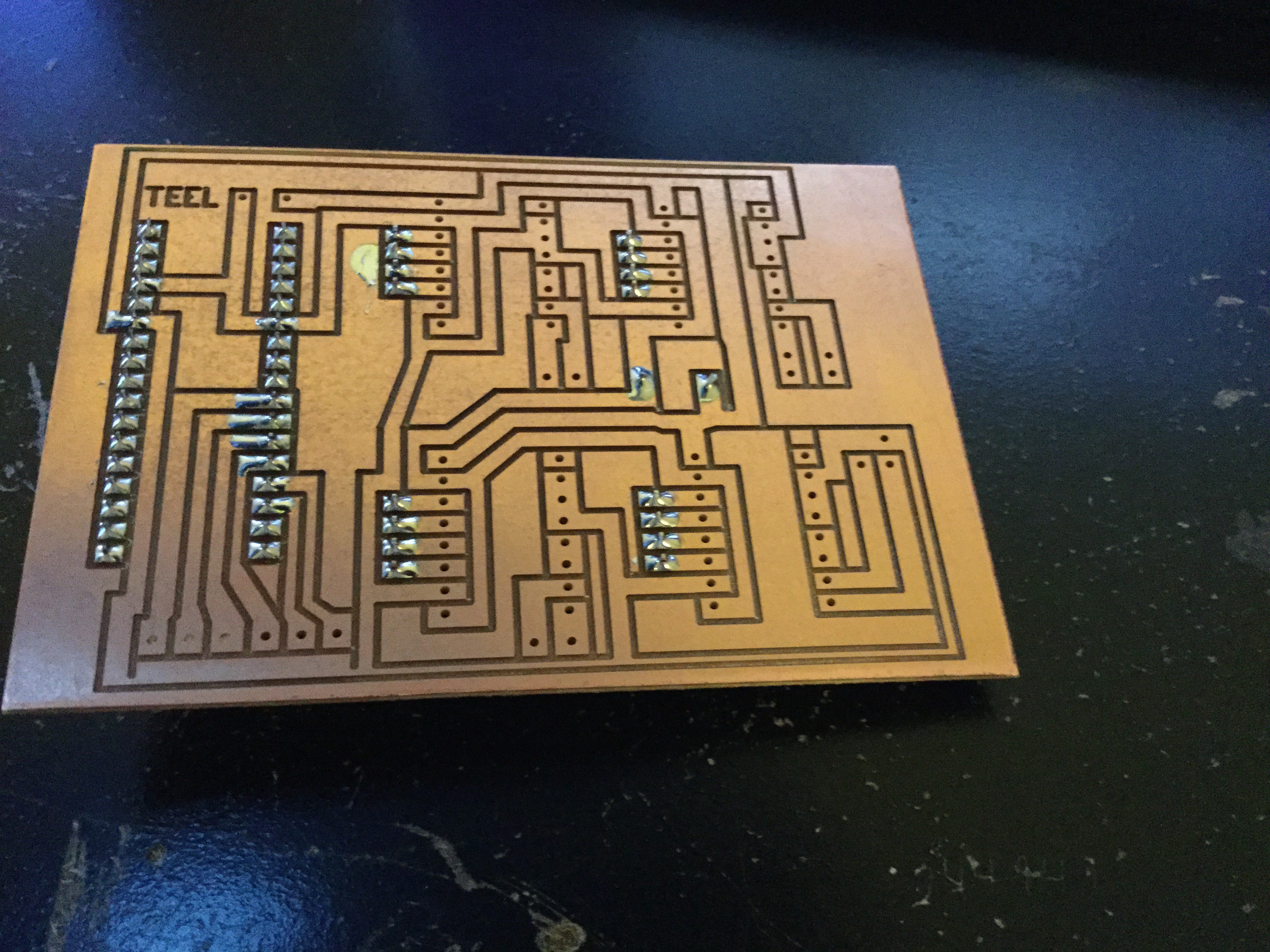
I found I like soldering on routed PCB's as its much harder to bridge traces. And I also found that I cant find any cheap off brand arduino micros, so I'm going to use my arduino micro in this project and just buy a $7 off brand one to replace in my inventory. At first I wasnt going to use an arduino in the final version, but then I realized why not? It provides an easy to use and setup computer interface and I can redesign the board to fit a $7 version (well, not an exact one, but it would work) if I ever make more. So fuck it.
Now I just wait on a package in the mail so I can fully assemble it and replace the breadboard.
In the mean time I'll design a housing and print it out to keep dust out of it, and so I can mount a small fan to keep the stepper drivers cool.
Discussions
Become a Hackaday.io Member
Create an account to leave a comment. Already have an account? Log In.