 DTeel
DTeelSo I felt that a keypad to control the motors installed on the fixture itself would greatly ease zeroing this bad boy in when I'm going to mill a board.
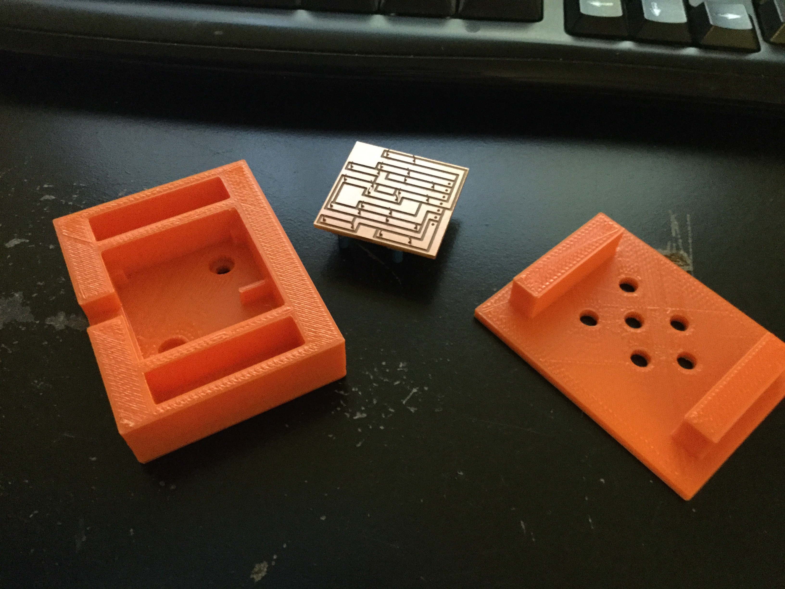
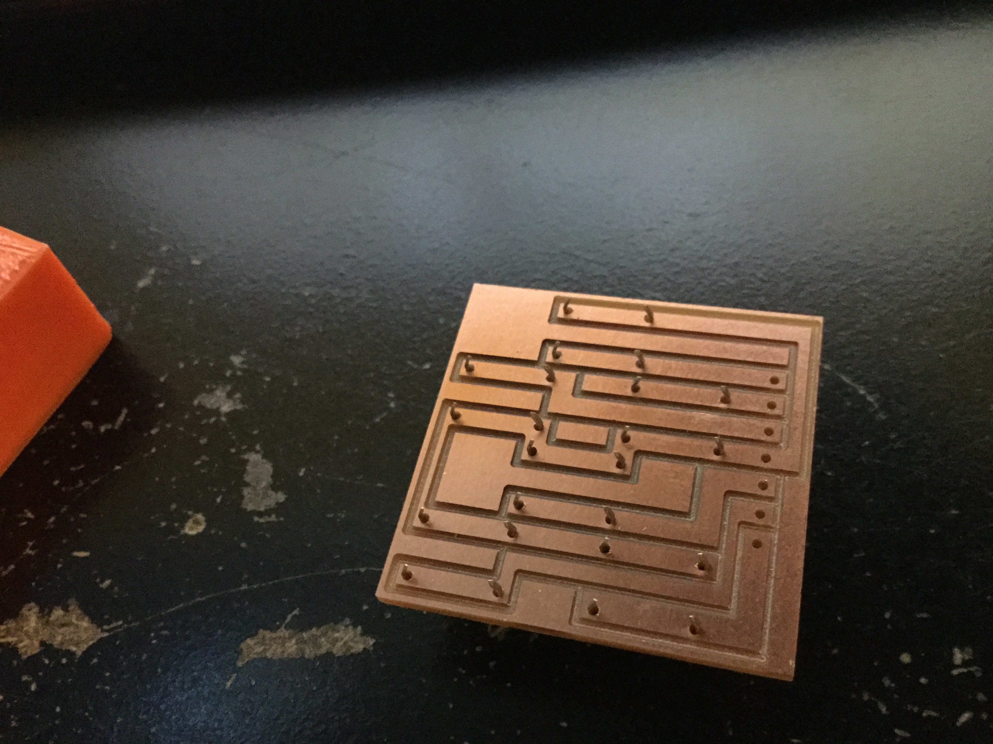
So, I designed a simple board to house the keys and etched it out. Then designed a housing for that board so I can mount it to the fixture, and printed it out. 3D printers are so freaking handy. I went from designing the board and housing to having a physical product in just a few hours.
I havent done any code for it yet, but I imagine that I will add a command that will disable the board inputs when you start etching a board, and it will enable itself during the bit changes and when the board is done being etched, all other times it will be enabled to allow you to control the steppers without having to be at the PC.
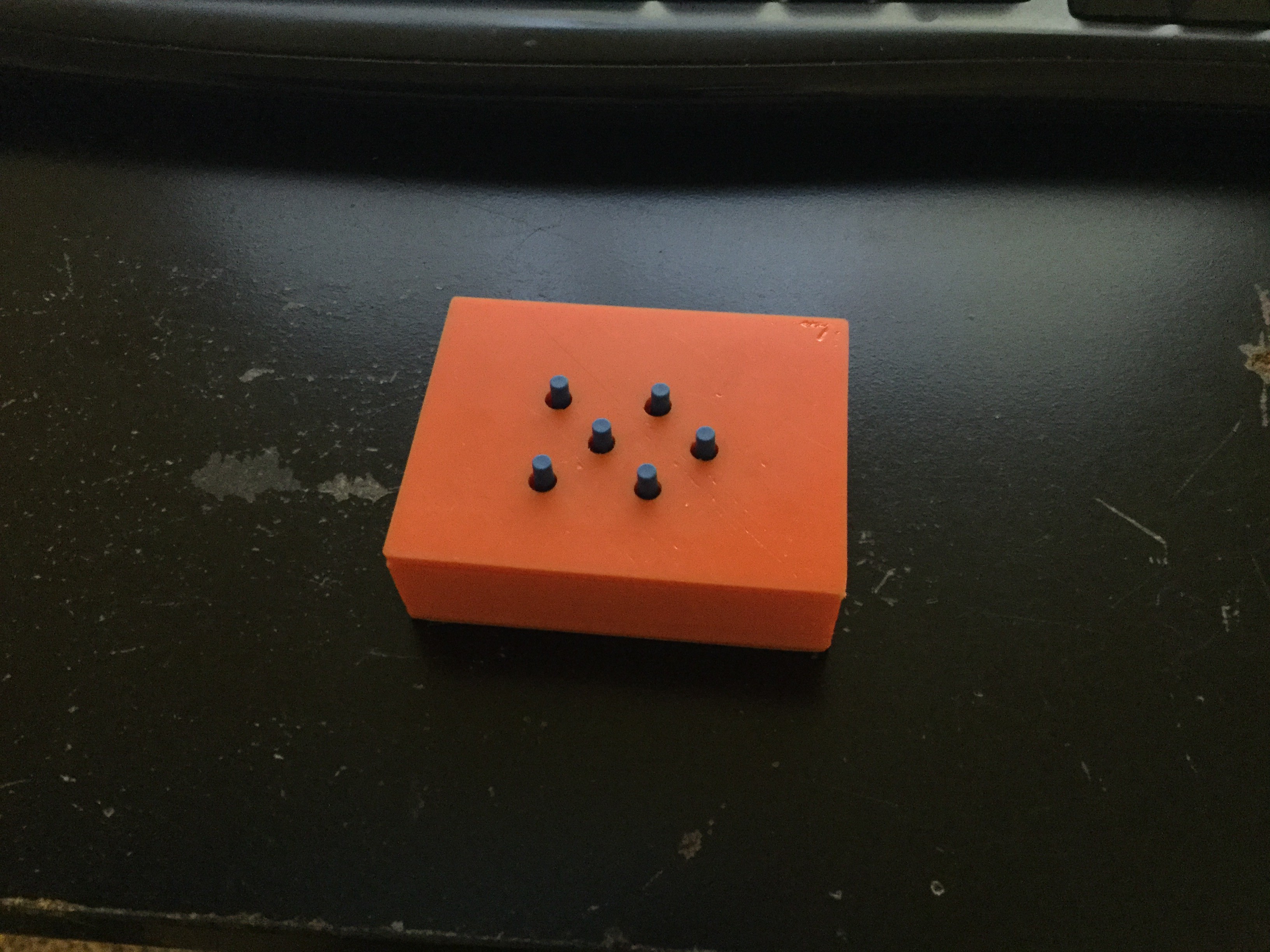
Below are pictures of the yet to be labeled product. The left two buttons will control the Z axis, and the 3 in the cross formation will be the x and y.
Maybe I should have included an indicator LED to show that it is enabled for input? Maybe in the future.
Discussions
Become a Hackaday.io Member
Create an account to leave a comment. Already have an account? Log In.