dnk17
dnk17A student in my son's middle school enrichment program was trying to build Adam Fabio's Apple ][ emulator and was have some trouble. The student was having two primary issues with the project, and both were related to exactly how to hook the hardware up.
The first issue was what pins to connect the keyboard to an the second was the pinout of the vga connector and how it should connect to the Ardunio.
What follows is basically cut and pastes from my emails with the student. while everything may not be 100% correct, my thought is that if he understands the basics, then details will follow easier.
Getting the keyboard to work.
First you need to make sure you are using a PS-2 and not a USB one. The PS2 keyboards are pretty old and have a round connector vs. the square one on USB ones. The pins you need for the keyboard are [1] keyboard data, [3] ground, [4] +5V and [5] clock
Pins 3 and 4 need to be connected to power the keyboard (make sure the polarity is correct).

The way the keyboard sends data is one bit at a time (I think you have learned about binary and hexidecimal already ?).
When you press a key the keyboard starts toggling the clk line high to low and starts sending data out the data line one bit for each clock transition.
So the arduio looks at the clock line, and every time it goes low, it then looks at the data line. If the data line is low its a 0 and if its high its a 1.
So after 8 clock transitions (low to high to low) the arduino has "read" in a single byte. Once you get all the bytes you need to have the message that tells you what key was pressed.
Now where do you connect these? Since the code tells the microcontroller what to do you can often pull this information out from the code. Looking through the code, there are some great hints.
The very first is the #define at the beginning of the code.
Usually there is a function that will initialize a certain hardware component. So if we look in the keyboard.ino file near the end there is a function called keyboard_begin.
// clock must be on digital 3
void keyboard_begin() {
  pinMode(3, INPUT_PULLUP);
  pinMode(KEYBD_DATA_PIN, INPUT_PULLUP);
  attachInterrupt(1, keyboard_bit, FALLING);
}
Here we see the pinMode command used twice, once for pin 3, and once for pin KEYBD_DATA_PIN, both are set to be pullups, so it is a good guess that these are the two pins we need (clock and data). The question then is which is which?
At the beginning of the code the is a line
#define KEYBD_DATA_PIN 4Bet that means that arduino digital pin 4 is the data line :)
And that would then mean that digitial pin 3 must be the clock.
Another hint is the following line
attachInterrupt(1, keyboard_bit, FALLING);
What this line does is attach a digital pin to what is called an interrupt. An interrupt does just what it says, it interrupts the software when an event happens.
The above line calls function keyboard_bit, when interrupt 1 falls from a high to a low.
Based upon the Arduino reference documentation interrupt 1 (int.1) is connected to pin3 on the UNO.
| Board | int.0 | int.1 | int.2 | int.3 | int.4 | int.5 |
| Uno, Ethernet | 2 | 3 | ||||
| Mega2560 | 2 | 3 | 21 | 20 | 19 | 18 |
| 32u4 based (e.g Leonardo, Micro) | 3 | 2 | 0 | 1 | 7 |
so this all checks out.
So at the end of the day
| Name | PS2 | Arduino |
| Data | 1 | D3 |
| No connect | 2 | |
| Ground | 3 | Ground |
| +5V | 4 | +5V |
| Clk | 5 | D4 |
| No connect | 6 |
Getting the VGA to Work
Some hints to help with setting up the Apple II video
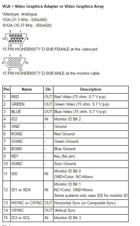
First thing is figuring out which pins to connect the VGA cable to.
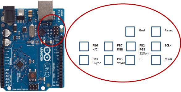
On his page he has this diagram and that’s about it for how to connect the vga cable (unless you want to look at the assembly code for the vga driver).

So I think this might be where you got stuck with not being able to find some of the pins.
But at the end of the day, this and some ingenuity is all we need to figure this out.
From this picture we know the pins we need from the Arduino is PB2, PB7, PB4, PB5, and ground. We get that from his drawing. A little investigation
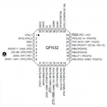
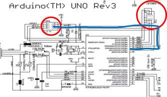
To find out where they are connected on the actual PCB, you have to trace the pins from the micro to the header.
PB2 is on pin 16 of the micro and is on the line called MOSI2 and connected to pin4 of the ICSP1. Do the same thing with PB7,PB4 and PB5 and you find that they are on JP2. Now here is the frustrating part, I couldn’t find a mapping from the schematic to the pcb anywhere on the net. So I used a meter to ohm out (that is when you use a multimeter set to measure resistance. You put one probe on one pin and then you check all the other ones until there is zero resistance between the probes. Then you know the two points are connected.)
So I did this and here is the physical mapping.
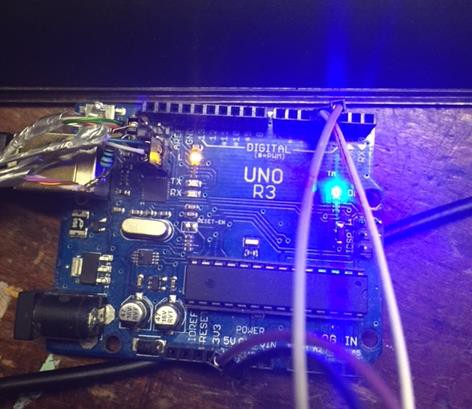
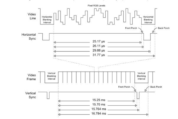
If you have access to an oscilloscope you can verify things before you wire everything up.
Couple of additional hints.
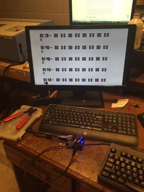
Make sure that you keep the unshielded part of the wires short. Twist the RGB wires together, along with all of the ground wires, Keep the sync wires separate and maybe even twist a ground wire around each one separately. Lastly try a couple of monitors. I got it to work on only one of the two lcd monitors I tried it on.
Also, the keyboard can be flaky, based upon the rough timing In the software. Mine would sometimes not take certain key presses.