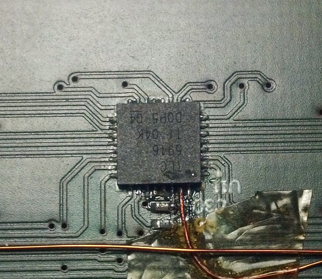
Never ever ground pins underneath a chip! When you discover that you really do need the pin that you just grounded, reworking the PCB becomes a major pain in the keister.
As you might have guessed, I didn't read the datasheet for the LED drivers carefully enough. Apparently they operate in a oneshot mode and the PWM counter has to be manually reset with a pulse on the blank pin every 4096 cycles.
I'm not the only one discovering this the hard way: http://e2e.ti.com/support/power_management/led_driver/f/192/t/199870.aspx

Oh well, I de-soldered all the drivers, cut the gnd traces, re-soldered the drivers and added the jumpers to one of the processors spare PWM outputs. It was not an easy task on QFN packages with 0.5mm pitch, I don't think I could have done it without the high power stereo microscope at work.
 Peter G
Discussions
Become a Hackaday.io Member
Create an account to leave a comment. Already have an account? Log In.