Close
0%
0%

StrobeTuner

My version of the most accurate musical tuner idea.

Similar projects worth following
A strobe tuner is a device helpful in tuning musical instruments, working by modulating the brightness of a light source illuminating a spinning stroboscopic disk. Unlike many others, a strobe tuner produces a very accurate and instantaneous readout.
A Peterson AutoStrobe 490 costs $729. For a LED and a motor? C'mon! Let's make a functional equivalent for under 1/10 of that cost!

A long time ago, me and my girlfriend (a percussionist) decided we want to build a vibraphone. The reason behind it is very simple: The cost of a complete instrument is prohibitive, and used vibraphones are seldom available - if ever. An instrument like that consists of a frame, aluminium bars or "keys" and pipes called resonators. Nothing that cannot be made out of wood, aluminium bars or pipes.

Then, by a blind stroke of luck, I found a set of vibraphone bars quite cheaply available on line. Two bars were missing, but I believed that while it might be too hard to make a full set, making just two might actually be possible.

After some research I found the main difficulty in making a bar is definitely its tuning. The reason is the process must be very accurate (definitely sub-1Hz) for the instrument to sound good. Another thing is the bars vibrate in multiple modes: the fundamental, lowest frequency mode determines the perceived pitch, and the higher modes are responsible for the overtones which shape the timbre of the sound. Vibe bars are commonly tuned in the fundamental and first two overtones. The bar has to be ground down in specific places to alter the frequencies of the modes. This topic has well been documented by the marimba builders, who shape the bars out of rosewood. A specific interval, or frequency ratio, between the modes has to be preserved for the piece of vibrating metal to sound like a vibraphone!

The first method of tuning is to do so by ear, comparing the sound from some software generator and from the bar itself. This had to be ruled out, as my ears can only detect a couple of cents of a difference - not really enough!

Another method is spectrum analysis. It might really work, but when it comes to sub-Hz intervals, analysing the spectrum in very narrow intervals requires a sound sample of significant length. This makes it impossible to view the readout instantly.

Yet another way would be measuring the frequency electronically. Still the basic drawback of spectrum analysis remains: To find a frequency to 0.1Hz you have to count the pulses for 10+ seconds. The bars do not resonate that long, especially in overtones.

Then I found out about strobe tuners. They are the titans of the tuner industry: There ain't a tuning job a strobe tuner cannot do. The response is real-time and the accuracy reaches below one-tenth of a cent. Also: They DO work in the presence of other noises. Invented around 1950 they haven't been outclassed by any modern method so far. Drawbacks? There's just one. PRICE. They are expensive, made by sigle company (Once Conn, now Peterson), eager to refresh its patents and capitalize on the same old idea over and over. So what is that million dollar idea? The principle resembles setting the ignition on older cars, or adjusting the speed of a turntable. Instead of measuring the tone, we generate it very precisely (simple in electronics world) and use it to spin a motor with a striped pattern. Then, a simple LED modulated by incoming sound of matching pitch should make a pattern appear still. Hey, it sounds like a project!
  • 3. Finalizing the hardware

    eletrax06/14/2016 at 14:14 0 comments

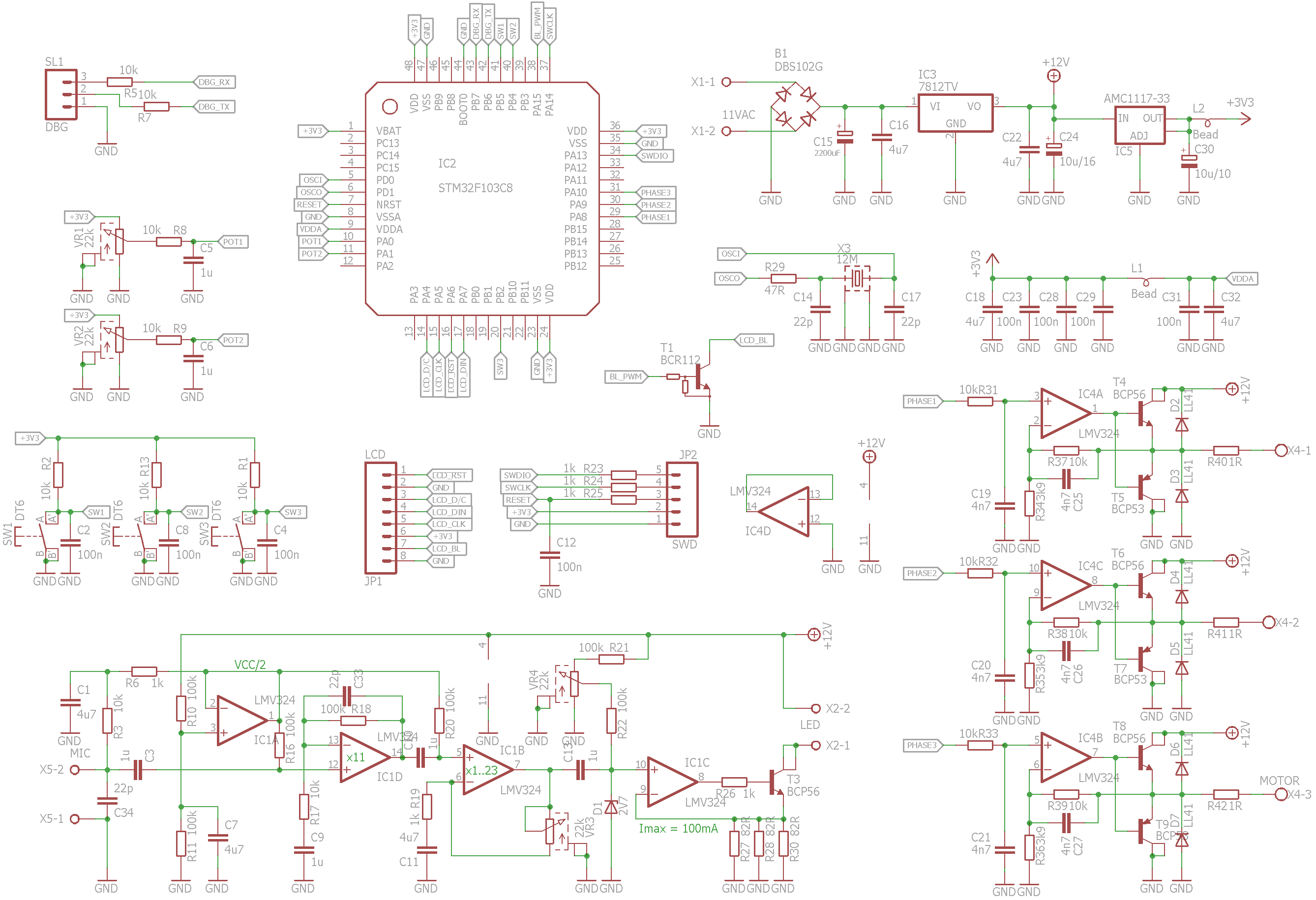
    Having settled on the motor and LED controlling circuits, we need to add some form of user interface. Hacker community popularized the PCD8544 LCDs as a cheap, readable display, perfect where HD44780 LCDs are just too limited, and small size is a nice benefit. To make things even better, lots of excellent libraries have been written for it, it takes 3.3V logic and power - same as STM32s, and Chinese sellers offer ready-made modules with built-in backlight LEDs for very good prices on eBay. We're going to need some controls for pitch being tuned - I chose a potentiometer, which will be read with STM32's ADC. It provides a simple, intuitive control. Another potentiometer will be used to control pitch offset in cents. Three pushbuttons will complete the UI part, allowing us to implement some menus in a simple, up/down/select fashion.

    As the brains of the project, STM32F103C8 is just what the doctor ordered: It's fast (72MHz, 32 bit) so it will easily churn out the exact tone frequencies. It has lots of peripherals, out of which we need:

    - 3 PWM channels for motor control

    - 1 PWM channel for backlight control

    - 2 ADC channels for potentiometer readout

    - 1 SPI for LCD

    - .. And a few GPIO's.

    The microcontroller will be clocked from a 12MHz crystal, to function as an accurate frequency reference.

    The power supply section is very simple, it consists of a rectifier/filter and a pair of voltage regulators, providing +12V and +3.3V for all the circuitry.

  • 2. The LED driver

    eletrax06/14/2016 at 11:23 0 comments

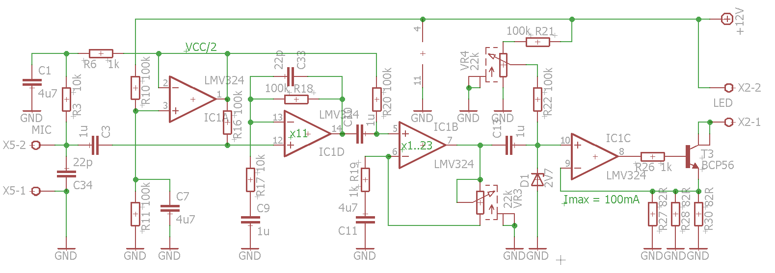
    The earliest strobe tuners had used neon lamps to illuminate the strobe disk. In the 1950's they were the only electric source of light capable of being modulated with fast audio signals. Today, the obvious choice is a LED. As I planned to make the strobe disk quite large (~120mm diameter), I decided to use a 1W (350mA) power LED. Not to be confused with Peterson's reddish-orange, I picked my favourite colour: deep, InGaN green.

    It simplifies things a lot that the LED intensity depends rather linearly on the junction current. To modulate the LED brightness all that we need is a current source, made out of an op-amp and a power transistor. Another two op-amps amplify the audio signal, and the remaining fourth op-amp is used to generate 1/2 Vcc voltage to bias the amplifying stages and the electret microphone.

    Zener diode D1 limits the maximum instantaneous current source control voltage (rather non-linearly, but hey, it works).

    VR3 potentiometer adjusts the level of gain, and VR4 controls the LED idle current. To be honest, after some testing I found I could do without VR4..

    ..but hey, one never has too many knobs and buttons.

  • 1. Motor selection and control

    eletrax06/14/2016 at 09:55 0 comments

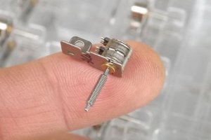
    The heart of a strobe tuner is the strobe disk, driven by a small electric motor. It has to spin pretty fast (thousands of RPM), but the only mechanical load is inertia and air drag. The angular speed has to be very accurate and stable. These requirements sound very familiar: After all, a CR-ROM or HDD spindle motor does exactly that. I also had plenty of HDD spindle motors. By coincidence, one of them fits exactly in the center hole of a transparent CD I found in a cake box of CD-Rs some time ago. Two birds with one stone!

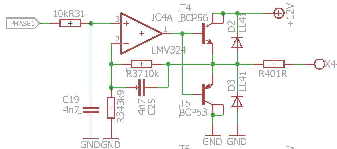
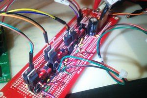
    Still I was a bit worried about using a BLDC motor: The sensorless motor control scheme is quite complex, and it would be hard to write a good PID regulator, able to maintain the speed with required precision. However, a BLDC motor can be treated like a 3-phase synchronous motor and fed with three sine waves 120* apart. Then all that is left is to make a precision 3-phase sine generator. Of course it would be possible to perform switching with a trio of MOSFET half-bridges, but this technique creates a lot of electrical noise, which might affect the sensitive analog part of the tuner, so let's be gentle and go with the sine. At 1-2W of power, there's no reason to be super energy efficient in a stationary application.

    Initial considerations gave me faith that everything will be possible on a STM32F103C8. Generating a sine wave on a microcontroller is possible with a technique called DDS (more on that later). Some F103's have a twin channel DAC, but I need three channels. Fortunately, STM32's have many 16-bit PWM channels, and adding a RC filter to a PWM channel makes it a poor man's DAC. Now, for 3.3V powered MCU our DAC is able to produce a voltage from the range of 0...3.3V. Most HDD and CDROM motors are powered from 12V. So we need to amplify the signal about 3.5 times. The motor requires some hundreds of mA of current, so let's add some medium power transistors - and voila, we have a motor driver! Simple, cheap and hacked together, but it should work.

View all 3 project logs

Enjoy this project?

Share

Discussions

markus.almroth wrote 01/24/2022 at 16:51 point

Yes! Did you finish?

  Are you sure? yes | no

mike vidal wrote 12/31/2016 at 17:15 point

I'd like to build this project.  Do you have any updates?

  Are you sure? yes | no

Similar Projects

Does this project spark your interest?

Become a member to follow this project and never miss any updates