Close
0%
0%

Lino

An Arduino-compatible board to master the power. The first attempt of a compact dev-board capable to drive 10W loads.

Public Chat
Similar projects worth following
A board designed to provide high power and the proper control, in order to drive devices with high power requirements, like power LEDs and motors.

I needed to design a small board with a proper power handling all in one PCB, to be put in a small box, and from there control my power LEDs. The fastest solution was to design a small and as compact as possible proto-board to develop my firmware. Just a simple development board.

Here is why Lino is born. And to let me experiment with other commercially available boards and hobbist projects, I made it Arduino compatible in hardware. Lino is the LIght arduiNO.

Lino can handle 4 independent PWM channels, provide a power budget of up to 10W from an external power supply and up to 2.5W if powered and controlled from an USB port.

I am playing with LEDs for few month and during that time some little projects were born, but now I need a system to handle the logical part and the power distribution. I simply just can't use an Arduino board, or any other development board: I need a proper power handling embedded in a small space, all in one PCB, with some particularly high power requirements. And being Arduino compatible. This is Lino.

It will be used to power up the Glighter-S modules in a compact fashion, finally reaching something similar to a complete lighting working system.

Project purpose and board review

This board is designed to power up any power LED, motor and/or anything which requires up to 10W and can be controlled in PWM. Lino supports in hardware the control through physical, glitch filtered, inputs like buttons and encoders.

In the picture below is shown the board with its main interfaces:
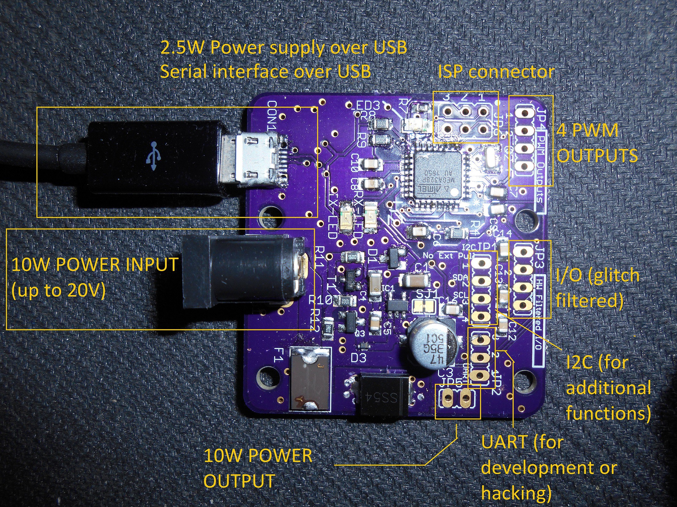
More protocols are supported onboard, like I2C and UART (real or through USB emulation). With the proper firmware running on Lino, terminal commands are supported using the serial protocol, connected with the Atmega (the main MCU) mainly in two ways: with USB through an emulated terminal, or directly with the microcontroller's UART, supporting then any communication with a serial device, like the ESP8266 and with no additional circuitry, since everything is working at 3.3V.

Since this board can communicate using UART or I2C, this setup is scalable, making it capable to drive more Lino boards connected with each other.

Board characteristics: the union of Atmel and Microchip in practice

Here is shown the main blocks of the board. It is a kind of celebration of the acquisition of Atmel from Microchip. It is used an Atmega328P microcontroller and the Microchip MCP2200 USB to Serial converter instead of the FTDI, which instead would costs truly a lot.

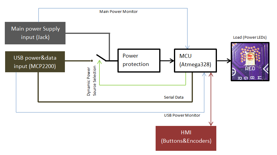
Below, the block diagram of the project and a picture which shows where physically things were arranged on the board:
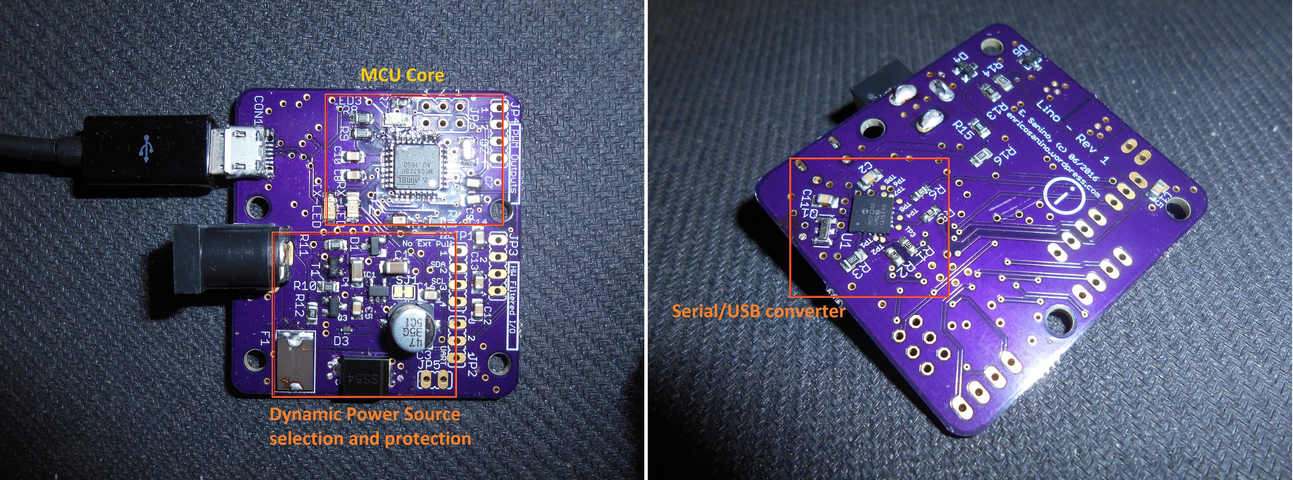
Everything is almost self-explaining. Briefly, the HMI (Human-Machine Interface) can support a single Encoder with an integrated button to minimize the commands and user interface complexity, but with firmware mods can be anything else. The load used to test the Lino board are 4 Glighter-S power LED drivers, which are lighting up a LED satellite, all these test boards are designed in Glighter-S project page.

The controller core is the Atmega328P, which is used to keep the hardware Arduino compatibility. With the low cost and well supported Microchip MCP2200 I can obtain a neat working system interfaced with any PC or serial device: in fact I have also a pure serial connector, with 3.3V voltage swings. For example it can talk with the famous ESP8266 with no additional circuitry.

A bit of more explanation is instead necessary for clarify the power handling.

Dynamic power source selection

The selection is performed by the MCU (green dashed line in pictuire below), while a default safe state is kept when the MCU is not driving the switch. All the voltages are monitored, in order to allow the firmware to make the right selection. The priority of the source selection is given to the external power source.
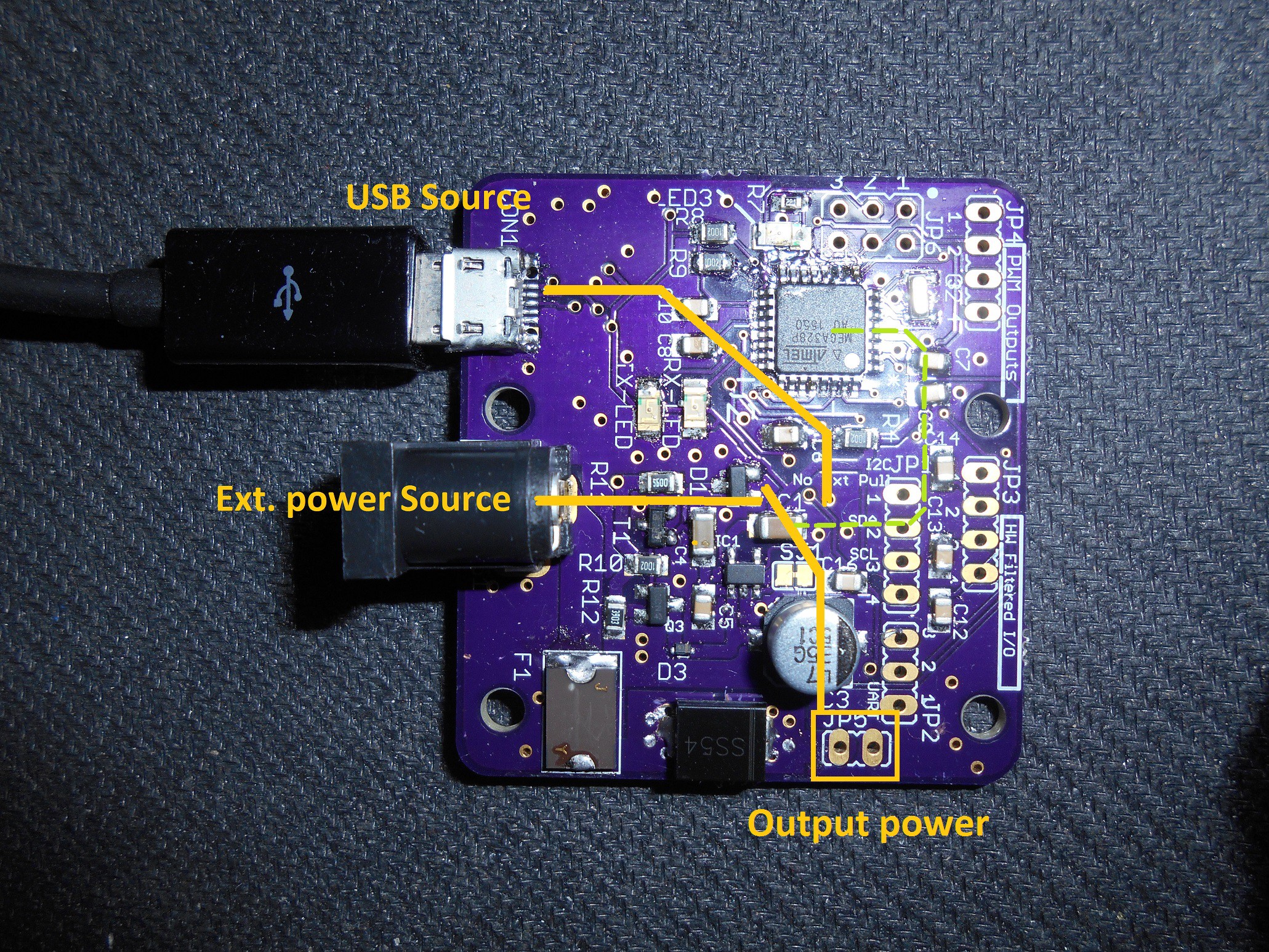
The USB power is limited, since this board can be used directly connected to a PC, able to provide, normally, no more than 2.5W per USB port. Therefore, to use the entire power capability, an external power supply shall be used.

Due to the extremely high input voltage range, the power source selection is achieved in the firmware while the hardware is fully protected against misbehaviours and short circuits. After all, it is a personal project and burning a board is tedious and I can't afford this, prevention is better. As also in professional environments, anyway.

Below just a brief of the supply characteristics:

Electrical characteristicsMinMax
Input voltage3V20V
Maximum supported power (USB only)2.5W
Maximum supported power (Power Jack)10W
Maximum supported power (Power Jack + USB)10W...
Read more »

  • Using the board #2: [video] test the protocol with Python

    Enrico09/09/2016 at 20:38 0 comments

    The test load

    The load is made by 4 Glighter-S that are powering as many power LEDs. I grouped them in a proto PCB like in picture below:

    DSCN6151.JPG

    These 4 boards are simply connected to the same power line, with 4 control wires that are connected th Lino. Each of their output is connectet to a single LED, with the result of 4 LEDs in total driven singularly by Lino.

    The finger test

    Now, moving to the board that actually carry the LEDs, I felt the need to change some things. When doing my math, I realized that a small heatsink could work keeping the LEDs cool enough to keep them alive, as you can see here:

    sat_back_no_led

    This "cool enough" is not enough to pass the so called finger test: this test is considered to be failed if you can't stand a finger on the heatsink or any surface. If this happens, we are likely more than 65°C, depending on what is it your job, if you are a farmer maybe you have thicker skin and maybe you are sensible to higher temperatures.With this one, we are passing 80°C using my IR thermometer. My finger is definetely hopeless.

    Since the heatsink actually shall be touched during the usage and my finger must not be burned, I needed to ovesize the heatsink itself. With a new one, the maximum temperature rise to no more than 60°C, and I extend by 20°C more the ambient operating temperature range of the LEDs:

    DSCN6155.jpg

    As you can see, I need to think about the shape of the heatsink and the PCB. But for this test, what's in the picture is acceptable.

    Turn on the board

    The board can be driven using the USB/serial or with a single encoder. Herein I will show the serial test, and to generate the correct data pattern to be sent on the board, I wrote a simple Python script to simplify the testing. It uses Python 3+, exploits the pySerial and Tkinter module. Basically the Tkinter lib generates an HTML compatible color code and will be arrangend to an array sent throug the serial line, here emulated on USB. At every complete frame received, Lino will apply instantly the requested color. In other words, when receives the "stop character" described in the Lino protocol.

    Here the complete assembled configuration, where the power supply is given from a 9V - 1.5A DC power supply that will be connected to the board.

    DSCN6158.jpg

    Let's connect the DC power jack and the USB to the Lino and to a PC running the Python script demo available in the project links. Run the script with Python 3.5+ and the following will be opened:

    python_color.JPG

    Just type the available COM that appears when you connect the board, a space mark and write the communication speed used by Lino. Press enter and the following appears:

    python_select.JPG

    It is in italian, but it is the intuitive and dummy default color table provided by Windows: select the right combination and press OK. Lino automatically displays the colors on the LEDs.

    Shades of white

    Note that it is implemented a white adjustment computed directly by the Lino's microcontroller, the white component that controls the white LED it is not generated by the script: when all of the RGBs are greater than zero, there is a bit of white that will be reproduced using the fourth pure white LED, making it more realistic with respect the expectations. In this way I can generate any kind of white light shade. Awesome.


    Setting-up the prototype

    To set up everything and test it in a more compact way, I thought to use a PVC panel. But at the moment they were missing. So to finish in the same day, I remembered that I have kept a light guide plate from an old LCD panel. I knew that wasn't trash!

    A light guide plate is a panel (in acrylic like material) with some dots that are intercepting the light from the side backlight and redirect, guiding it, it to the LCD, actually rotating the light path by 90° towards the LCD panel:

    light_guide_plate.jpg
    (src: geek.com)

    Then I have realized too late that I could make a photo before cutting the plane, so here is what remains of my panel, already cutted, bended and somehow abused:

    DSCN6172.jpg

    Exactly, ...

    Read more »

  • Using the board #1: Lino "protocol"

    Enrico06/25/2016 at 18:06 0 comments

    The "Lino protocol" - Board demo interface

    To have the board working, I setup a simple protocol used over the serial, but other physical line can be used, like I2C. I need to master even complex variations of the PWM sequence, also in a scalable way. For this reason I needed a proper protocol, with expansion potential, to open the possibilities to develop a proper higher level application in a simple way on a PC or any master controller side.

    Moreover, as it will be explained, the data handled by this protocol is conceived to be developer friendly, where the developer is someone who will generate a proper software to achieve the desired data exchanged.

    What is important here, is that we have 255 combination per each color, plus an algorithm to emulate in RGB and pure white combination to generate pastel colors or shades of white. With such assumption, I do not use any LUT but instead I generate the color according to the HTML encoding executed on the Lino microcontroller.

    Physical Layer

    It consist in an array of 18 bytes sent from a master PC or device (over serial/USB) made by the following sequence, from the first to the last byte sent, MSB to LSB:

    [StartChar] [CTRL#00] [CTRL#01] [R#0] [R#1] [G#0] [G#1] [B#0] [B#1] [W#0] [W#1] [INT#0] [INT#1] [RES#00] [RES#01] [RES#10] [RES#11] [EndChar]

    Where each byte is represented from LSB to MSB, the data is sent using UART (8 bits, 1 Start + 1 Stop bits, no parity), but can be transferred using any other simple protocol (I2C, SPI ecc).

    Serial voltage levels swings are on 0V-3.3V.

    Data handling

    The values inserted by the application or the user through the terminal are written in ASCII, but representing an hex format coded to save bytes. In other words, if the sender wants to send the value 254(decimal) to Lino, it will send the chars "F"(character) and "E"(character) or "f"(character) and "e"(character) on text terminal, representing the intention to send the 0xFE hex value. The first char sent is the MSB of the hex number; how each bit is transmitted is no more concerned here, but hidden in the physical layer described before, handled in UART. The chars sent are corresponding to ASCII codes, so on the serial lines are physically sent, in this example, the ASCII "70"(decimal) (for letter f)+"69"(decimal) for letter e.

    On the board is made all the conversion reversed to actually compose the number 254. To ease the software front-end, the serial is completely case insensitive and look only for characters that can represent the hex numvers, so any character sent outside the range "0" to "9" and from "a" (or "A") to "f" (or "F") can be used in the firmware for synchronization, or can be discarded at run time but used by the user when sending data manually over the terminal for testing purposes.

    Here below is listed the meaning of each byte:

    1. StartChar: the char used to discriminate a begin of transmission after startup, or a StopChar, after a timeout or any subsequent StartChar in case of line issues
    2. CTRL#00/#01: The combination of characters reserved for any auxiliary command. #00 is the MSB, #01 the LSB.
    3. R#0/#1: channel Red data (from 0 to 0xFF). #0 is the MSB, #1 the LSB.
    4. G#0/#1: channel Green data (from 0 to 0xFF). #0 is the MSB, #1 the LSB.
    5. B#0/#1: channel Blue data (from 0 to 0xFF). #0 is the MSB, #1 the LSB.
    6. W#0/#1: channel White data (from 0 to 0xFF). #0 is the MSB, #1 the LSB.
    7. INT#0/#1: intensity which is applied to the RGBW channels (from 0 to 0x64 [100% in decimal]). #0 is the MSB, #1 the LSB.
    8. RES#00/#01: reserved byte for any further necessity. #00 is the MSB, #01 the LSB.
    9. RES#10/#11: reserved byte for any further necessity. #10 is the MSB, #11 the LSB.
    10. EndChar: the char used to end the transmission and call the command interpreter on the receiver (Lino).

    Each group of byte (numbered as #0#1, #00#01, #10#11) can be divided using a mark char (here the ".", a dot) to make it more human readable the text on a terminal emulator, when debugging, testing and so on. These chars will...

    Read more »

View all 2 project logs

Enjoy this project?

Share

Discussions

Similar Projects

Does this project spark your interest?

Become a member to follow this project and never miss any updates