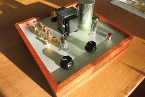
So if we’re going to design and build a tube headphone amplifier that will work reasonably well with a variety of models, what should we consider?
- Damping factor
- Properly loading the tubes
- Sufficient listening levels
- Frequency Response
- Simplicity
Damping factor is a measure of how well an amplifier controls a transducer (speaker or headphone driver). It is calculated by dividing the speaker or headphone’s impedance by the output impedance of the amplifier. A higher number generally equates to tighter bass. And who doesn’t love a tight bass? Due to their intrinsic plate resistancethrough, tubes generally have a high output impedance that we need to overcome to achieve a good damping factor. Luckily, there are a couple of common methods to lower the output impedance of a tube.
Cathode followers are able to achieve an output impedance of roughly 1/Gm. This has been used in many headphone amp designs to good effect. The de facto tube of choice for this kind of design has been the 6AS7. In a standard cathode follower configuration, the output impedance of this tube would be around 140 ohms. That gives us a damping factor of about 2 with 300 ohm headphones (not terrible), but with low impedance headphones the damping factor is way lower. For reference, the damping factor of a typical 300B amplifier playing through 8 ohm speakers is around 4 or 5.
The other approach for lowering output impedance is to use an output transformer. This is what you see in speaker amps that have to contend with 4 and 8 ohm loads. Headphone impedances are much higher than speaker impedances, which is good, but finding an output transformer with secondary taps for a large range of headphone impedances can be difficult. Luckily, headphones need very little power, so we have some leeway in selecting a transformer when it comes to reflected impedance.
Properly loading the tubesFor good distortion and power performance, we usually want our transformer to reflect an impedance of at least 3x the plate resistance of the tube. Our reflected impedance is the square of our transformer’s turns ratio multiplied by the load. For a lot of small tubes (ie the kind that would be most appropriate for headphone amps), this requires a high turns ratio if we want to use 32 ohms headphones. The same turns ratio would result in a pretty batshit high impedance with 300 ohm cans (limiting the output power), so we are going to want multiple secondary taps to keep everything within reason.
Pro audio matching transformers come in a lot of flavors for matching the output and input impedance of various studio gear. One of the common ones is 10k:150. Some of these 10k:150 transformers also have center taps on the primary and secondary, meaning we can get 5k:150 and 10k:75 impedance ratios as well. Edcor makes just such a sexy beast in WSM (½ watt) and XSM (2 ½ watt) sizes. Guess what I gots in my parts bin. The various configurations allow for a 4.2k load with 32 ohms, a 10k load with 300 ohms, and everywhere in between with other headphones. That’ll do.
Sufficient listening levelsThe chosen transformer has possible turns ratios of 11.5, 8.2, or 5.7, depending on how we configure the taps. We are going to use the whole primary (for maximum inductance), leaving us with the ratios 8.2 and 11.5 (full secondary and center tap of secondary respectively). The voltage that we create across the primary will be divided by this ratio when it appears at the secondary. A pair of Sennheiser HD600s are 300 ohms and produce 98db at 1 volt. To get this one volt on the 8.2:1 ratio tap, we need to apply 8.2 volts on the primary. Easy peasey, lemon squeezy. A pair of Grado GS1000e’s are 32 ohms and need 1 milliwatt to produce 99db. One milliwatt into 32 ohms is only .2 volts. To get this .2 volts on the 11.5:1 ratio tap, we need to apply only 2.3 volts to the primary.
To calculate the damping factor provided by the Edcors, we use the square of the turns ratio. Say we want a damping factor...
Read more » Timothy Cose


 Boolean90

 t.oster92
When the filament is off, there are no discharge path. You should consider having a bleeder resistor (a few hundred K) across the high voltage DC rail to discharge the big caps.