 Peter McCloud
Connecting a servo to throttle and choke is one of the last things to be done before the hover test. I've been taking a look at the hardware on the engine to see what's required.
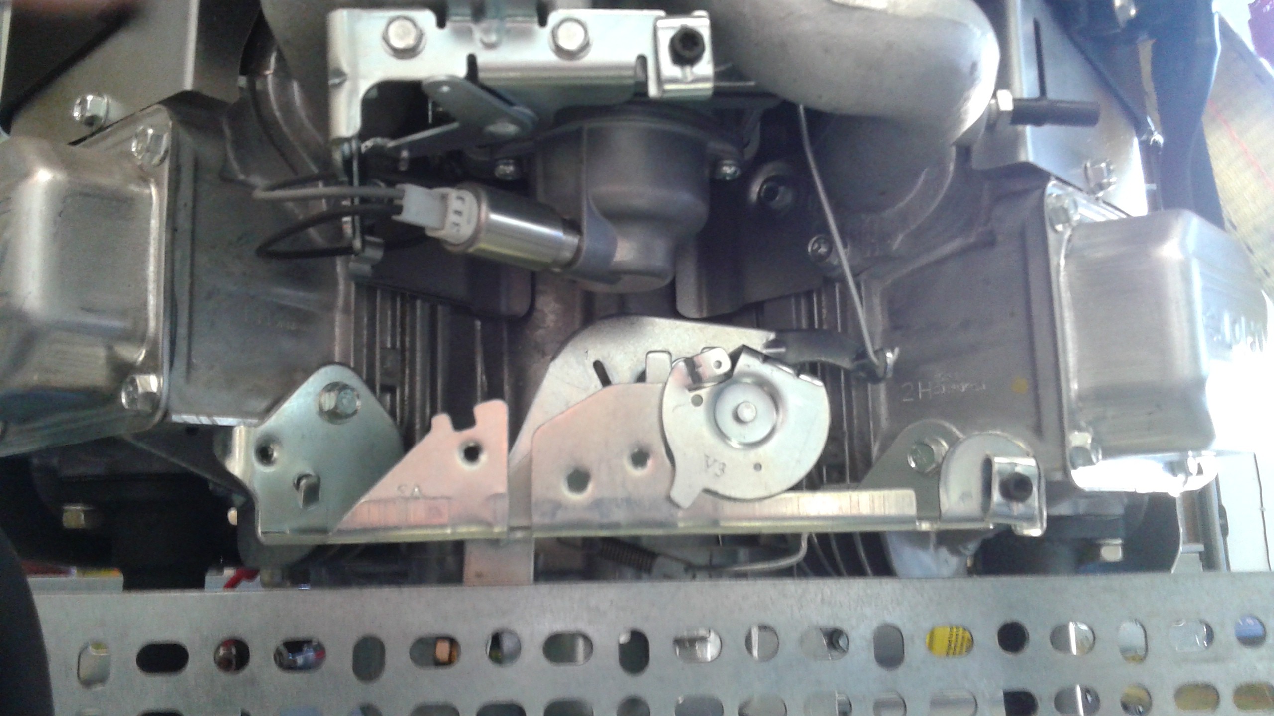
The engine user manual doesn't cover anything regarding the mechanical connections. A bit of research on the internet hasn't shed any light on the details on the throttle plate either. I know that the fuel solenoid is what has the electrical connection. The lever arm attached to the fuel solenoid is likely the throttle. That means the lower hardware where is likely the choke. There's a few springs and connections, which don't seem straight forward. The one thing that's clear is the the vertical push rod is the only part that interacts with the rest of the engine. If I'm going to just connect a servo, this seems like the best place and the rest of the hardware could just be removed.
If any one has better knowledge or access to a schematic on this, any inputs would be helpful.
Discussions
Become a Hackaday.io Member
Create an account to leave a comment. Already have an account? Log In.
My ancient 40hp outboard motor has a (currently unconnected) solenoid-based choke. Might be easier to do that then try to use a second servo for this function.
Are you sure? yes | no