1. Hardware Choice
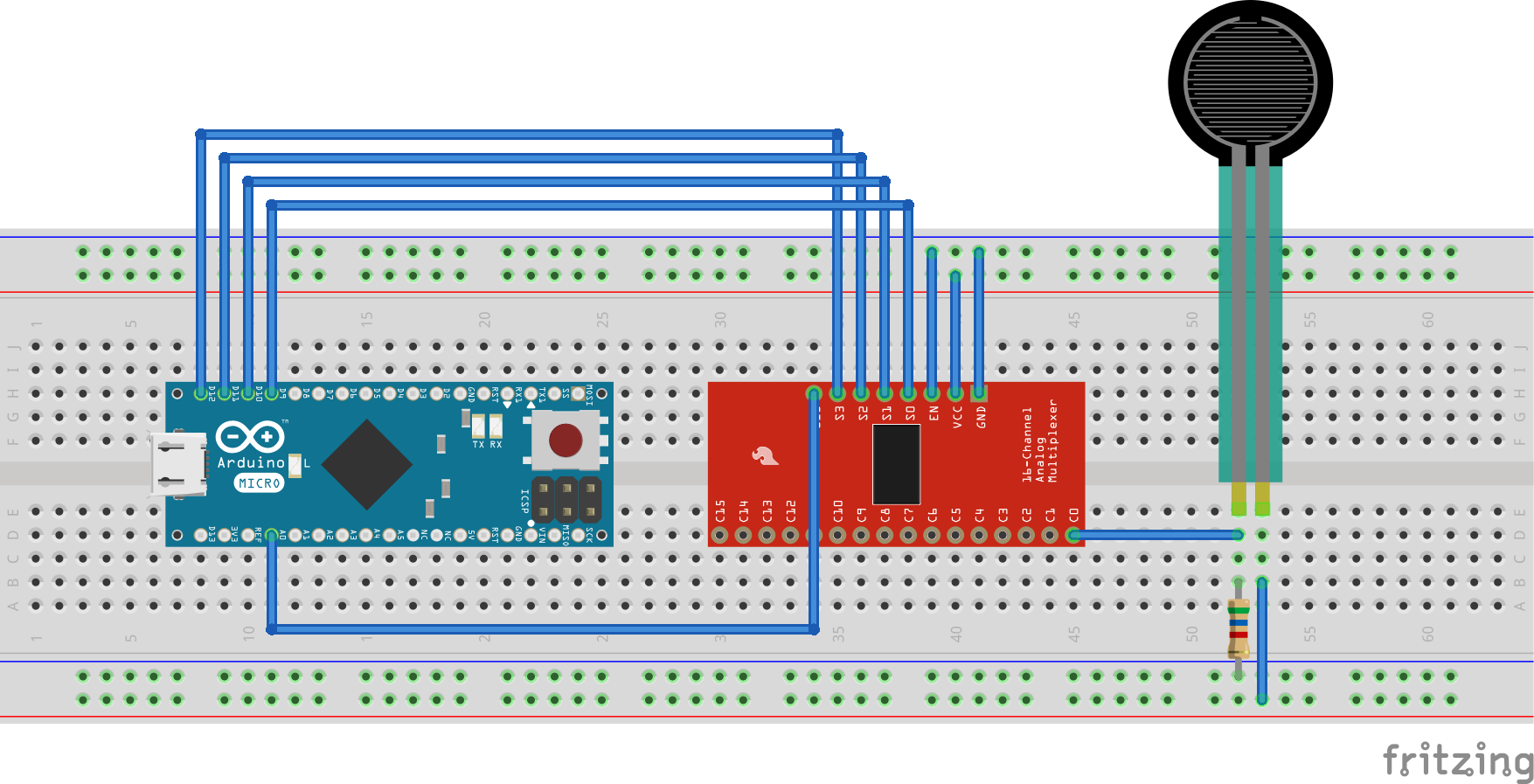
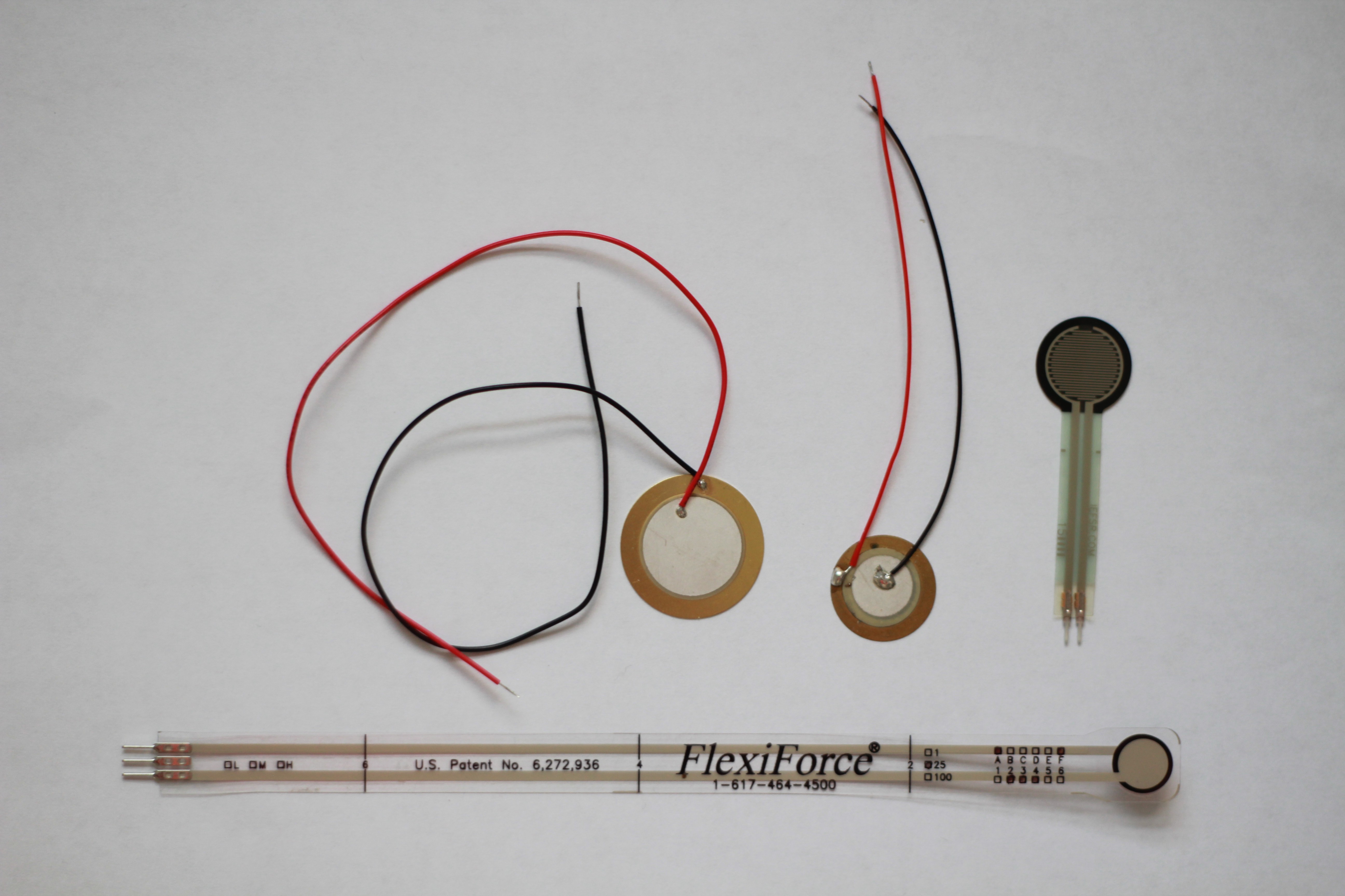
The choice of hardware was all fairly straight forward except for the sensors. In the image you can see a range of sensor which I've tested, ranging from £22.50 to £0.70. The piezo sensors (metal backing) which were the cheapest performed surprisingly well, however I settled for the FSR 400 series for three reasons. They're flexible, much cheaper than the Flexiforce and has very good documentation on the calculations needed to get a linear relationship between force and resistance. As for the rest of the hardware I don't think it's worth elaborating, I chose the Arduino Micro for it's small form factor and the HC4067 because it read all 16 sensors from one chip, pretty handy right?
2. Insole 3D Modelling
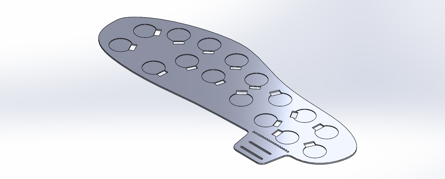
So now we've got the hardware sorted I want to explain the 3D modelling process, which was carried out in Solidworks. There's nothing particularly complicated about it but what needs consideration is the placement of the sensors and cable management.
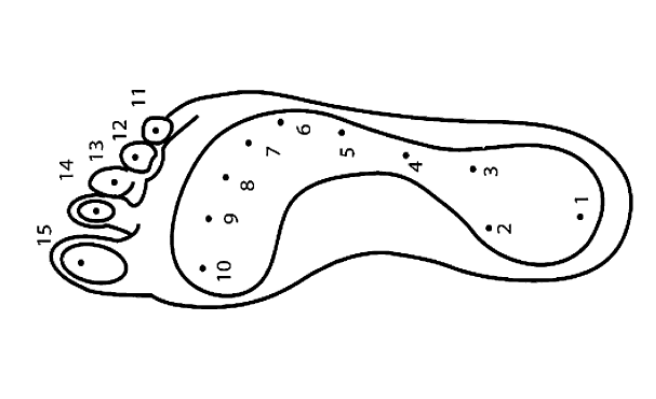
Prior to starting the project I read a number of papers around Bio-mechanics, Orthopedics and the design process of footwear. This is where I found the picture below (foot anatomical points) which I used to distribute the sensors. However the size of the sensor itself is too large to be placed on every point, therefore it took some interpretation.
In the second version (pictured below) I added a stress relief for the cable. Once printed the part is left to cool down to room temperature, after which it was removed from the bed. We then place it back on the bed and heat up to 60° which allows to bend the tab perpendicular to the sole. NOTES: Once printed it must first be removed from the bed otherwise the part will stretch whilst bending due to it sticking | Temperatures are only valid for PLA
You can find the 3D model (.stl) in the files project named insole_V2.1
3. Assembly
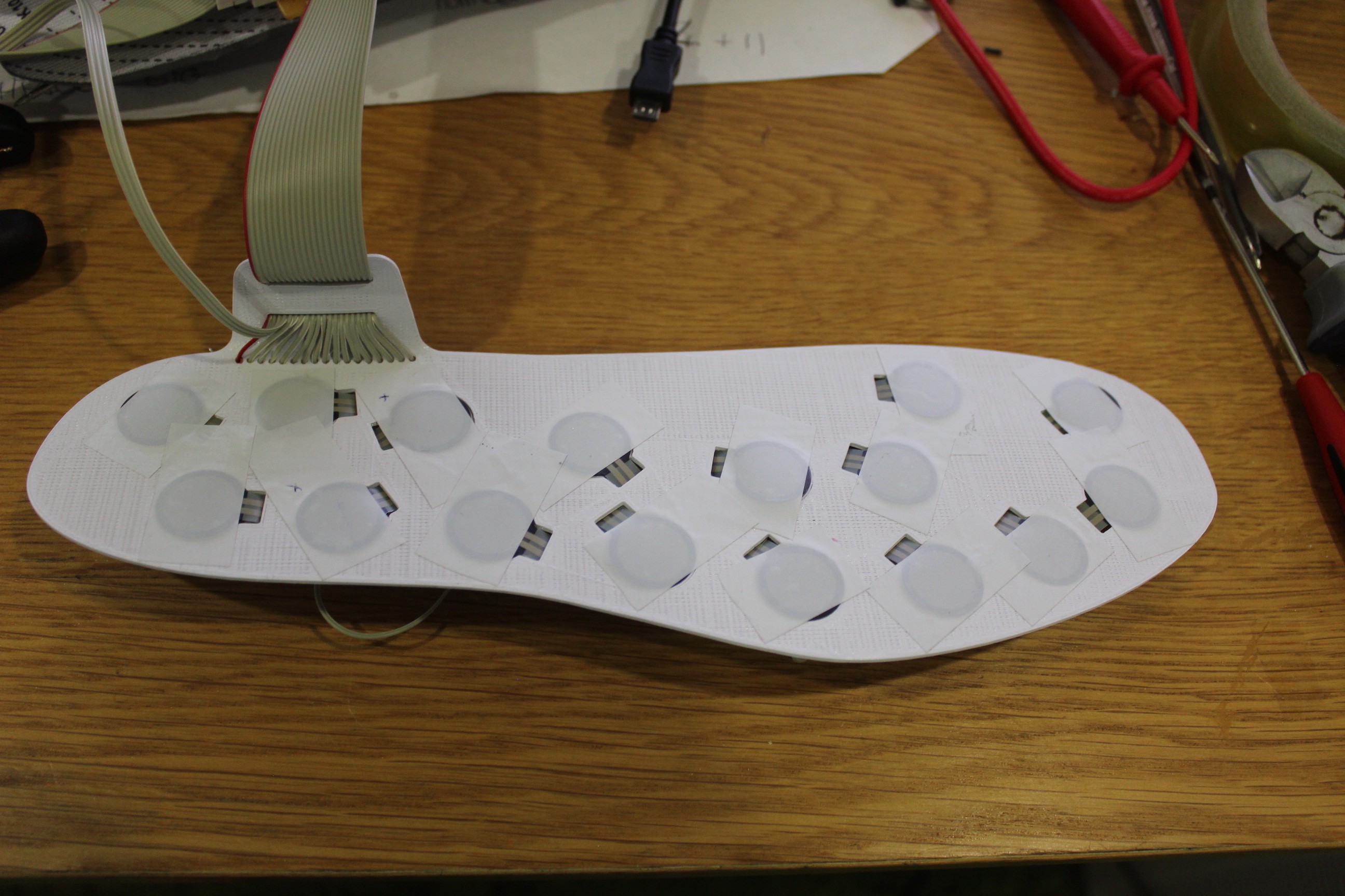
The top side turned out fairly well, I used electrical tape to keep the sensor in place for now, bear in mind this is a temporary prototype so nothing is fixed permanently.
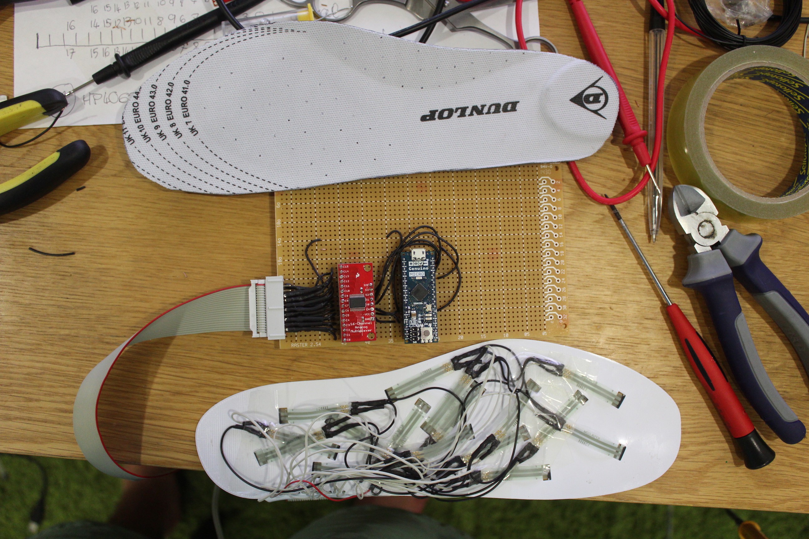
Even after a pedantic cable management planning process the first prototype is rather disastrous. The overlapping cables will probably cause the connections to fail during exercise, so I haven't and won't be testing this prototype during exercise. To solve this I'm looking at etching a PCB for the second prototype, if you're reading this and have a better solution please comment. :)
3. Extra
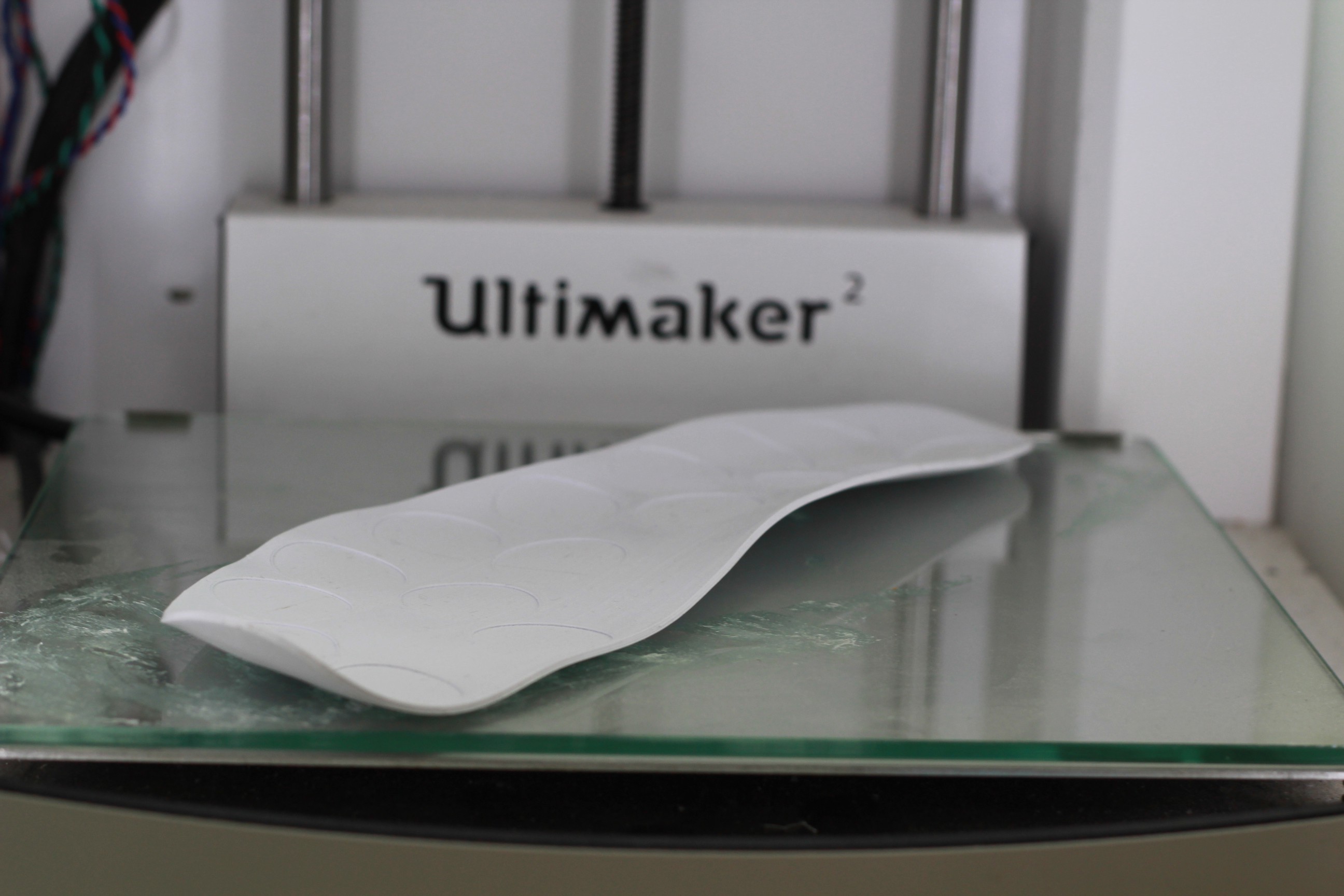
As a last note for this first update I thought I would also share an experiment which I won't be using but is interesting. The first version of the printed prototype was molded by re-heating it to 65°, placing in the shoe and putting my foot on it until cooled. It produced a very nice result however I decided against it for two reasons. For the data to be as accurate as possible the shoe must be as neutral as possible (flat), additionally the sensors are prone to giving false values when bent.
Furthermore, all the lowest points on this insole (high pressure) have a sensor located more or less in the middle, which confirms they are correctly placed. However, these insole are designed for anyone to wear during diagnosis which makes for another reason not to mold them.
Finally here's a picture of the controller itself, it's not as small as I want it to be but hopefully that can be improved in the second iteration. NOTE: the resistors in the picture below are hidden behind the HC4067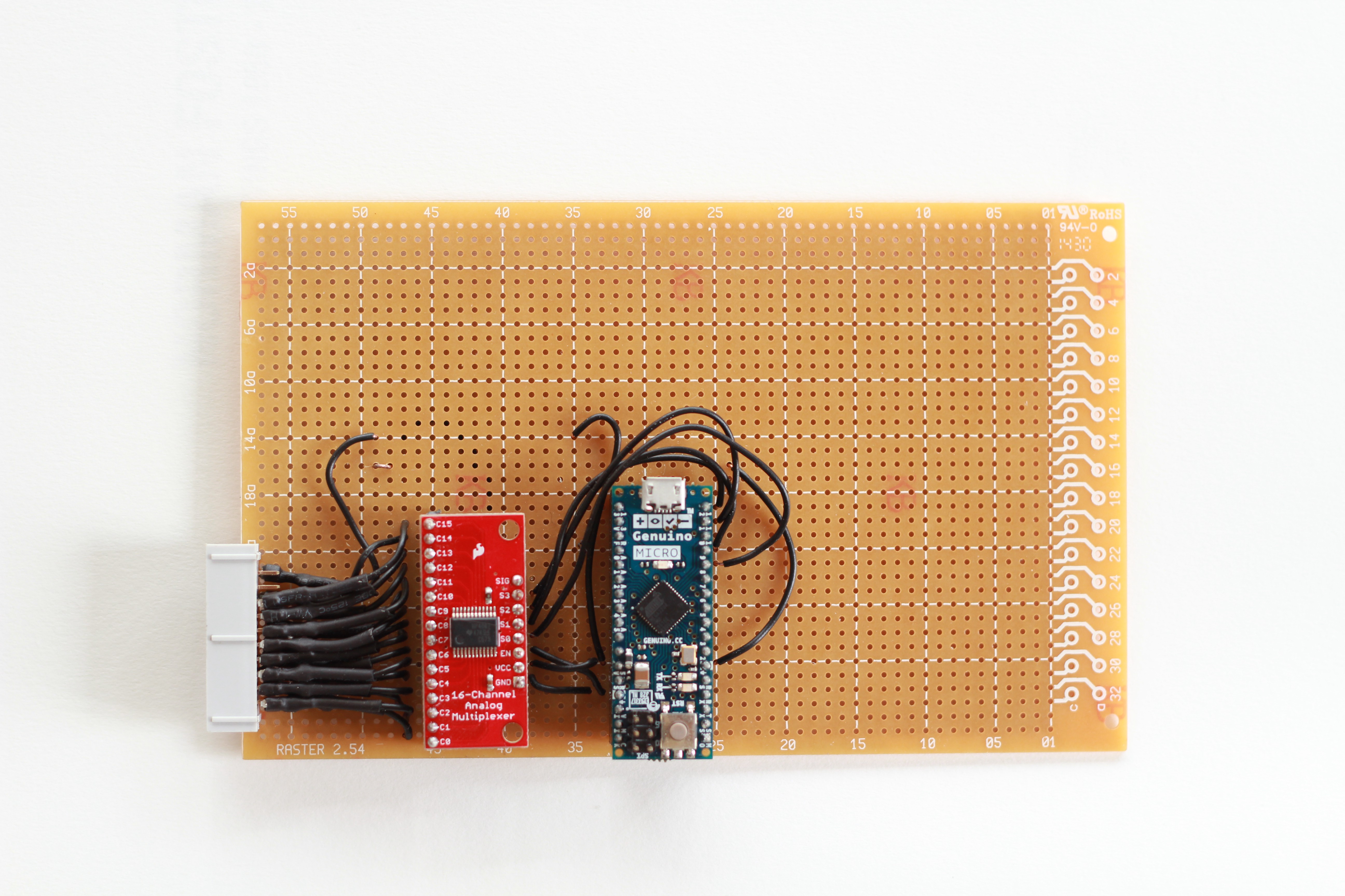
 Charles Fried
Discussions
Become a Hackaday.io Member
Create an account to leave a comment. Already have an account? Log In.