With the recent success of the OpenCT2, I'm back thinking about the coded aperture MRI again. David was also in Antarctica for a while for his radio astronomy graduate work, but he's been back and we've been chatting about MRI things lately.
The two issues: Coil Winding, and a USB ADC
When the project went on the backburner, I'd hit two stumbling blocks that seemed like good solutions would have to present themselves for before things could progress:
- Coil Winding: It's much, much more difficult to wind radio coils than it looks. My attempts to do this by hand ended in tears (and very sore fingers).
- High Speed, High Resolution, Long Capture ADC: It's apparently very challenging to find a high speed (100ksps+, ideally 1 msps+) high resolution (14-16bit) USB analog to digital converter peripheral that can also stream at least several seconds worth of data. Most have very small sample buffers (approximately a few thousand samples)
Coil Winding Machine
Just like a prerequisite for becoming a jedi is building your own lightsaber, it seems like a prerequisite for being interested in radio is building your own coil winding machine. Radio coil winding seems like a somewhat lost art (I'm sure if this was a century ago, I'd know a dozen folks who were expert coil winders), but youtube has no shortage of videos of folks who have put together their own machines. It seems that one can also purchase manual coil winders fairly easily, but they tend to look ancient, and like one could come up with an automated design in a few evenings of work.
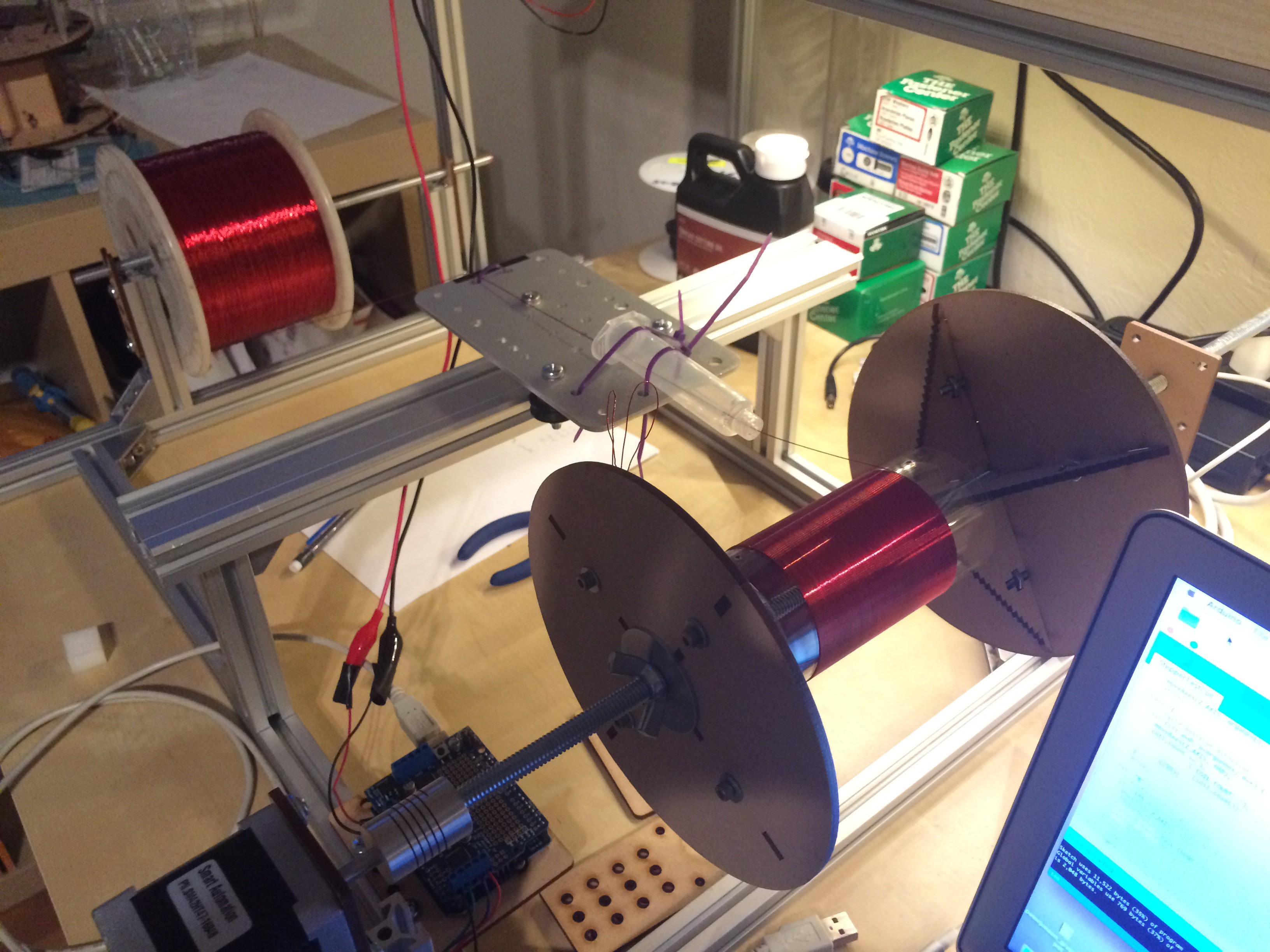
Being somewhat at the mercy of inspiration, a seemingly simple design suddenly came to me, and after a quick trip to the hardware store for some threaded rod, and by the end of the evening I had cobbled together some leftover Makerslide and Misumi aluminum extrusion into this:
The above half-complete winder allowed was just enough to wind a single-layer coil hundreds of times faster than I'd done it by hand (and nearly perfectly), convincing me that I was onto something.
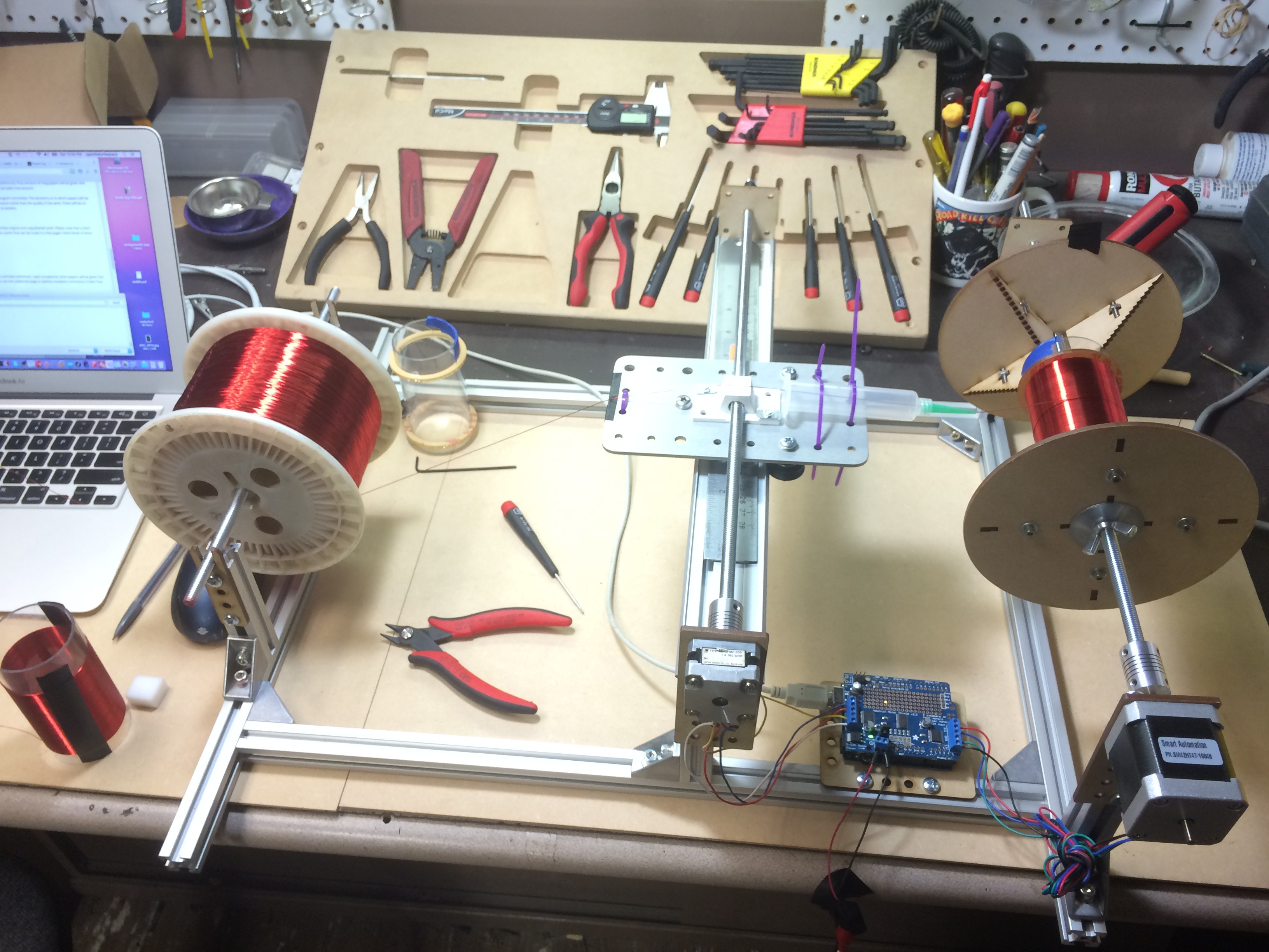
After another evening slaving over a warm laser cutter, the coil winder emerged:
The different components, drawn from leftover pieces of projects, are the following:
Rotational/Winding Stage (right side):
- NEMA17 Stepper with plenty of torque to draw the wire from the spool (from Inventables, I believe)
- Coil Wedges: Two laser-cut wedges that are tightened around the coil form to hold it in place. I cut these to look like step drills, so the coil would be positioned relatively straight, and there'd be at least a millimeter or two of area to bite onto.
- 5/16 threaded rod, M8 coupler, and large washers/wingnuts (hardware store/ebay)
- Laser cut NEMA17/threaded rod holder that mounts to the aluminum extrusion.
Linear Stage (middle):
- Makerslide linear rail and carriage (from Inventables)
- Plastic syringe and tips intended for solder paste (from Zeph Paste), zip-tied onto the carriage
- 5/16 threaded rod, NEMA14 motor, M8 coupler
- 3D printed carriage/nut holder from the OpenCT2 project
- Laser cut NEMA1/threaded rod holde
Spool Holder (left):
- Heavy wire spool (for tension)
- 5/16 rod, two laser cut holders.
Control:
- Arduino Uno with Motor Shield
- Modified OpenCT2 motion control firmware, with added commands on the serial console for coil winding and keeping track of the number of winds!
The dimensions of the long aluminum extrusion pieces are about 50cm, and the short ones holding each component are about 10-12cm high. The aluminum extrusion makes it easy to resize for larger/small coils, and to move in the tip of the liner stage very close to the coil form during setup.
Winding Coils
Following Bradley Worley's great proton procession magnetometer (PyPPM) project, I decided a good place to start would be replicating his (or a similar) proton procession magnetometer, then experimenting with it under different non-uniform field conditions to see how viable the coded field technique may be. About 10 years ago Stefan and Richard Hollos published a book called Signals from the Subatomic World that also describes building a proton procession magnetometer. Both serve as good introductions and have conceptually similar hardware (even if the specifics are different).
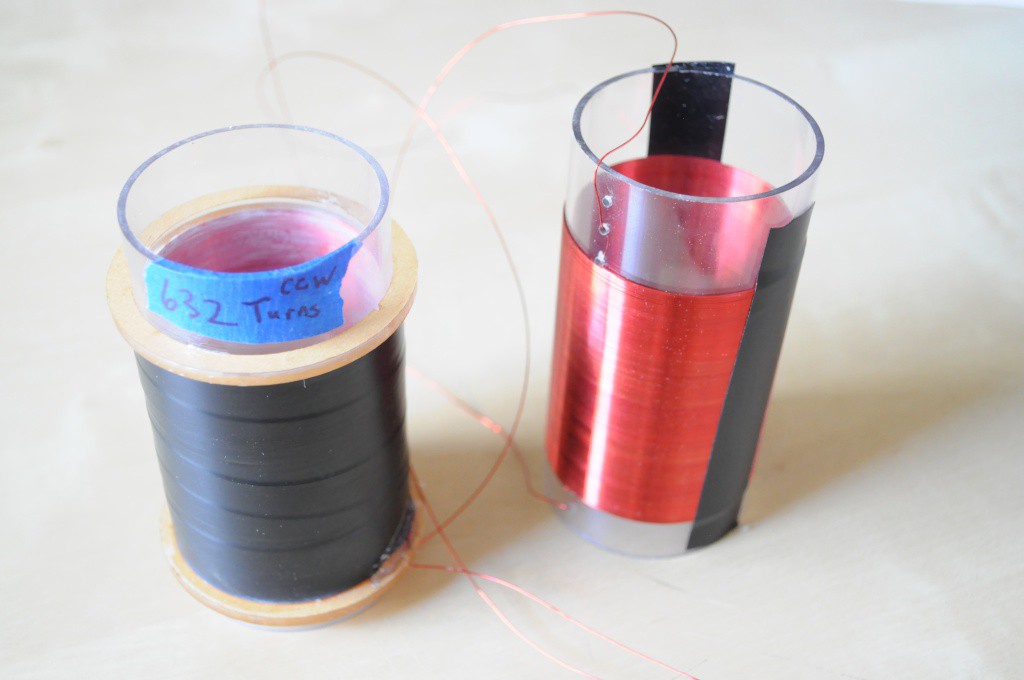
Bradley had success with his version 1 coil, which is a single coil containing 4 layers of 158 turns each (632 turns total). I decided this was a good coil to start with (since I've never successfully wound a coil before), and then I'd work towards winding more sophisticated coils. Bradley specifies using a version 2 "humbucker" coil (two identical but counterwound coils) to cancel out much of the 60Hz environmental noise, which is easily visible on his great first raw plots. The Hollas PPM sensor coilalso uses a humbucker arrangement, with similar specifications to Bradley's single coil (4 layers @ 138 turns/layer). The raw data in Chapter 7 of their book looks substantially noisier than Bradley's, but they were doing this a long while ago, and it's not clear whether they were subtracting baseline measurements, which should clean up the data a great deal.
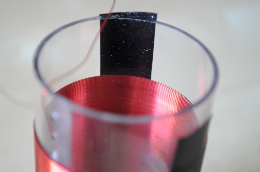
My first multilayer coil (the 4 layer, 158 turn/layer, 638 turns total) turned out much better than I was expecting. The current coil winder doesn't include anything to smooth out the very occasional tiny bump or bend in the wire, so some layers have one or two more winds than others, but the overall packing density was very good, and the coil has a total of 638 counterclockwise winds. Another coil counterwound (to make the humbucker arrangement) will make for a good first set of coils for initial tests, I hope.
To keep the coil windings in place, I used some super glue, then covered the coil in electrical tape -- but next time I'd like to try something better. The superglue didn't bond well to the wire, and the electrical tape obscures observing the beautiful windings!
Analog to Digital Converter
An Earth's field proton procession magnetometer nominally weakly oscillates at 2khz, making an ADC with a sampling frequency above 20Khz adequite. The Hollas PPM uses a 12-bit ADC, where Bradley's uses a 16-bit ADC. Here, because we're interested in trying to spatially resolve the signal using potentially a wide range of frequencies, the requirements are higher. The Nyquist rate for resolving protons in a 1 milliTesla field, which is only about 20 times as large as the Earth's field, is about 84kHz. A 1 megasample/second ADC would give a Nyquist rate equivalent to about a 10 milliTesla field, which seems like it would give some room for experimentation. Intuitively I have no sense of how much frequency range will be required, with it likely relating to a bunch of factors, and so it will likely be best determined empirically through some experimentation.
It's been oddly difficult to find an analog to digital converter that has the following specifications:
- 1 megasample per second or greater (but 100kSps would be okay to start, too)
- 14 to 16-bit resolution
- Ability to record several seconds of data
- Ability to stream the data through an easy-to-use API
I have investigated the specifications for every USB digital storage oscilloscope or DAC that I could find, and while many have substantially higher sample frequencies or sufficient resolution, most attractive solutions (like the Analog Discovery Kit) appear to have not been designed to acquire data for long, and suffer from an extremely low sample memory.
I don't have a great solution for this, but I've thought about starting with a USB soundcard capable of sampling at 16-bit/192Ksps to begin. I've also picked up anArty FPGA board to tinker with, which includes a fast ADC and a large amount of memory that could be used to store samples -- but creating a high-resolution long-memory FPGA oscilloscope would be quite an undertaking, and I'd rather make my mistakes cheaply and find an off-the-shelf solution. Suggestions are welcome!
As always, thanks for reading!
 peter jansen
Discussions
Become a Hackaday.io Member
Create an account to leave a comment. Already have an account? Log In.