 engunneer
(August 2015)
I did the PCB design as a way to evaluate CircuitMaker. I already use Altium Designer at work (occasionally), and I got into the Circuitmaker Beta and wanted to try it out. The basic LED/sensor cell is fairly straightforward. A WS2812B, a Cap for decoupling, and a LED/Phototransistor pair with supporting resistors.
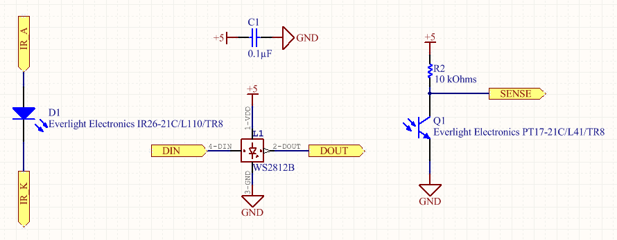
The IR LEDs will be chained together to reduce the number of resistors and the power loss.
The Sense lines run to a bank of shift registers:
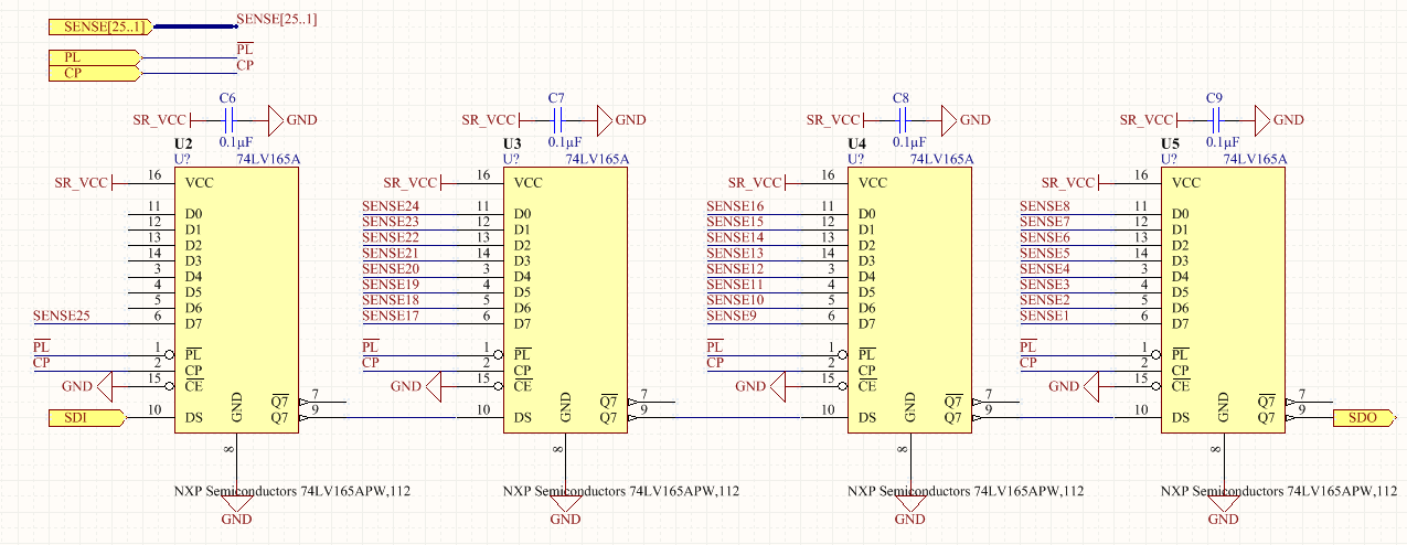
Unfortunately, with 25 sense lines, I needed 32 bits of shift register. Using shorter registers (but more of them) would have been more expensive.
Lastly, the power supplies to adjust both the IR LED power, and the VCC (and therefore threshold voltages) of the shift registers.

It turns out I got the power supply resister values wrong because I used the wrong formula from the datasheet, but that's easily fixed later.
Once I had the basic layout of the cells on the top and the shift registers on the back, I started the routing, which I also timelapsed. Here's the last 4 hours of routing in under 2 minutes:
Discussions
Become a Hackaday.io Member
Create an account to leave a comment. Already have an account? Log In.