The new brackets are printed and work fine for keeping the board centered in the frame.
I failed to mention in the last post that one of the reasons I made the brackets was that the assembly got damaged, and all the connections between the boards saw heavy stresses. Quite a few pads got ripped off of the edges of the boards.

I hit each joint with the soldering iron to figure out what pads were gone, and then scraped the solder mask off each bad ground joint to make a new connection. The power connections have vias nearby, so I could use a short piece of resistor leg to make the jump. There is some redundancy due to the grid layout, but I still don't want too many joints to go bad. The brackets keep all the relative motion out of the assembly.
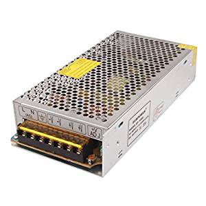
I also took a moment to re-evaluate the power requirements. I had originally planned for each board to be 9x9 LEDs, so a total string of 729 LEDs. At ~60mA each at full brightness, we were talking about over 40 Amps at full brightness! I decided that the we'd just not be able to run them at full power and bought a 5V 20A supply, which is still huge.

I needed to fill an item for free shipping on Amazon this week so took some time to recalculate the power supply needs.
Adafruit estimates 20mA per LED for normal use, which is about 4.5 Amps for my display. The WS2812 LEDs are by far the largest current consumer, but the IR LEDs take probably 50 or so mA more per board. I also measured the current with all LEDs at full brightness as just a hair over 2A. That means each LED is only drawing 8mA, which seems a little light.
In any case, I found a 5V 4A supply so I still have plenty of headroom, and it is a simple wall wart, so looks much better than the industrial supply. Mine does not have a power LED as shown in this image.
 (Image from ebay)
I also upgraded the board to use a barrel jack that I can mount to the frame.
 engunneer
Discussions
Become a Hackaday.io Member
Create an account to leave a comment. Already have an account? Log In.