 Christoph
Well the board was delayed a bit in customs, and then by me because I had more important things to do, unfortunately.
Top:
 There are a few familiar headers I'd like to start with:
- At the top left corner there's the Pi's GPIO header,
- then, along the top edge, one row of arduino headers
- the second row of arduino headers is at the bottom edge
- and finally the two rows or Teensy 3 headers.
Additionally, the board comes with
- the yellow header (YH1, top right) for jumpers that connect between the Teensy UART1 and the RPi's UART (pins 8 and 10 of the Pi's GPIO)
- H2, which has the Teensy's SPI pins (11, 12 and 13), Reset, and power,
- and H3 for jumpers that connect either the Pi or the Teensy to the I²C signals on the arduino headers.
There's also a pogo pin that is supposed to hit the Teensy's reset signal at a test point that is located on the bottom side of the Teensy. I don't really believe that as I've already touched it and it looks a bit slanted.
Also, no silk screen hint about which way the teensy goes in, I had to grab the schematic to find out. And I measured the supply pin voltages to be sure.
Bottom:
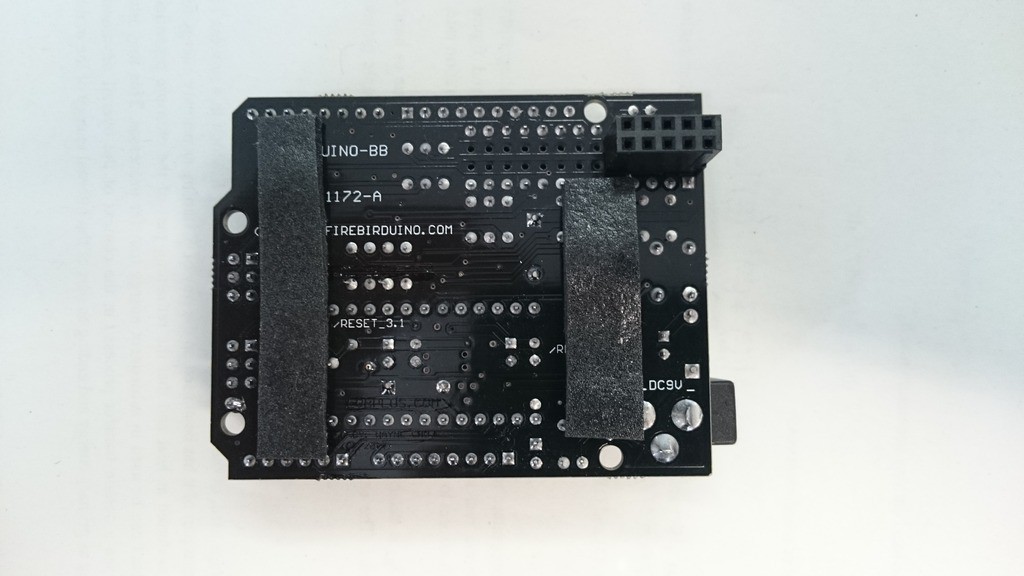
How nice! Foam strips to protect the display and camera connectors! Not much more to say about the bottom side (for now).
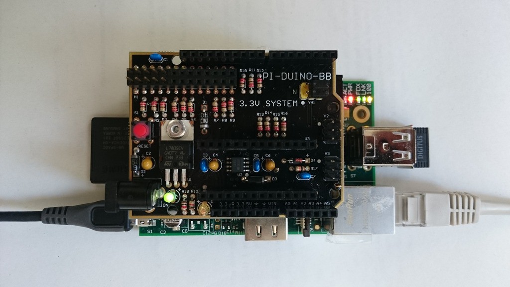
Stacked with the Pi:

The board overlaps the LAN and video jacks. That's not a problem right away, but let's take a closer look:
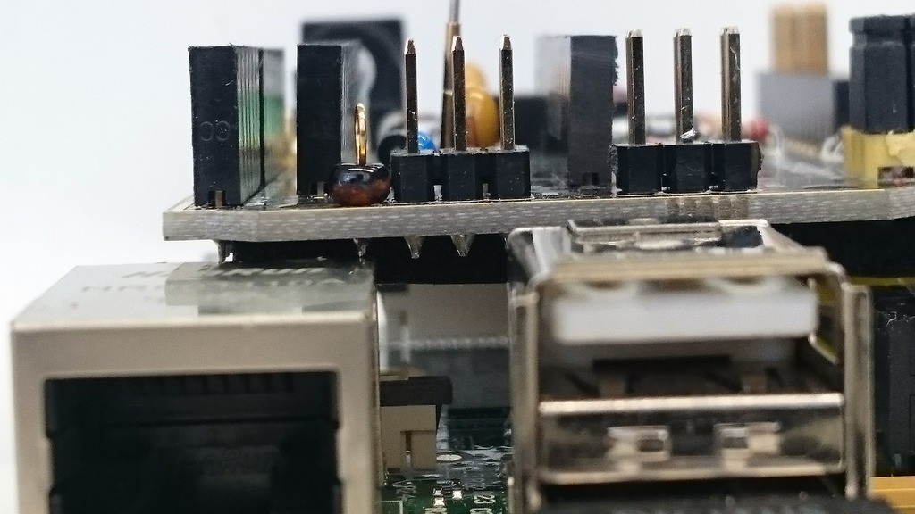
Yup, the pin touches the jack. I don't know what the "bead"-thingy is, but this will surely benefit from a piece of tape. The same for the video jack:

with tape already applied. After that was done I powered the combo up and there was no smoke:
I'll plug in a Teensy next time and try to talk to it via serial (PC -> Pi -> Teensy (echo sketch) -> Pi -> PC).
Discussions
Become a Hackaday.io Member
Create an account to leave a comment. Already have an account? Log In.