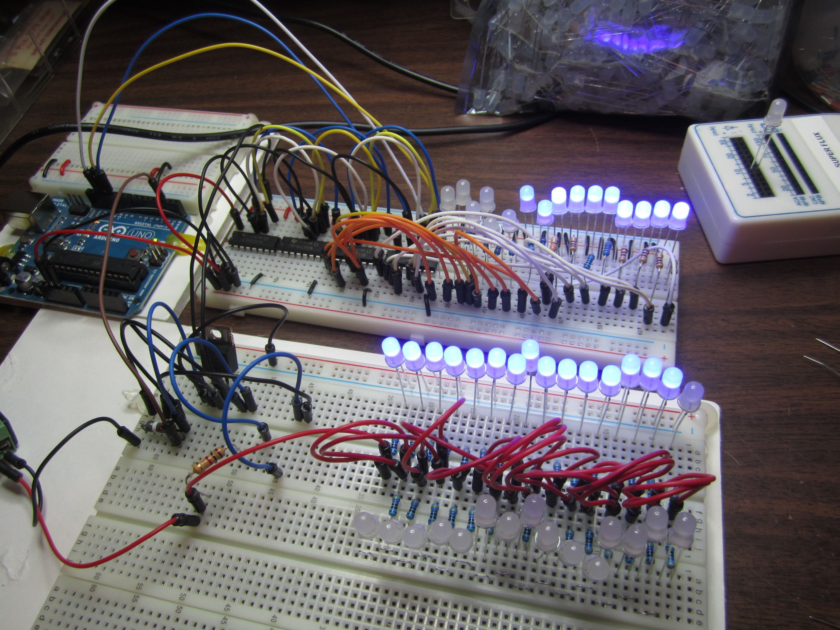
Before soldering the cube, I want to make sure that it will work as expected, so I wired up as much as I can on a breadboard to do a practice run:
In the foreground breadboard I'm testing the different transistors to drive the cathode of all 64 LEDs that's on a layer. I only wired up 32 to get an idea of current that the transistor has to deal with. I tested three different transistors to drive the LED cathodes and liked the MOSFET the best.
In the background breadboard I'm testing the shift registers. I only have four shift-registers on hand, so that's what I wired up.
Although the LEDs look very bright in the photo below. In real life they're not that brightly lit. They're dim because we'll have eight layers with unique cathodes, but all the layers share the same 64 anodes. So each layer is only lit 1/8th of the time. I've lowered the LED resistors down to 100 ohm, I don't dare go lower in case they're ever lit without any pulsing.
My multimeter shows that each LED is only consuming 2mA. I think its confused by the pulsing.

 Hari Wiguna
Discussions
Become a Hackaday.io Member
Create an account to leave a comment. Already have an account? Log In.