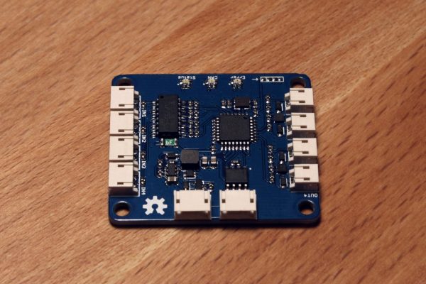
RelayDrive is a HydroBot module designed to drive relays and other electro-mechanical devices. It consists of 4 low-side outputs, each rated for 1A continuous current, as well as 4 digital inputs, and is controlled over CAN. This module is intended to drive mechanical relays, solid state relays, and solenoids for controlling devices such as lights, pumps, heaters, fans, and valves in a HydroBot hydroponic system.
RelayDrive Features:
- STM32F0 microcontroller
- 4 low-side 1A outputs
- 4 opto-isolated digital inputs
- 3 LEDs to indicate device status
- 6-30V input works with 12V and 24V systems
- JST-ZH series connectors
- Parallel bus connections for daisy-chaining
- Protofusion pogo programming interface
- Open source design
Each of the outputs of the RelayDrive module can be controlled as discrete on/off switches, or can be configured as PWM outputs. Each of the inputs can also be independently configured as digital inputs or frequency inputs. Frequency inputs are measured in Hz and can currently read input signals up to 1KHz. The default firmware uses a CAN baud rate of 500K. It sends out status messages on ID 0x204, with digital or frequency input readings, and receives command messages on 0x203 to control outputs and set input and output configuration.

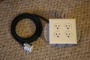
Because many devices in a hydroponic system run on mains power and require relays for control, I packaged up 4 solid state relays in a 2 gang electrical box. This keeps all the relays together without exposing any hot wires, and the 4 controlled outlets match up nicely with a single RelayDrive module.
All source can be found in the HydroBot repository, including firmware source code and hardware files. The BOM and generated gerber files are also included for easy replication.
 matthewreed
Discussions
Become a Hackaday.io Member
Create an account to leave a comment. Already have an account? Log In.