 Jithin
A breakdown of the schematics : Full schematic is part of the design package in github.
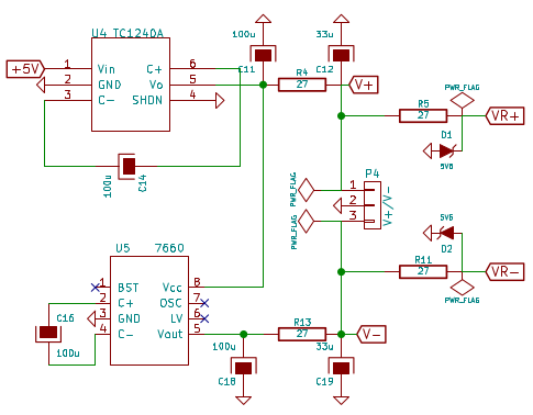
Figure : Bipolar power supply generation using charge pumps
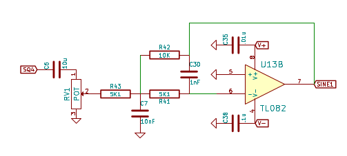
Multiple feedback filter for sine wave generation.
The values were simulated using a calculator hosted by OKAWA electric design
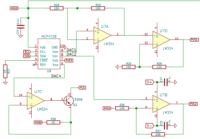
Using a 4-channel DAC to drive three voltage sources, and a current source. This model has high error margins, but since these are always consistent with the reference voltage, a point by point calibration(4KB per channel) can be used to achieve the maximum resolution of 12-bits.
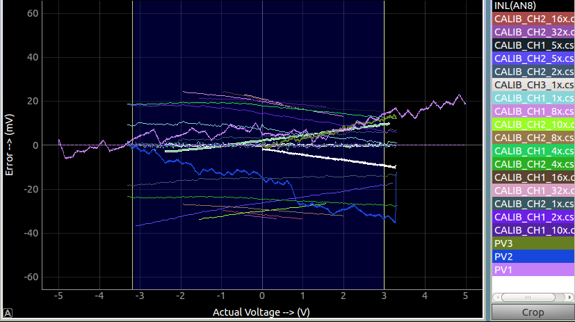
Figure : Calibrating the analog channels against a calibrated 24-bit ADC.
The jagged lines belong to the DAC channels. As is evident from the graph, these cannot be fitted against polynomials of a few orders, so I went ahead and stored the errors on a per point basis (with two more constants for autoscaling the errors to a 1 byte full range).
Discussions
Become a Hackaday.io Member
Create an account to leave a comment. Already have an account? Log In.