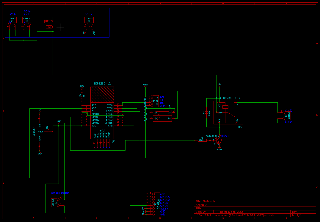
The updated schematic for the MK0.2 is ready! I have offloaded the PSU to a 3rd party board, and I have switched out a few parts that weren't up to scratch.

- I have changed the transistor to one that will be able to cope in any scenario that should be presented to it
- I broke the spare IO into a proper header which also supplies V, 3.3V and ground enabling people to add their own input/output to it if they are so inclined (maybe even some add on boards!)
- 3.3V regulator - for, you know, regulated voltage
- DIP switches for ground and 3.3V for reset/programming of the ESP8266-12
- Pin 1 (RST) is NOT a DIP switch (this is a note, not an updated feature)
Still, no suggestions as for a nickname for this version - in case you missed it suggestions are welcome!
I have now moved onto designing the PCB, i'll let you know when i'm done!
Discussions
Become a Hackaday.io Member
Create an account to leave a comment. Already have an account? Log In.