For now...
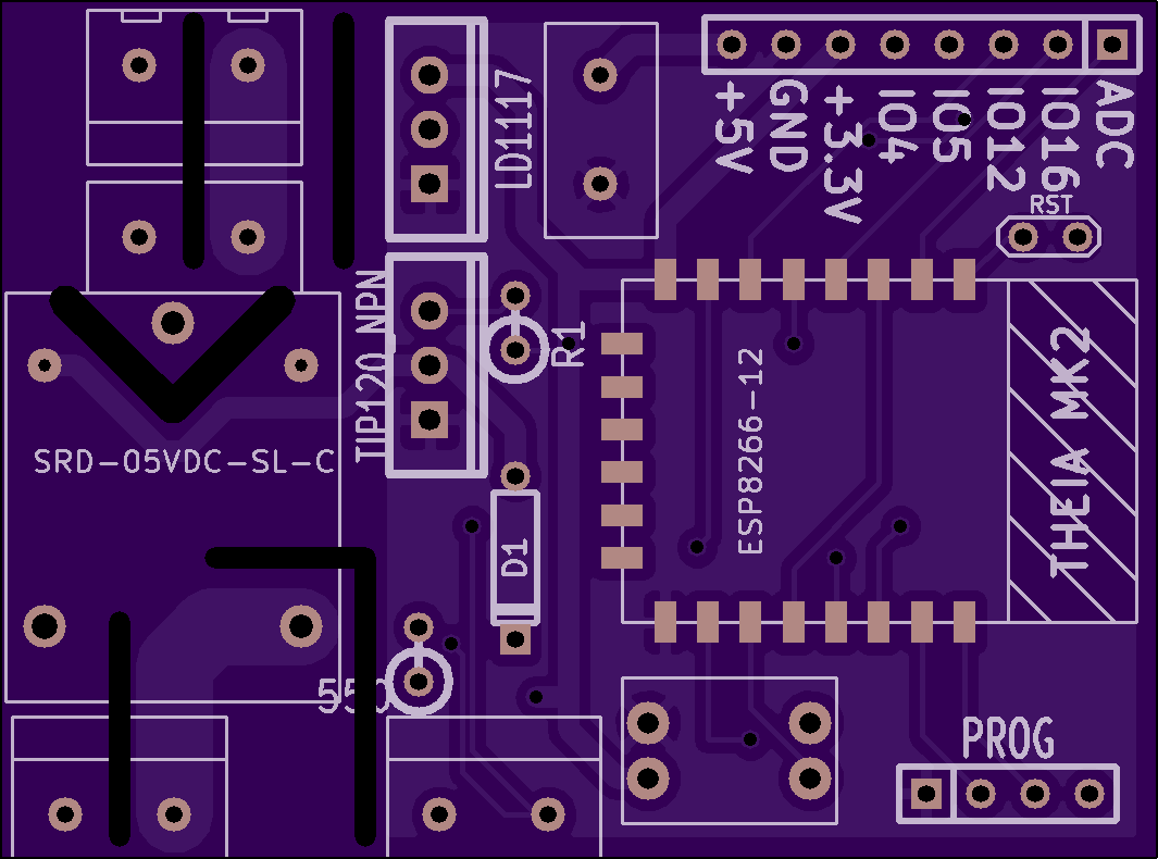
- It has GPIO in the top right, with both 3.3V and 5V@1A available, as well as access to the ADC and 4 separate IO's to allow people to add their own sensors (or maybe even some add-on boards)
- There's a programming port in the bottom right (links directly to RX, TX GND and 3.3V)
- There is also a DIP switch in the bottom right to put it into programming mode (it's a dual DIP switch, one for ground, one for 3.3V)
- A reset tied to ground in the top right corner, you can use a pair of forceps/tweasers for this.
- The mighty ESP8266-12 ( or ESP8266-12e) at the heart of the board
- The SRD-05VDC-SL-C relay on the left of the board, for handling the switching (this will be a latching relay in future revisions for power efficiency, but it's not so important considering this is only a prototype)
- Now with some degree of shoddy isolation!
Front:

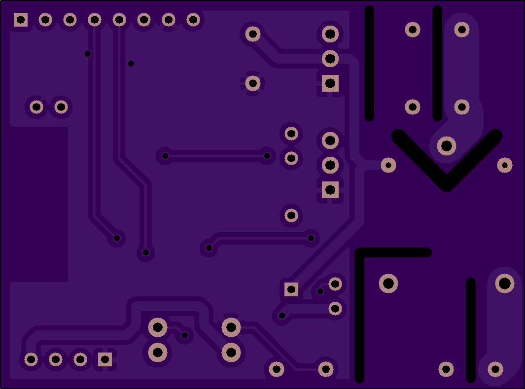
Back:

Update:
Prototype board is now ordered, should be arriving soon!
Discussions
Become a Hackaday.io Member
Create an account to leave a comment. Already have an account? Log In.