-
Design Finished!
08/15/2016 at 19:02 • 0 commentsThe design for the first prototype (nicknamed WEISS) is finally done, I've been working on this almost everyday for the last week or so, I'm still getting my way around the KiCad environment.
Be warned though, this design is by no means safe, and may not even work - this is the largest collection of electrical components I have ever conceived, and I'm no electrical engineer.
So be advised, this design has the potential to hurt you, blow out your fuses, or worse.
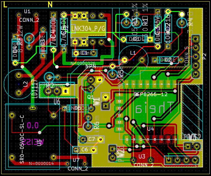
So without any further ado, some images;
![]()
It occupies the space of 60x50 mm, so it can just about fit in a UK back plate (only one of the deep ones though because of the height of the relay).
![]()
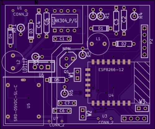
Top. It appears that OSH Park cannot cut oval though holes, oh well, I'm sure I can fix that with a dremmel or something.
![]()
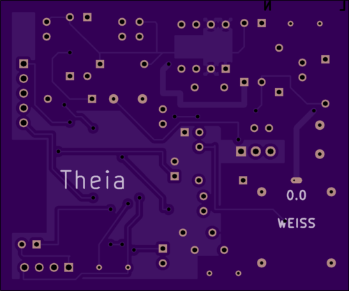
Bottom. I accidentally marked it as 0.0 instead of 0.1, nevermind.
I haven't ordered the board yet, but intend to do so soon as well as ordering in the parts so that I can see whether my shoddy (at best) PCB design skills came through in the end. That's all for this update, see you!
-
Features
07/31/2016 at 11:25 • 0 commentsI have begun designing the schematics of the first prototype. There are many features that I would like this device to accomplish, but some of them will not be feasible, and many of them will not be included into this first prototype because it needs to initially be simple so that if there are problems, they can easily be ironed out. More complicated features will be trialled out in later prototypes. It occurs to me that I should probably be saying what these features I would like to implement are, so I am going to put a list below this paragraph, but also put a list I will keep up-to date on GitHub here. I would very much appreciate if people interested could suggest on features to add, after all this is a device for people like you reading this, so I would like it to be as tailored and equipped as possible towards your needs whilst still remaining relatively low in cost - you want power usage monitoring? Suggest it as a feature. Maybe if there are enough suggestions we can hold a poll to see which ones should be included in the next revision.
Suggestions:
- Clap detection circuit
- Current flow detection (detect if the bulb is on or not, switch state, blown bulb, etc.)
On another note, I am developing this project under Creative Commons 4.0 SA license, which you can read here. So, if you want to take the designs posted here and use them, commercially or otherwise - go ahead, providing that you give credit and also share your designs under the same licence.
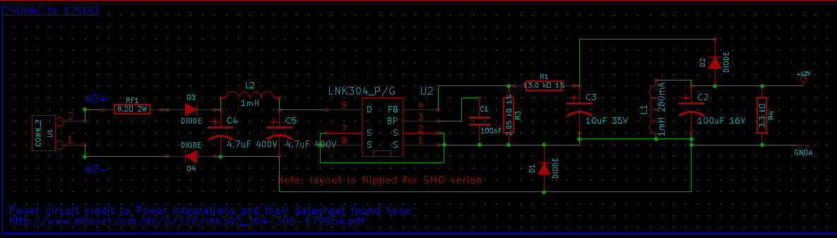
I have also finished rebuilding the power circuit from the datasheet on the LNK304 from here, into Kicad. This is how I intend to power the device from the lighting mains circuit.
![]()
Also, for anyone interested, I am using Kicad primarily because it works on the Raspberry Pi - I make most of my update on a computer, but most of the schematics are made on my Pi because no-one else needs to use it so I can take my time. This also means that I have to use an obsolete version of Kicad, but luckily the newer versions are backwards compatible regarding files, so I still intend to share those.
That's about it for this update, I hope to see some suggestions!
-
Power
07/17/2016 at 18:48 • 0 commentsOkay, so this device will need power. I considered running it on batteries, but it would complicate debugging wireless and other such issues, and if its going to derive its power for switching the relay it may as well also power the logic.
This device will have to turn ~240VAC into 12/18VDC and 3.3VDC, I was looking at some parts on digikey, but the cost is prohibitive on some of them, more so on the ones with dual output: [LINK]
I have however discovered some devices on Mouser that will covert 240VAC to 5VDC, they are relatively cheap, but most importantly they are safe and take up minimal space. Far safer and space efficient than if I were to attempt building my own power converter onto the board.
![http://www.mouser.co.uk/images/powerintegrations/images/dip8c.jpg]()
I'll do some more research but hopefully this will allow the Theia to run straight of of the lighting circuit of the house without the need for batteries.
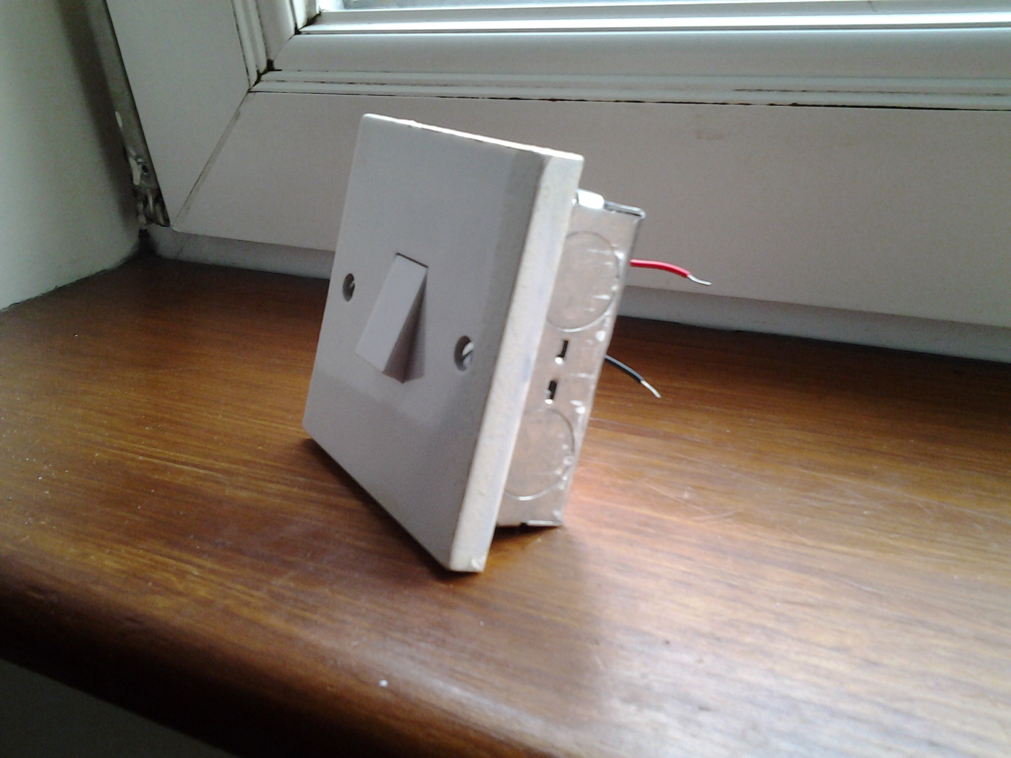
Incidentally, I have now created a test jig, which I will use to easily test any prototypes I create and as a basis of what kind of light-switches are compatible.
![]()
-
Preliminary Design Mechanics
07/14/2016 at 17:44 • 0 commentsI was asked a very pertinent question by [3dscuba].
how do you plan on having the manual switch and the IoT have the same priority? It seems like you either give the manual switch priority or the IoT switch priority?
I gave an answer to his question, but feared that it did not come across very clearly, so I have created some diagrams to help illustrate how I intend for the Theia device to work, I will warn you, they're pretty raw-looking diagrams, and MS paint is the only tool I had to hand at the time - sorry.
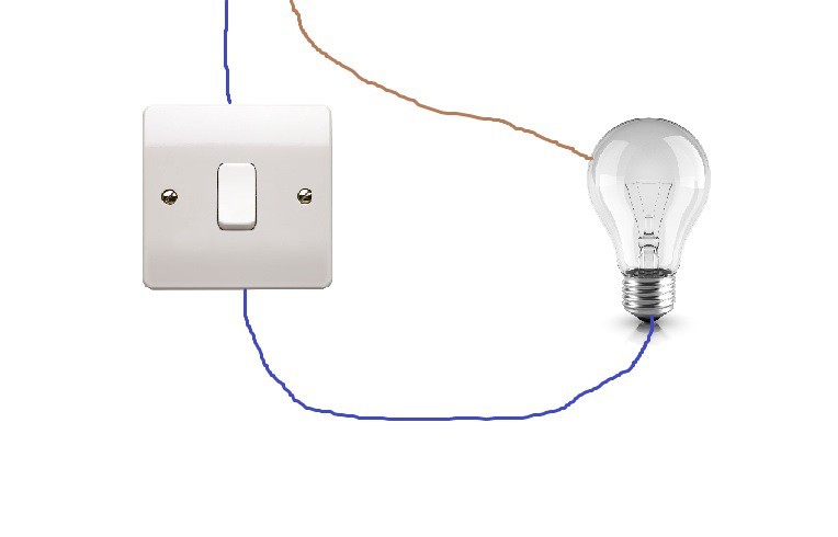
How an ordinary light-switch should work
![]()
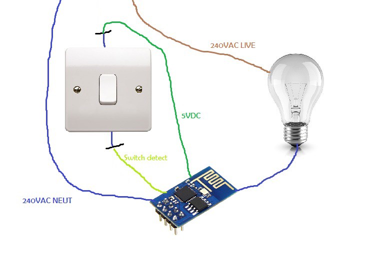
How the Theia device should work
![]() As you can see, the wall-switch is disconnected from mains voltage, adding an extra layer of safety in case someone like myself were to install it poorly. The switch is instead used by the Theia device (I used a picture of an ESP8266 because I had nothing else to use) as a physical interface. The Theia will detect a change in the switch (on/off) and will switch the relay on and off appropriately.
As you can see, the wall-switch is disconnected from mains voltage, adding an extra layer of safety in case someone like myself were to install it poorly. The switch is instead used by the Theia device (I used a picture of an ESP8266 because I had nothing else to use) as a physical interface. The Theia will detect a change in the switch (on/off) and will switch the relay on and off appropriately. When the IoT interface gets involved it will invert the state of the wall-switch, i.e. if it is off, the light will turn on, allowing for the wall switch to still be used to turn the light off. I believe that this system may be similar to how a two-way switch works, but correct me if I am wrong.
The mains voltage will be handled by the relay on the Theia which will be "Single Pole Double Throw" to emulate a real light-switch, meaning it can be immediately installed with next no modification to any of the other lighting circuits, meaning anyone can install it themselves at home (within reason).
The Theia will also have a way of detecting whether the light in question is on or not, but I'm still working on that, suggestions are welcomed and very much appreciated.
-
The Concept
07/12/2016 at 17:17 • 0 commentsSo, before I can begin designing this device, I must have a concept and some design criteria ready.
- It must not be over-ruled by the light-switch (i.e. most lighting hacks will only work whilst the light power switch is in the up position, I want this to work more like a 2-way switch)
- Integrate almost seamlessly with the switch face-plate so that a normal 2-way switch is still possible
- Have IoT functionality (i.e. can be controlled and automated using Node-RED)
- Can be used like a normal light switch (can be used as 2-way switch, etc.)
Like I mentioned above, once installed, it should interact (at least electrically and physically) like a normal light switch. Normal light switches are usually SPDT and as such have three contacts; Common, 1-way and 2-way. Forgive me and/or correct me if I'm getting any of this wrong as I have very limited experience with these things as I am not an electrical engineer by profession, merely a hobbyist.
Theia IoT light-switch
An easy, cheap and open source way to add IoT to a light switch.