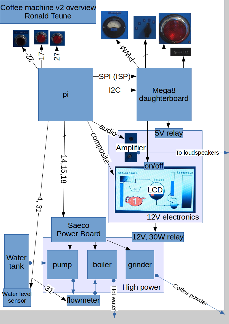
Block diagram
Numbers are Raspberry Pi GPIO numbers.
 Power module / grinder
To solve the problem in Coffee Machine v1 that after making coffee, the environment was covered in brown dust, I needed another grinder. A friend of mine gave me a Saeco Talea, completely functional except for the corroded boiler.
For the Saeco I found the most extensive Service Manual I ever found for a device. For example, on page 35, they describe their coffee autodose algorithm based on (1) grinder power consumption, (2) pulse (=rotation) count and (3) selected aroma. A wonderful piece of engineering. The quality of the power board, and these fine-tuning mechanisms, made the Senseo look like a toy...
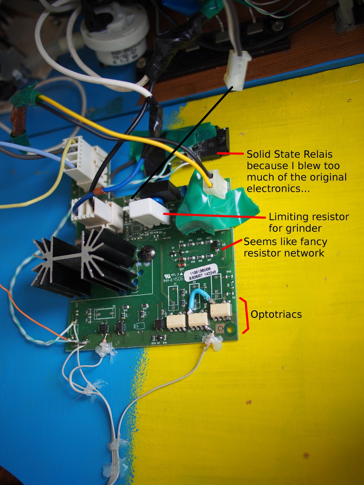
The power board for the Saeco looks really sturdy. I blew one or too optotriacs, but most of the circuitry I was able to reuse. The fancy resistor network is probably for measuring the power? But I don't use it (yet) since I can fine tune in code when needed. The big, heatsinked part is the final stage for the boiler. The lower power parts just have one simple optotriac stage.
For pump, boiler + heat sensor, water tank + level sensor reed relais, I used a Philips Senseo HD7800 with all the electronics removed. The boiler has a heat fuse switch next to the NTC, that's safe enough for me. No pictures of this part; many pictures are in the Repair Cafe Senseo Repair Manual made by hobbyists.
Audio
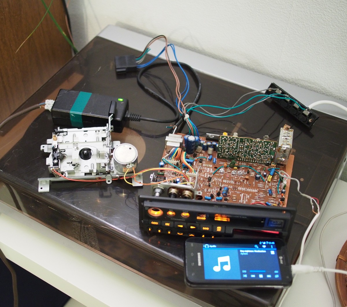
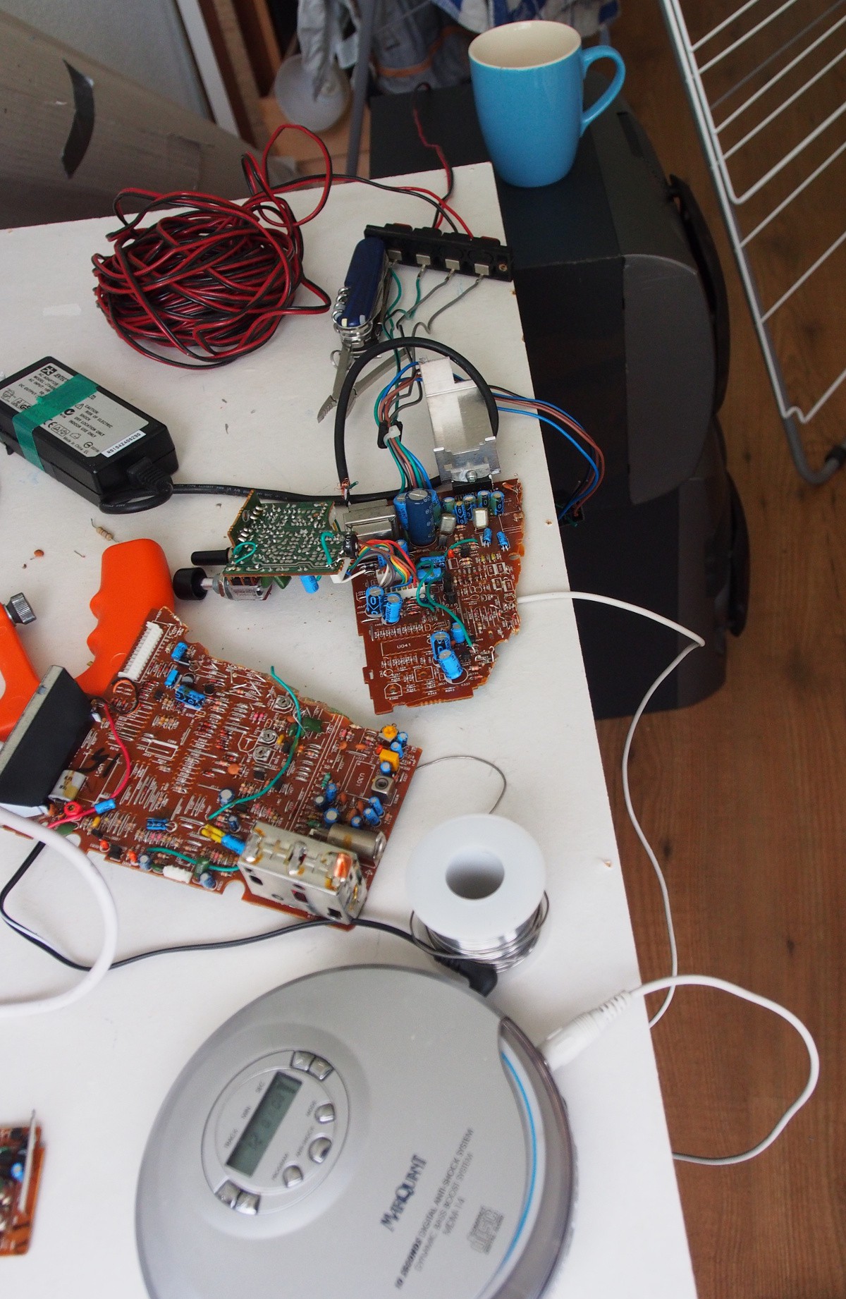
To remove the need for a separate audio system in the kitchen, I decided to build an amplifier inside the coffee machine. For this I used part of a car cassette system. Firstly I connected my phone to the cassette output, after that I traced the wires using the GIMP and semi-opaque layers of the front and the back of the PCB, to be able to cut off all but the essential parts.
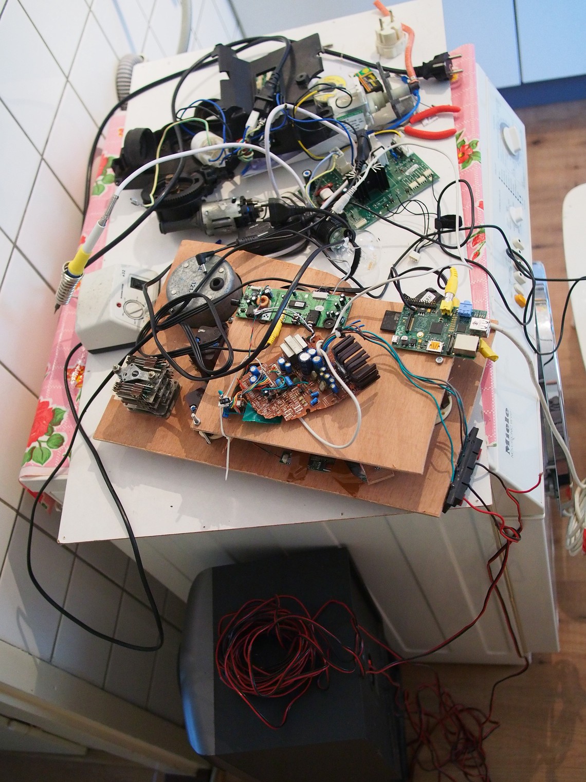
The internals
Work in progress... :) Testing the LCD, audio, power electronics.
Fully built:
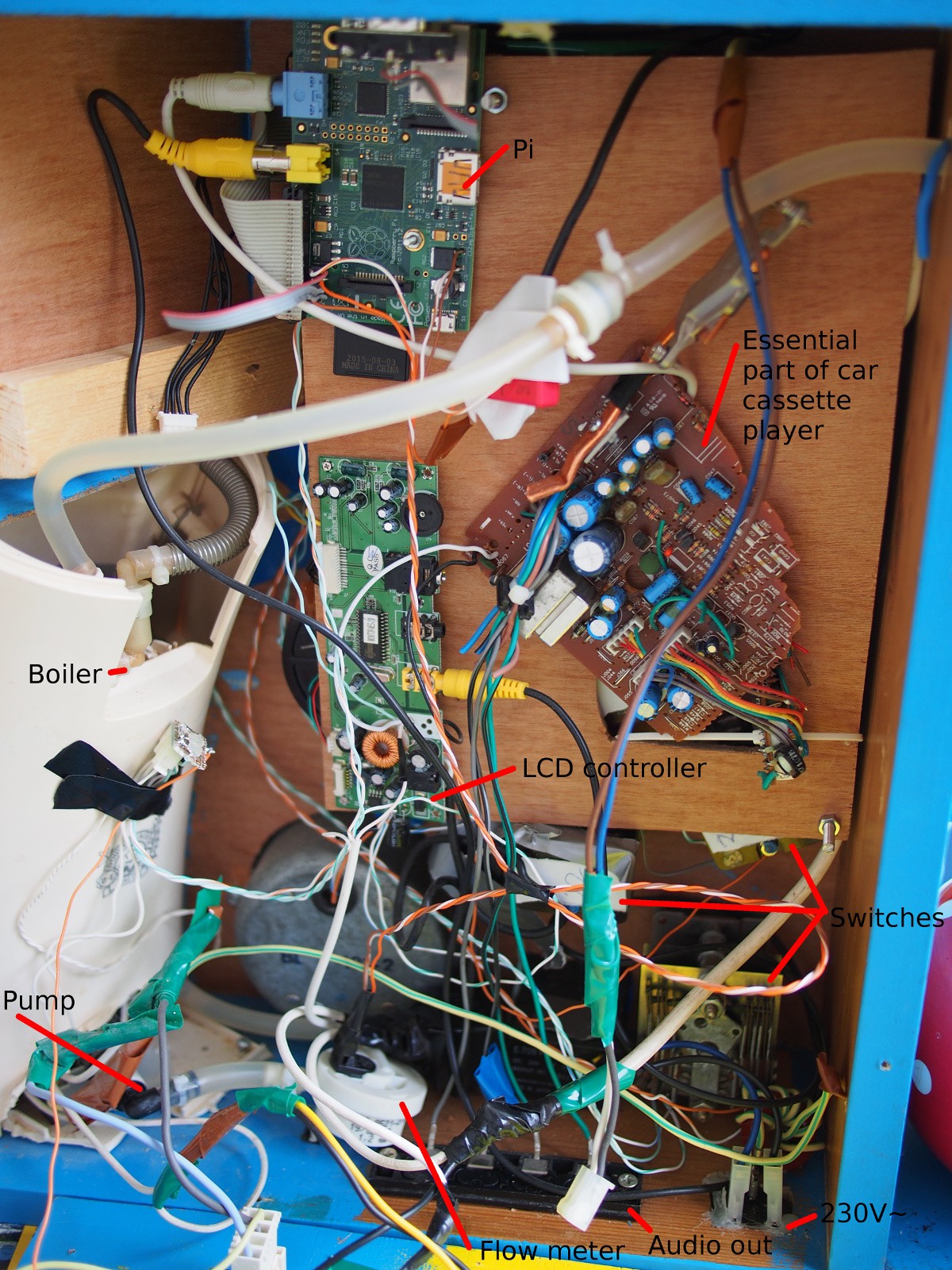
Both the flow meter and the grinder have a two little magnets inside, using a hall sensor to count the number of half rotations. The LCD controller + panel comes from a portable DVD player. Sadly only with 480x234 resolution...
Behind the wooden panel are the switches, and the RonaldBoard Mega8 daughter board. I forgot to take pictures of it, but it's not *that* exciting (and taking it apart again is quite some work...).
The 1-2-3-4-5 switch at the bottom right in this picture is actually a switch with 12 positions - of which only 5 distinct positions can be discerned after the years of usage before it ended up in a thrift store in Prague.
Discussions
Become a Hackaday.io Member
Create an account to leave a comment. Already have an account? Log In.