CCD Board Evolution
The picture below shows the evolution of the CCD controller board from perf board to etched PCB to OSH Park PCB.
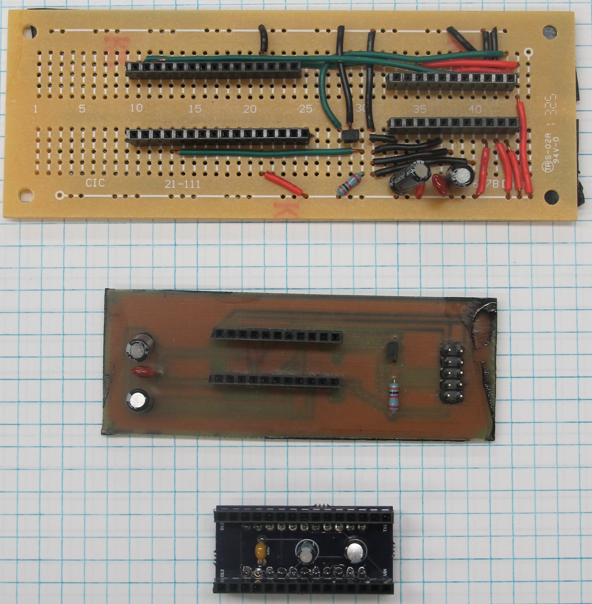
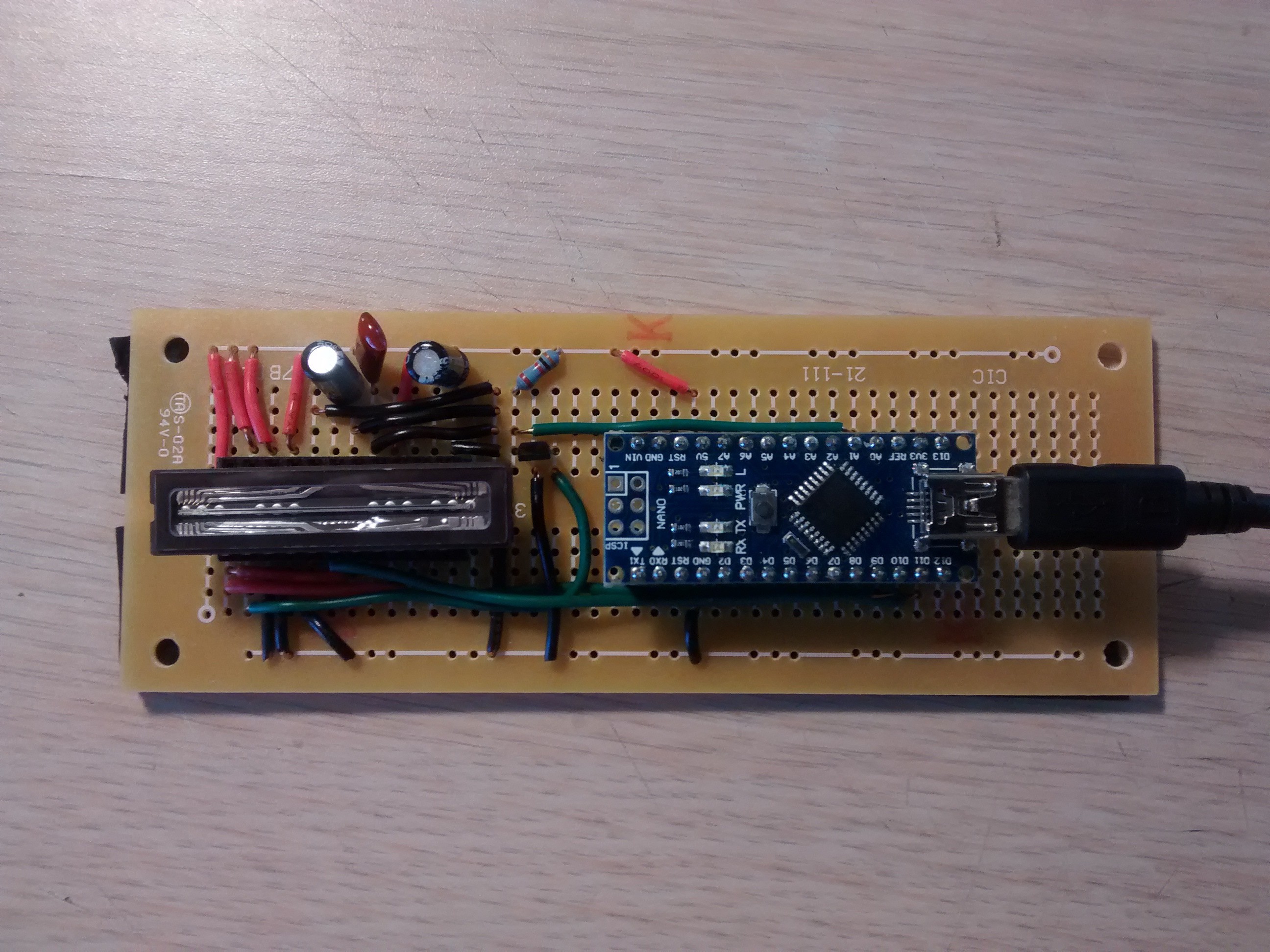
Perf Board
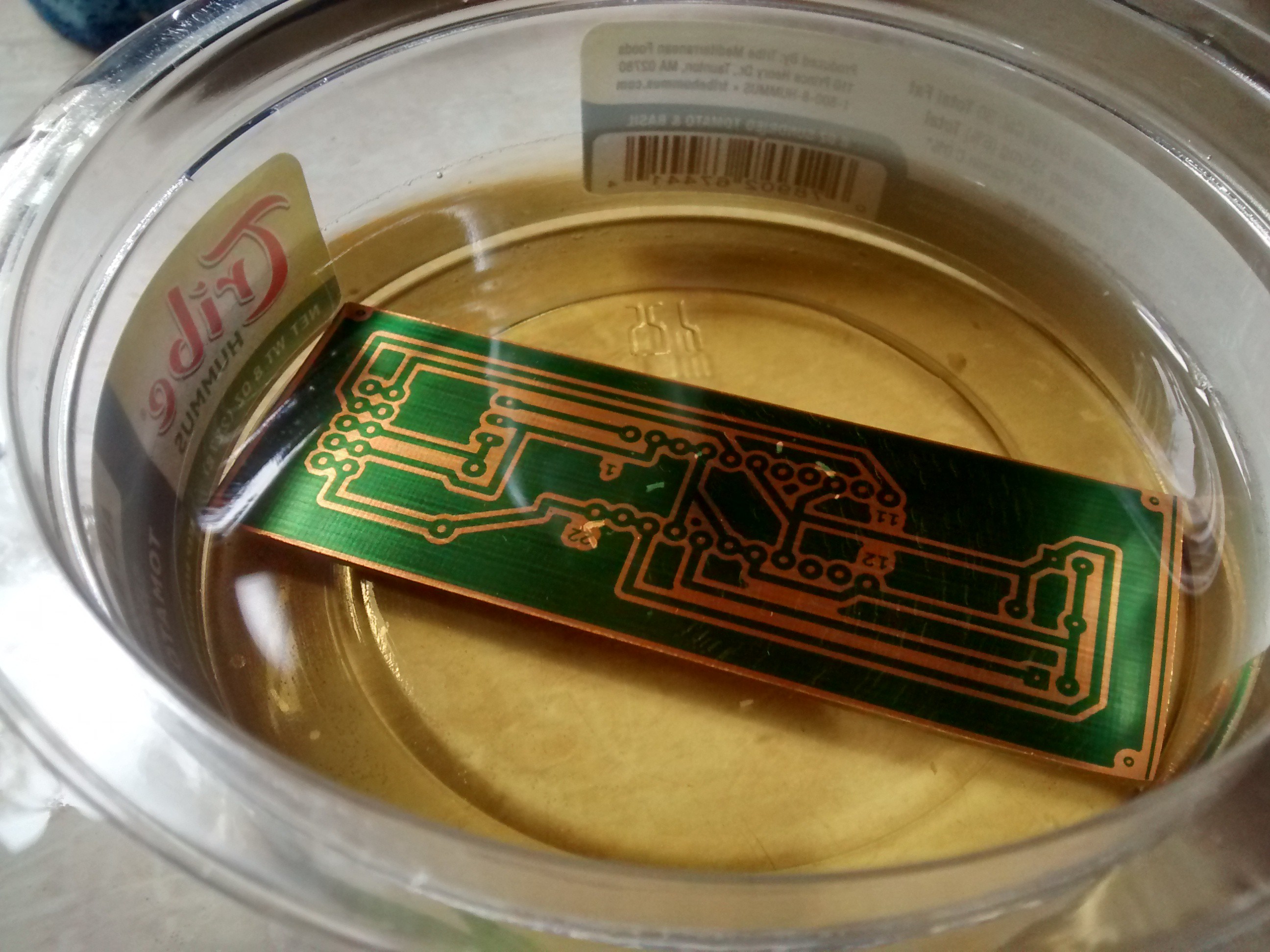
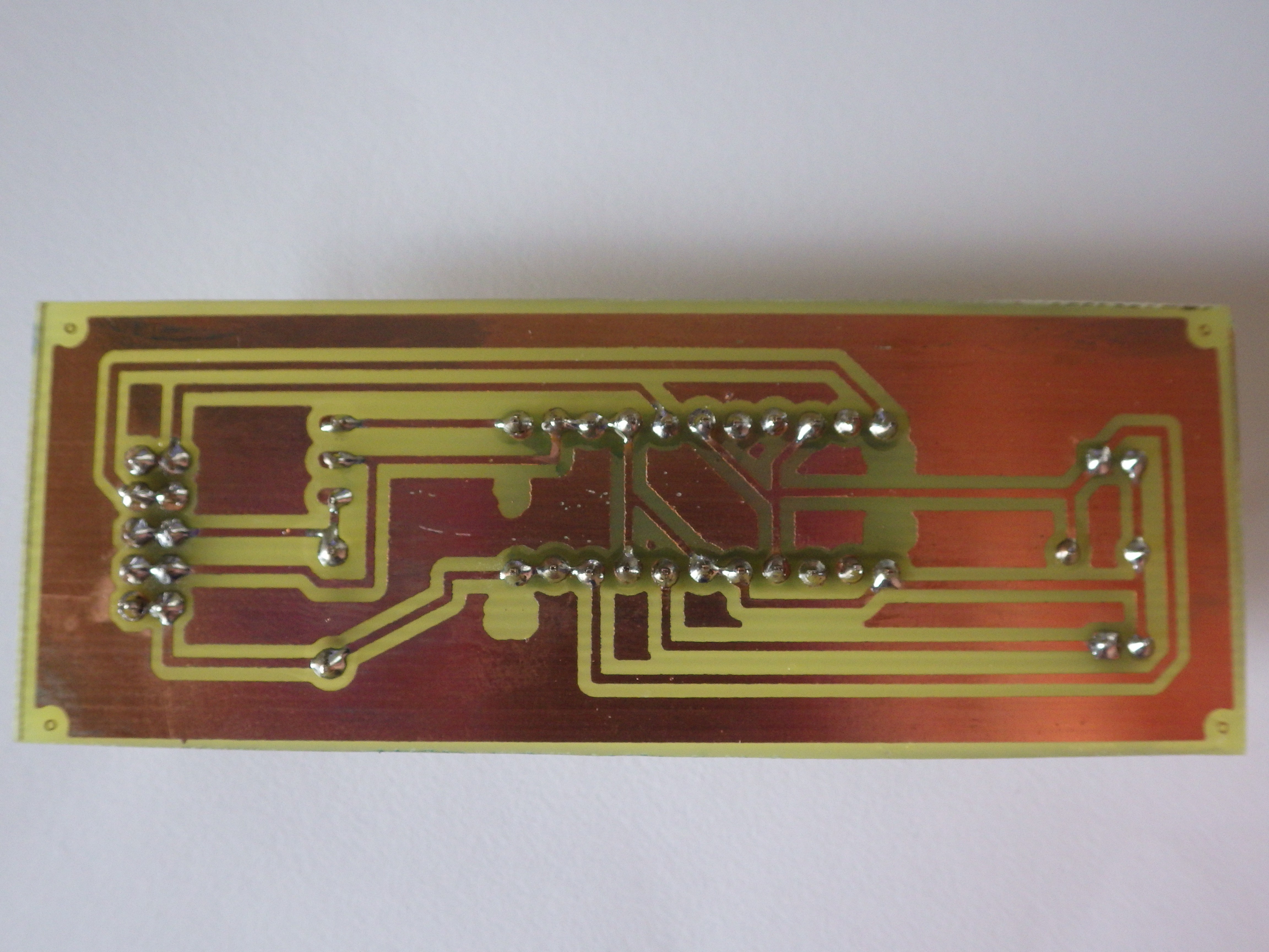
Etched PCB
Etching in progress..........
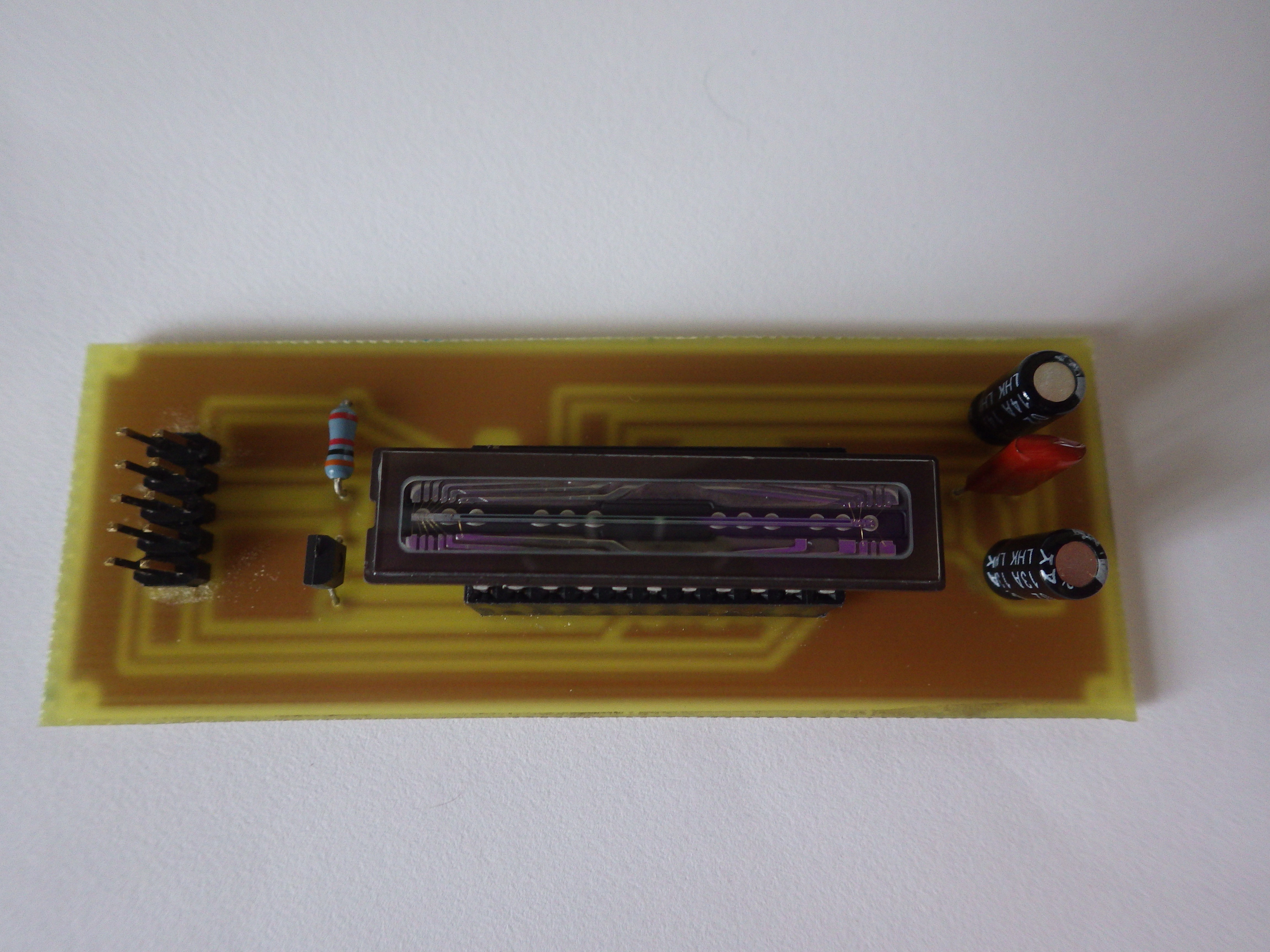
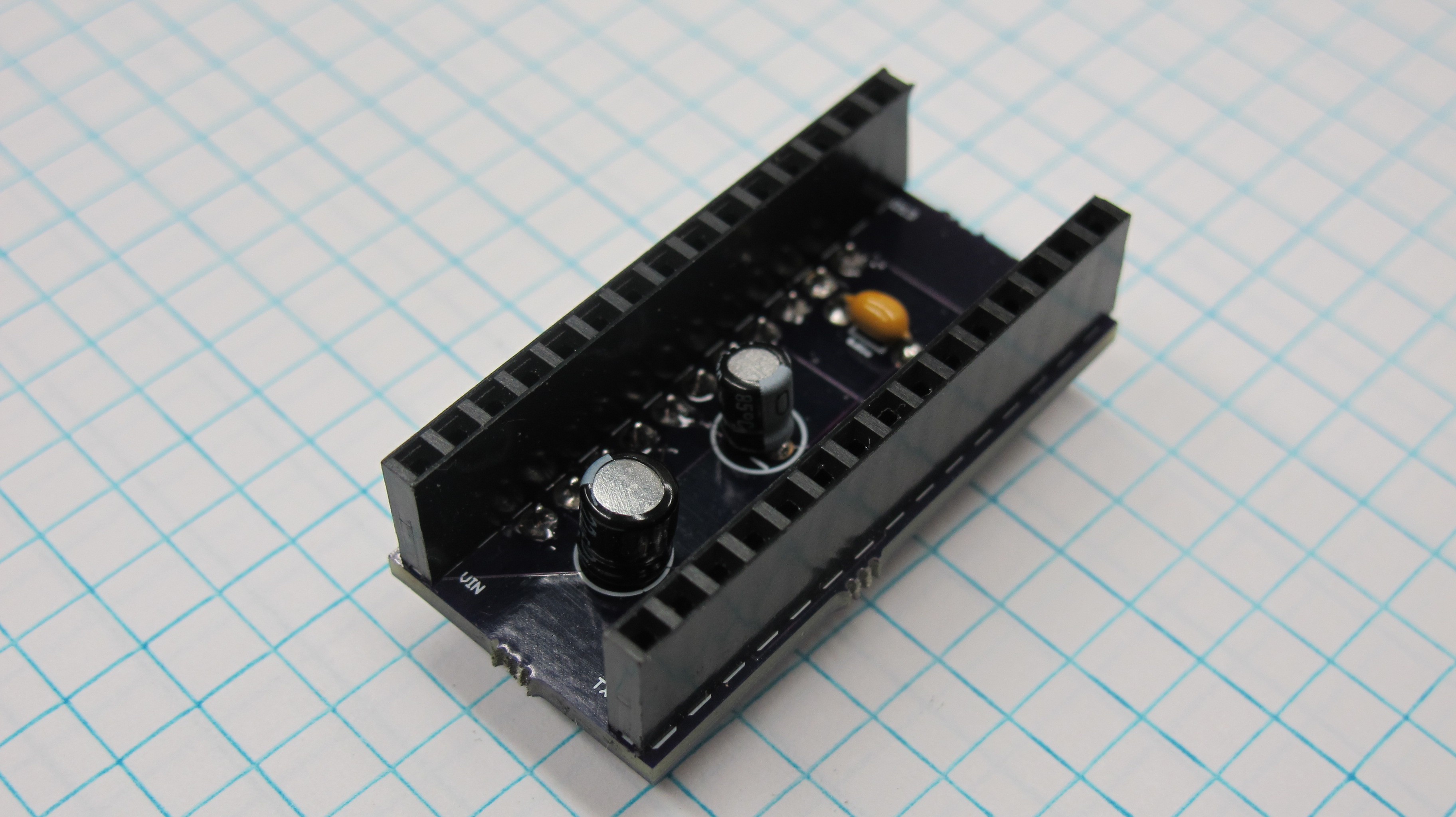
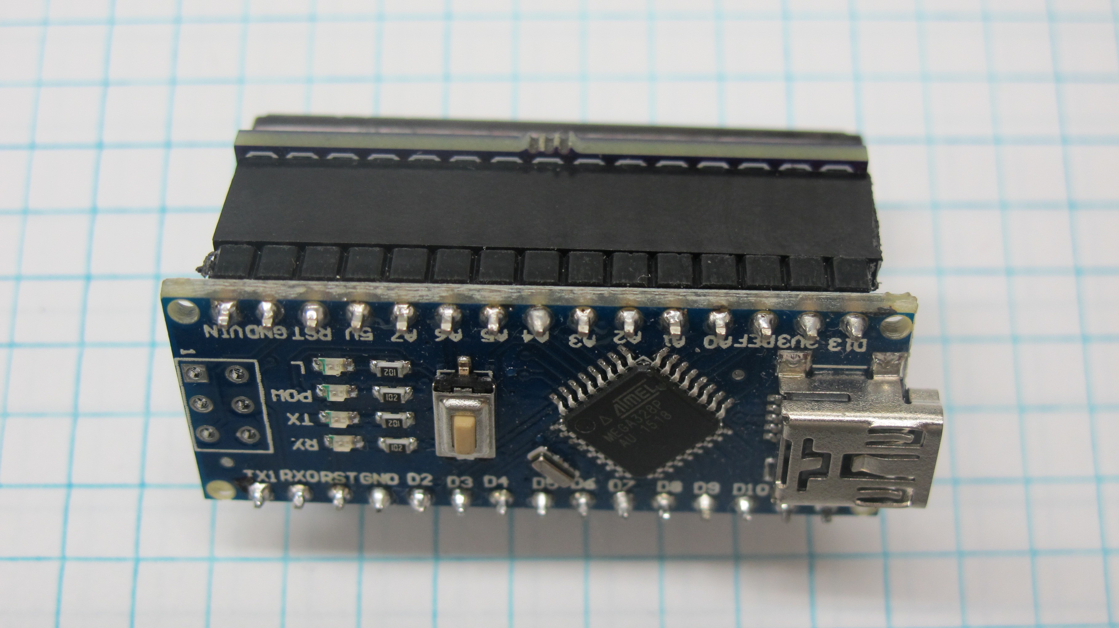
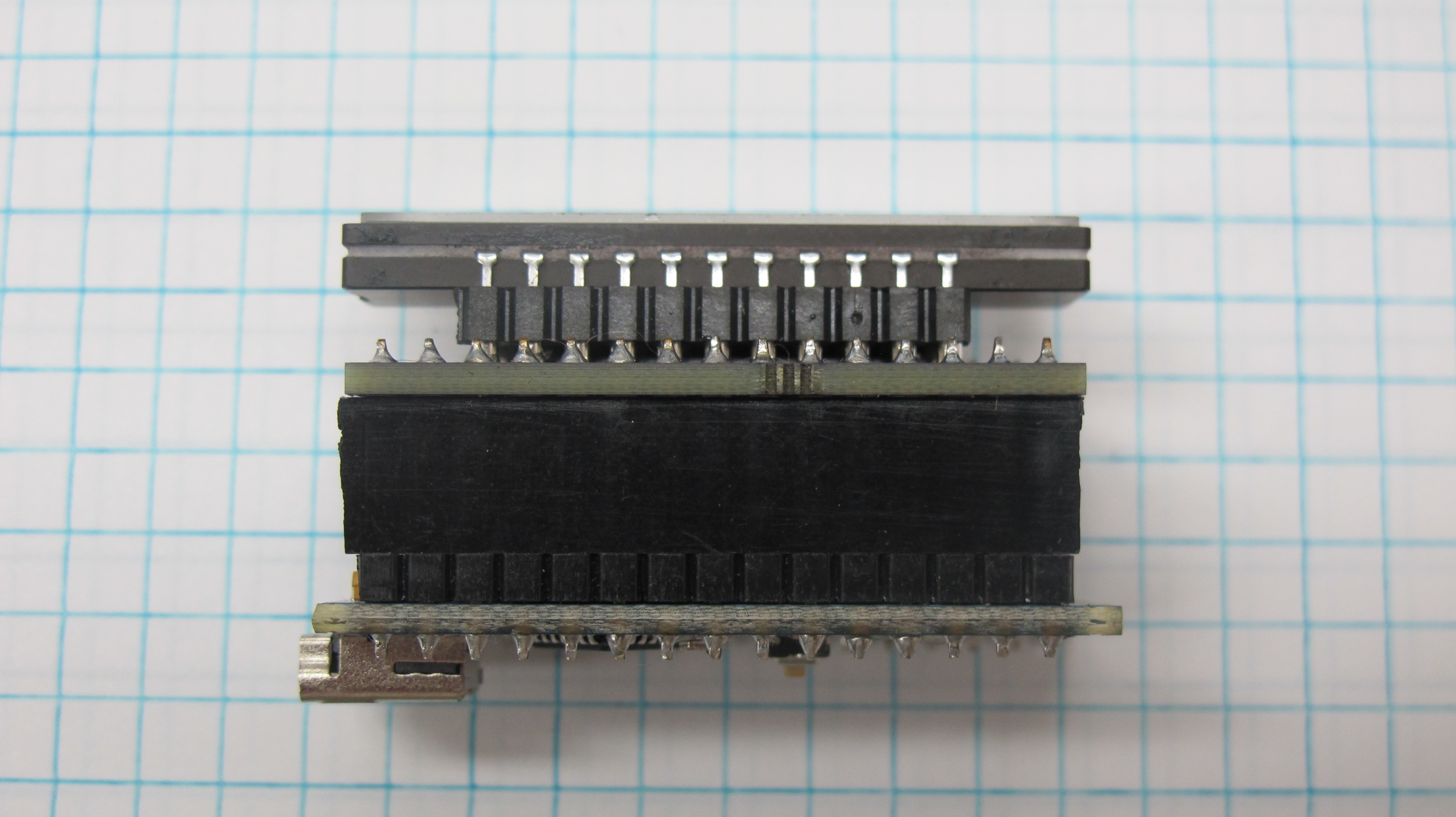
OSH Park PCB
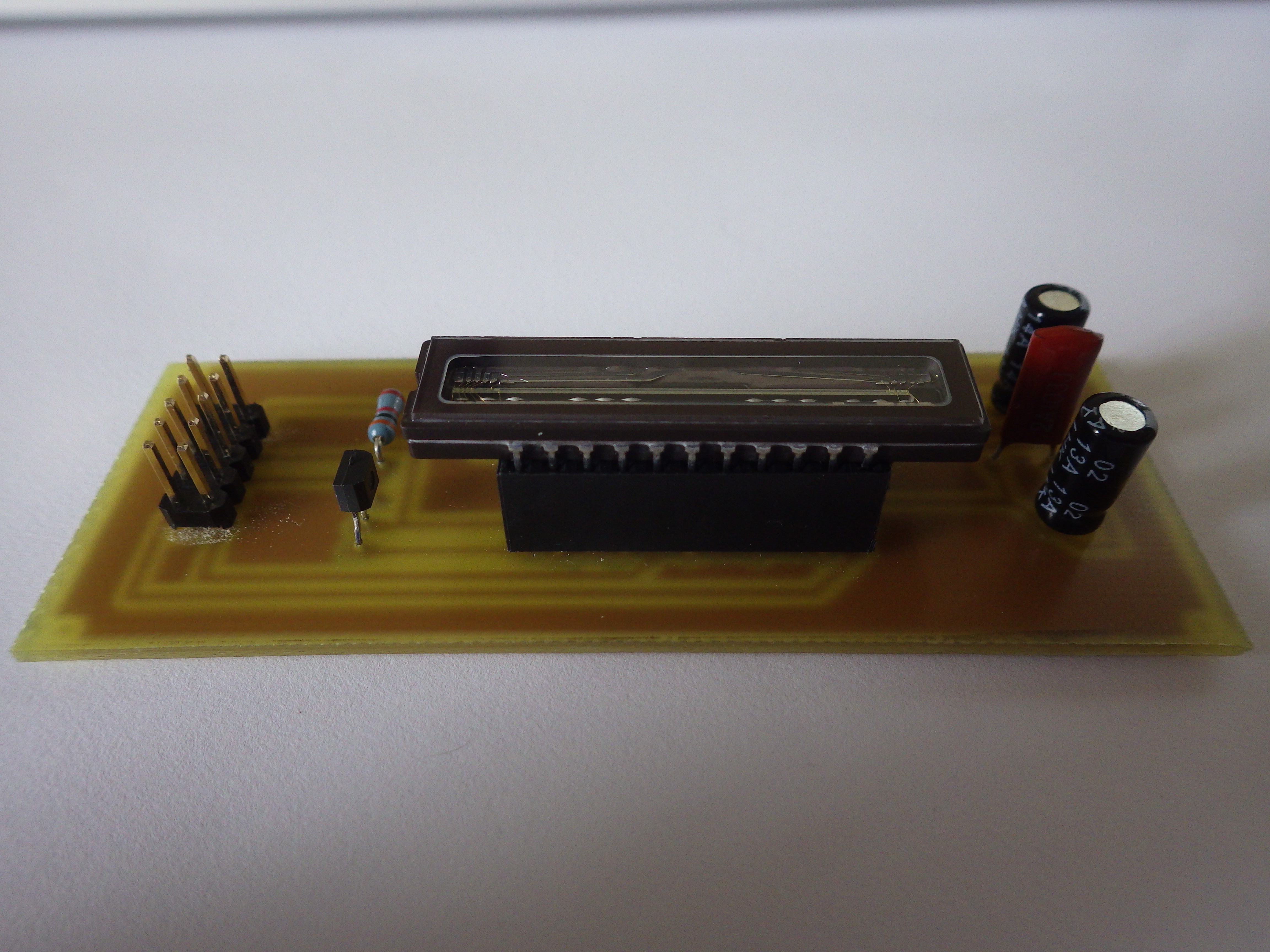
While the etched board was nice because it reduced the size of the board compared to the perf board design it still was too large for my design. So I went ahead and designed a CCD shield for the Arduino nano and sent the design off to OSH Park to get made. Initially I had designed the board with SMDs, however after multiple attempts and redesigns I was not able to get the board working. I went back to the drawing board and redesigned it using through hole components like the etched board, and had success. I also figured that it would be easier to other to replicate my design with through hole components rather than SMDs.
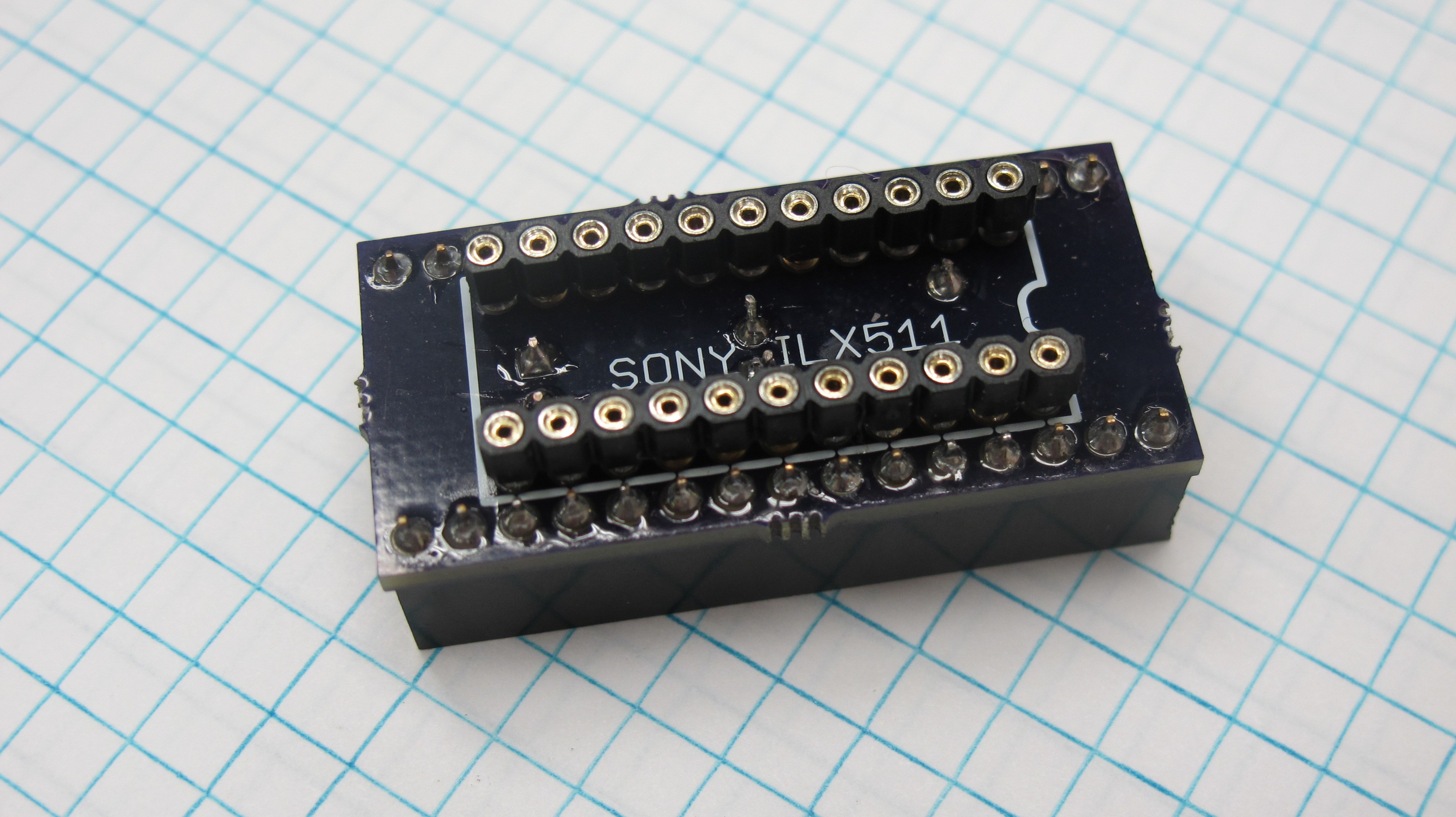
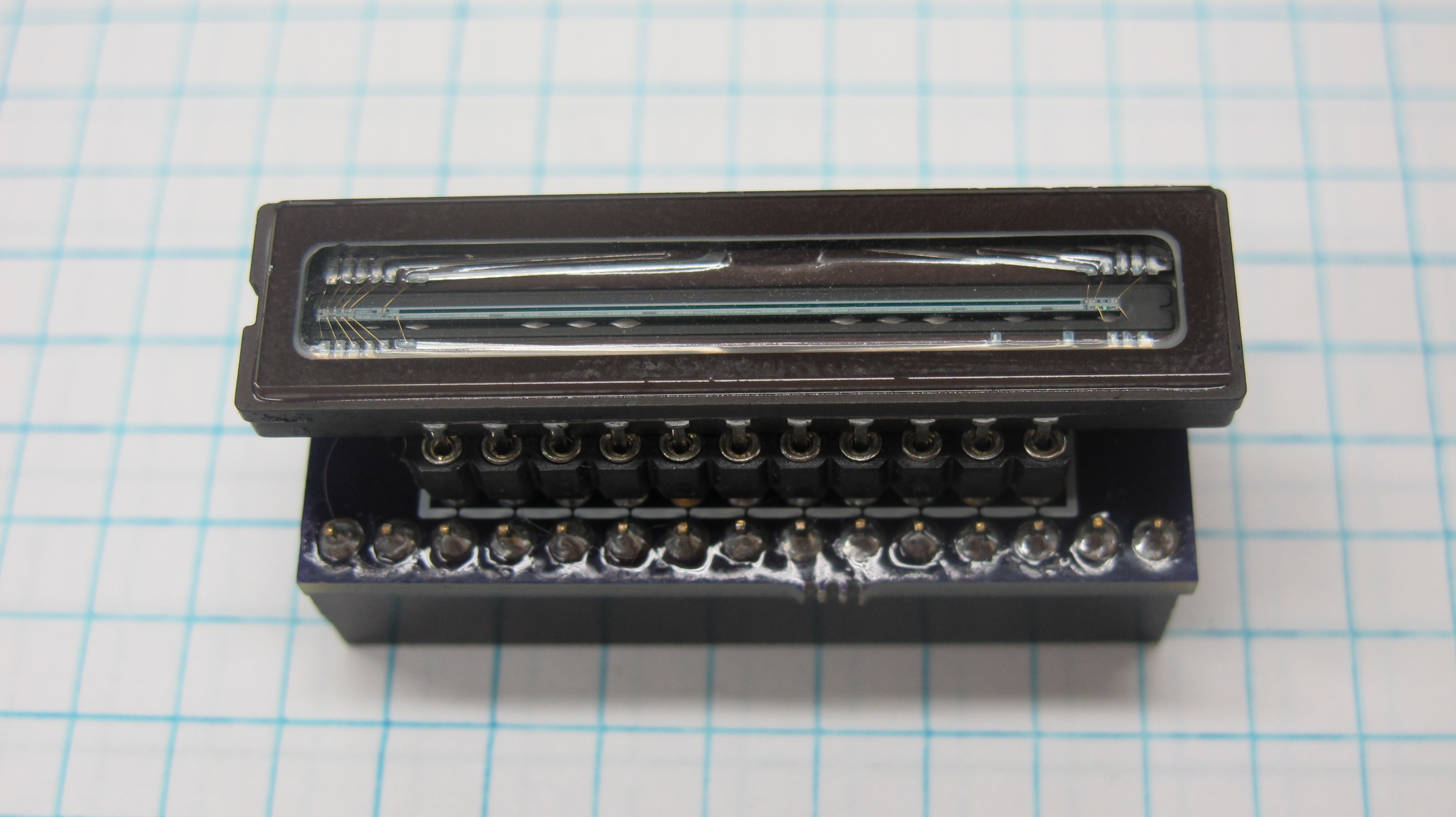
As you can see from the picture I used two different type of header for the shield, for the Arduino I use run of the mill square headers, however for the CCD I used round pin headers (here). I did this because I found that the square headers did not full come into contact with the CCD pins and because the round pins reduced the profile of the board a bit.
Discussions
Become a Hackaday.io Member
Create an account to leave a comment. Already have an account? Log In.