 ronald.sutherland
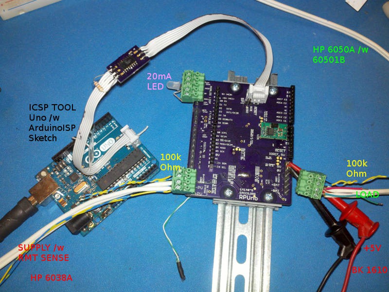
Assembled Version ^5 and did some Testing. Found a solder bridge near the LT3652 timer pin but that is nothing new. I think a stencil would help, rather than the syringe for solder paste. Ran the electronic load in voltage mode at 12.8V to simulate a battery and a supply set for 20V@1.1A to simulate the PV. Moving the shutdown thermistor (the green and white twisted wires from under board) off board looks like it can run all day at 1.3A. This is good news for the RPUpi board.
Discussions
Become a Hackaday.io Member
Create an account to leave a comment. Already have an account? Log In.