 fl@C@
fl@C@
Been spending a little time hammering out the spherical mirror reflection angles.. Made a little .scad file that pretty well simulates the ray paths for a given incident angle and shows where to reflected rays are.. This is of course, going into the spectrometer designer so people can use whatever mirrors they can grab and plug that into openSCAD and it'll spit out a spectrometer ready to print based on your optics...
Here's a little gif showing the incident angle changing...and the reflected rays acting accordingly..

Here's the code to generate this example.. It has a couple limitations, but I don't anticipate two axis angles, and to compensate for the mirror rotation, you can just change the angle of incidence..
/*
Limitations to this....
	Only two dimensional for now..
	Doesn't compensate for changing mirror angle..mostly..yet...
*/

//animate
function saw(t) = 1 - 2*abs(t-0.5);

pi = 3.14159265359;
FM_D = 50;		// focusingMirror Diameter
FM_EFL = 100;		// focusingMirror Effective Focal Length
FM_R = 200;		// focusingMirror Radius
FM_ET = 6;		// focusingMirror Edge Thickness
FM_Xr = 90;		// focusingMirror X rotation - up and down
FM_Yr = 0;		// focusingMirror Y rotation - rotates around normal
FM_Zr = 90;		// focusingMirror Z rotation - left to right
FM_Xp = 0;		// focusingMirror X position
FM_Yp = 0;		// focusingMirror Y position
FM_Zp = 0;		// focusingMirror Z position

incidentAngle = 60;	// angle of incoming light
numberOfRays = 45;	// number of rays to draw
rayStep = 5;		// distance between rays

module mirror(){
	difference(){
		translate([FM_Xp,FM_Yp,FM_Zp]) cylinder(d=FM_D,h=FM_ET,$fn=100,center=true);
		translate([FM_Xp,FM_Yp,(FM_Zp+FM_EFL)-0.5]) rotate([0,90,0]) color("lightblue") sphere(d=FM_R,$fn=100,center=true);
	}
	translate([FM_Xp,FM_Yp,FM_Zp]) color("white") cylinder(r=.25,h=100);
	translate([FM_Xp,FM_Yp,FM_Zp+100]) color("white") sphere(r=1,$fn=100);
}

module ray(incident,height,cR,cG,rB){
	focalLength = FM_EFL;
	normal = atan(height/focalLength)+FM_Xr;
	reflected = normal - incident + FM_Xr;
	a = sqrt((height*height)+(FM_EFL*FM_EFL));
	b = (100 - a) + 3;
	//incidentRay
	translate([-b,0,height]) color([1,cG,cB]) rotate([0,incident,0]) cylinder(r=.2,h=focalLength*2);
	//mirrorNormal
	translate([-b,0,height]) color([cR,1,1]) rotate([0,normal,0]) cylinder(r=.05,h=focalLength*1.5);
	//reflectedRay
	translate([-b,0,height]) color([cR,1,cB]) rotate([0,reflected,0]) cylinder(r=.2,h=focalLength*2);
}

for (i=[-numberOfRays/2: rayStep :numberOfRays/2]){
	translate([-.5,0,0]) ray(saw($t)*70+20,i,0,0,0);
}

translate([-3,0,0]) rotate([FM_Xr,FM_Yr,FM_Zr]) mirror();
It works pretty well, and I should have this integrated into the near final version soon..
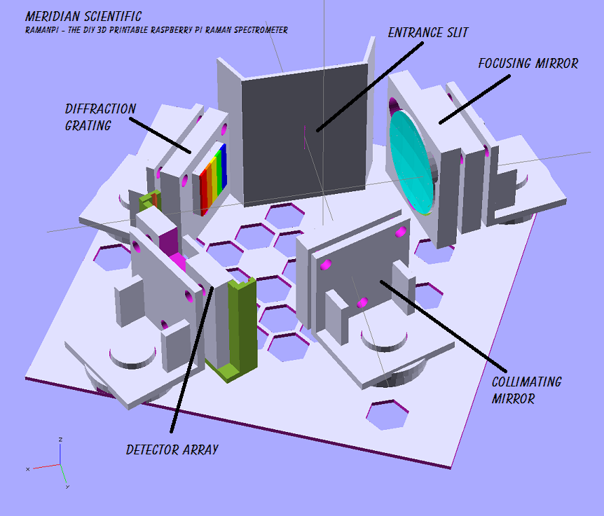
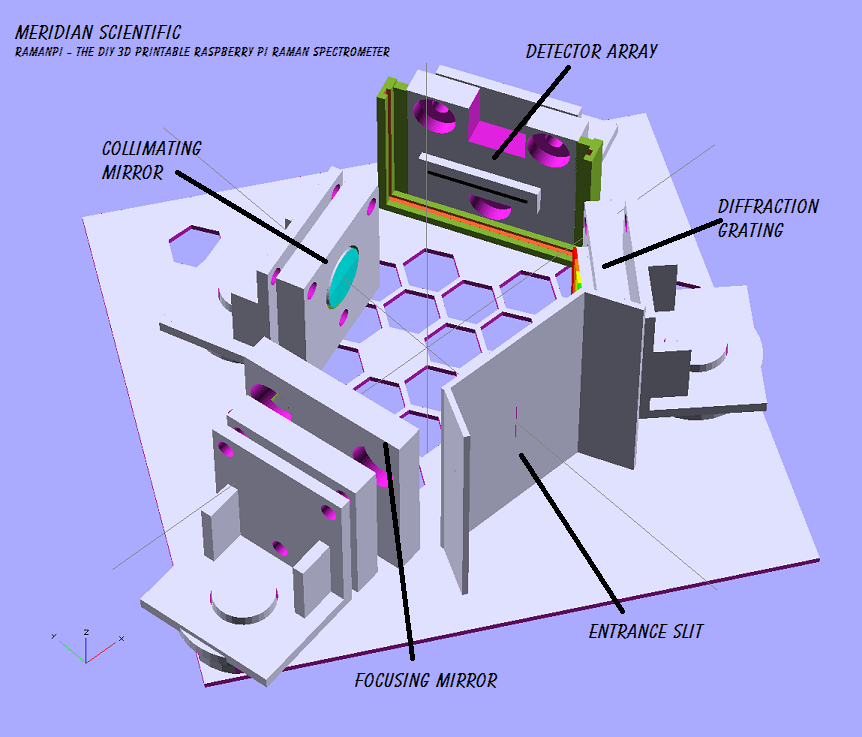
So, just to show I'm making progress in other areas as well... Here's what I am using right now to get some code and finalize my design for the spectrometer I'll be using.. As a result of the previous tests, this fits my optics, and has all the correct focal lengths and angles.. I am also testing baffling, etc. using this.. (The difference between this and the last setup is the base....it has a set geometry and will only allow for adjusting angles, not distances..which is proving useful over the previous setup..But, just like the previous test setup...this is a throwaway and will not be in the final design, just for tests....)

Discussions
Become a Hackaday.io Member
Create an account to leave a comment. Already have an account? Log In.