 fl@C@
fl@C@

Note: This log entry is a living document. I'll be updating this post to reflect the current configuration as time goes on.. There will also be a log at the end of the post noting modifications to the log, etc..
UPDATED-----> 09.25.2014

This log entry will instruct you on building the laserShutter Assembly..
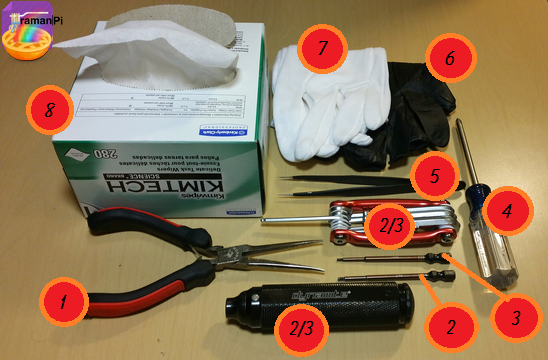
Tools Required:
- 1. Needle Nosed Pliers
- 2. 1.5mm Hex Driver
- 3. 5/64" Hex Driver
- 4. Philips Screwdriver
- 5. ESD Style Precision Tweezers
- 6. Nitrile Gloves
- 7. White Cotton Gloves
- 8. KimTech KimWipes
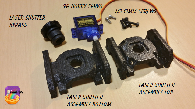
Components Required:
- Printed versions of the following 3D Printed Objects from the gitHub repository:
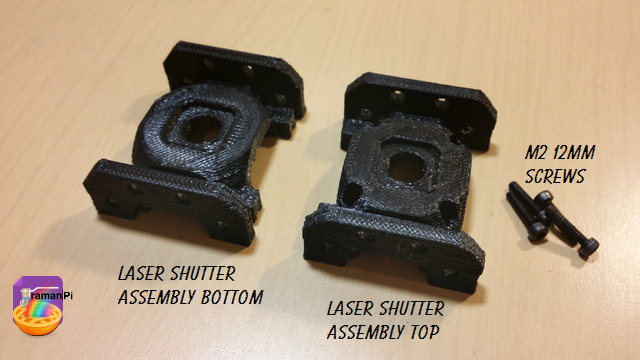
- (1x) optics_module_laserShutter_bottom
- (1x) optics_module_laserShutter_top
- (1x) optics_module_shutter_bypass
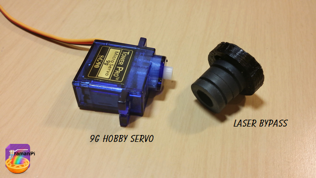
- (1x) 9g Hobby Servo
- (6x) M2 - 0.45 12.9mm Socket Cap Screws
Steps:
1. Print and clean up the plastic parts. Be sure to use the 3D printed part guidelines. All spurs and supports need to be cleaned as much as possible.
2. Grab the 9g Hobby Servo and the Laser Shutter Bypass and attach the Shutter Bypass to the servo.
3. Take the top and bottom halves of the laserShutter Assembly and four of the M2 12mm Screws.
4. Place the screws in the screw holes and tighten them in the following order.
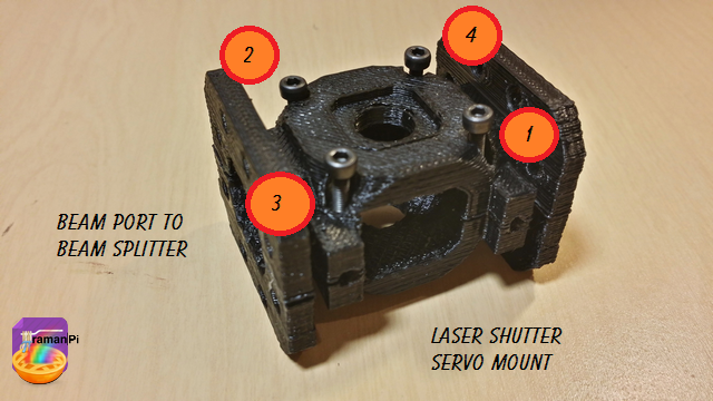
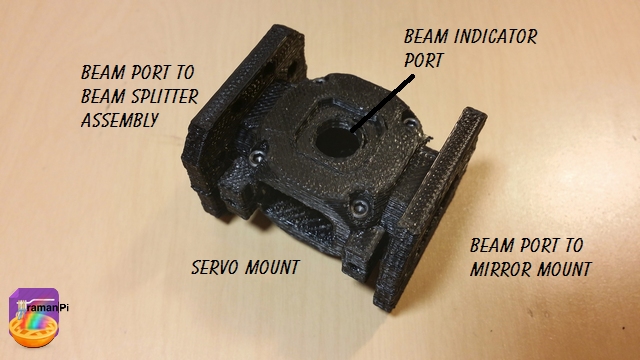
5. It should look like this. Make note the servo mount orientation...The servo head goes to the left of the mount from the perspective below..You can see the hole extends further in that direction.
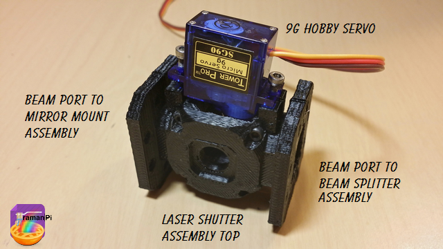
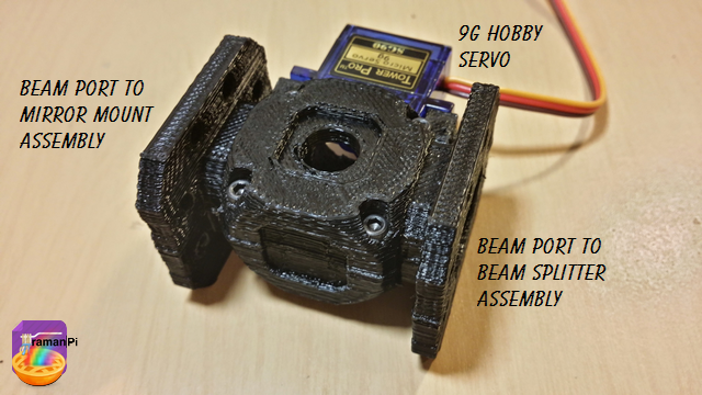
6. Place the servo and bypass into the servo mount.
That completes this part!
Set aside and move to next build!
You can close this tab or return to the build instructions here!

UPDATE LOG:
09.25.2014 - New Entry
Discussions
Become a Hackaday.io Member
Create an account to leave a comment. Already have an account? Log In.