fl@C@
fl@C@-
PCB Designs are DONE
10/16/2014 at 16:58 • 0 comments![]()
So, I have been working toward getting the schematics nailed down and the board layouts done.. Done.. They are all be available on Oshpark, or in the gitHub repo right now.
The living logs for each board has been updated and the main project details should reflect the latest as well.. Now maybe I can move on to make some more interesting stuff!!
controlBoard project log
![]()
powerControlBoard project log
![]()
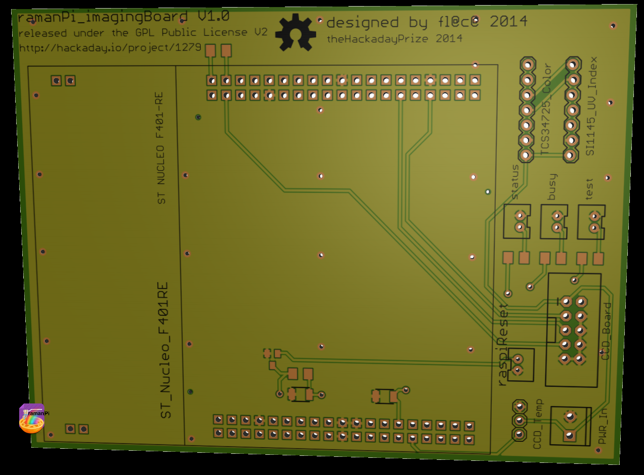
imagingBoard (including CCD board) project log
![]()
![]()
interfaceBoard project log
![]()
![]()
-
plot.ly - sharing data on the internet with your colleagues and friends
10/16/2014 at 16:27 • 4 comments![]()
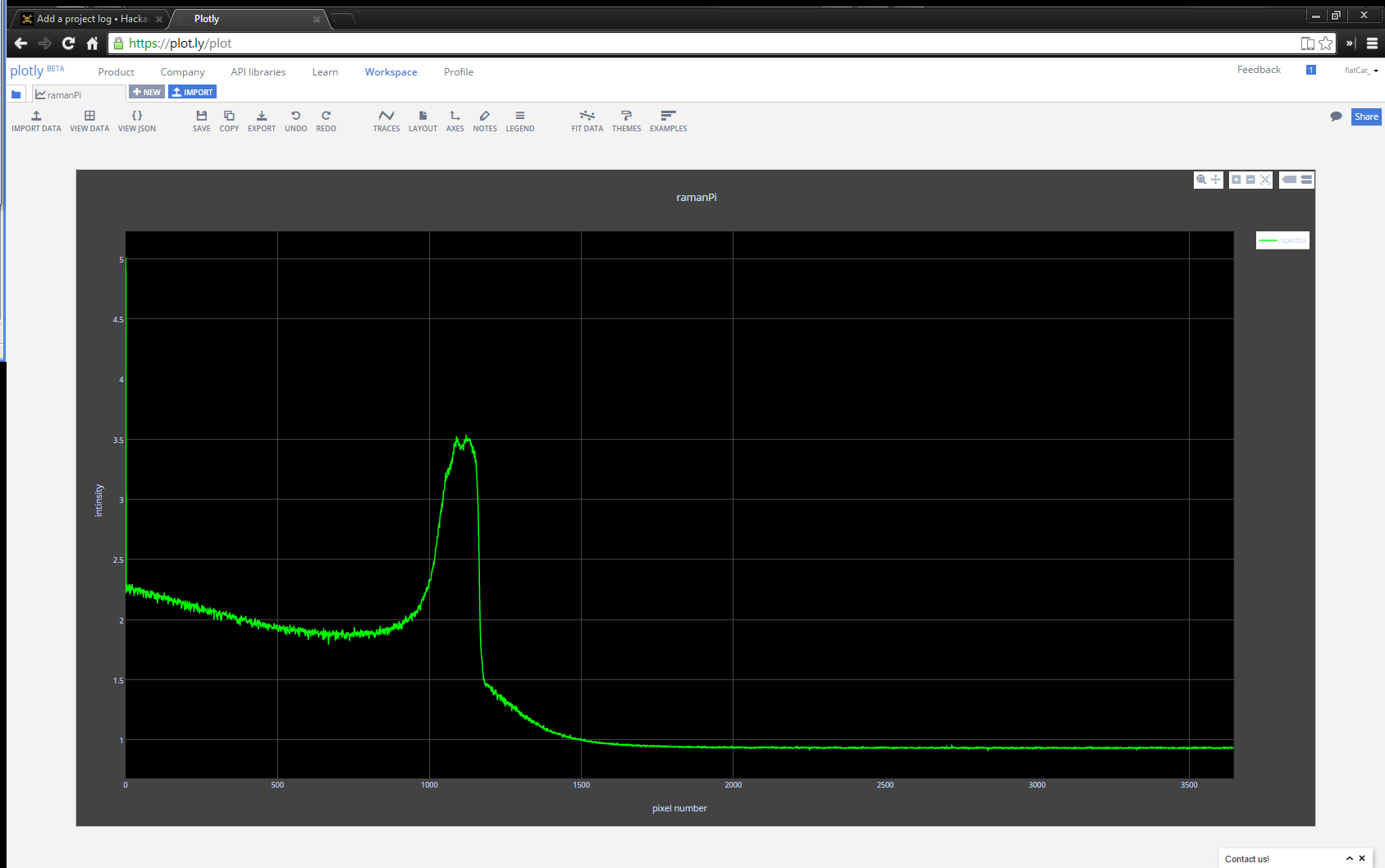
Well, here it is... I have been working on the software a bit.. Right now I am focusing on the main parts and will branch out.. For now, I have the raman system aquiring spectra and displaying it in a window on the remote terminal/laptop/workstation/whatever you decide to use...and it posts the same data to plot.ly.... Plot.ly in case you're not familiar is pretty cool.. It allows you to push data and create nice graphs and stuff from your devices....and share them. Here's a link to my first success getting ramanPi to post data... HERE ..
Now, here's why this is so cool...and essential to the operation.. First and foremost, this allows anyone to view the output......from anywhere..on ANY device that has a web browser....AND they can collaborate.... That means for instance......You have a ramanPi, no computer...but you have a cell phone with a browser..with your sample in the cuvette in the ramanPi, use the touch panel to start an analysis.....(you could telnet into it and start it that way, so I might actually add some process in here that allows other devices to do this as well) ramanPi hits the sample with the laser, takes its spectra and so on.. when it's done... it pumps the data straight to plot.ly and notifies you on twitter along with your friends and colleagues... You take a look and there it is... It'll even show the spectral databases spectra overlayed as a 2nd trace.. to further compare!
Ok..Here's another example.. You have your ramanPi, a laptop and you're working with a friend across country....who needs the data.. You put your sample in, and in a short time the spectra is available to them and anyone else who you want..
I'm very excited about this portion.. it really allows a LOT of collaboration with ramanPi... Want that distributed spectral internet database? Here's a start.. I'll be working on other sharing methods soon.. Next step, pulling spectral data from the internet databases to allow for matching and identification...then overlaying that on the output here in plot.ly and on your workstation...!
Here's a plot from the website...
![]()
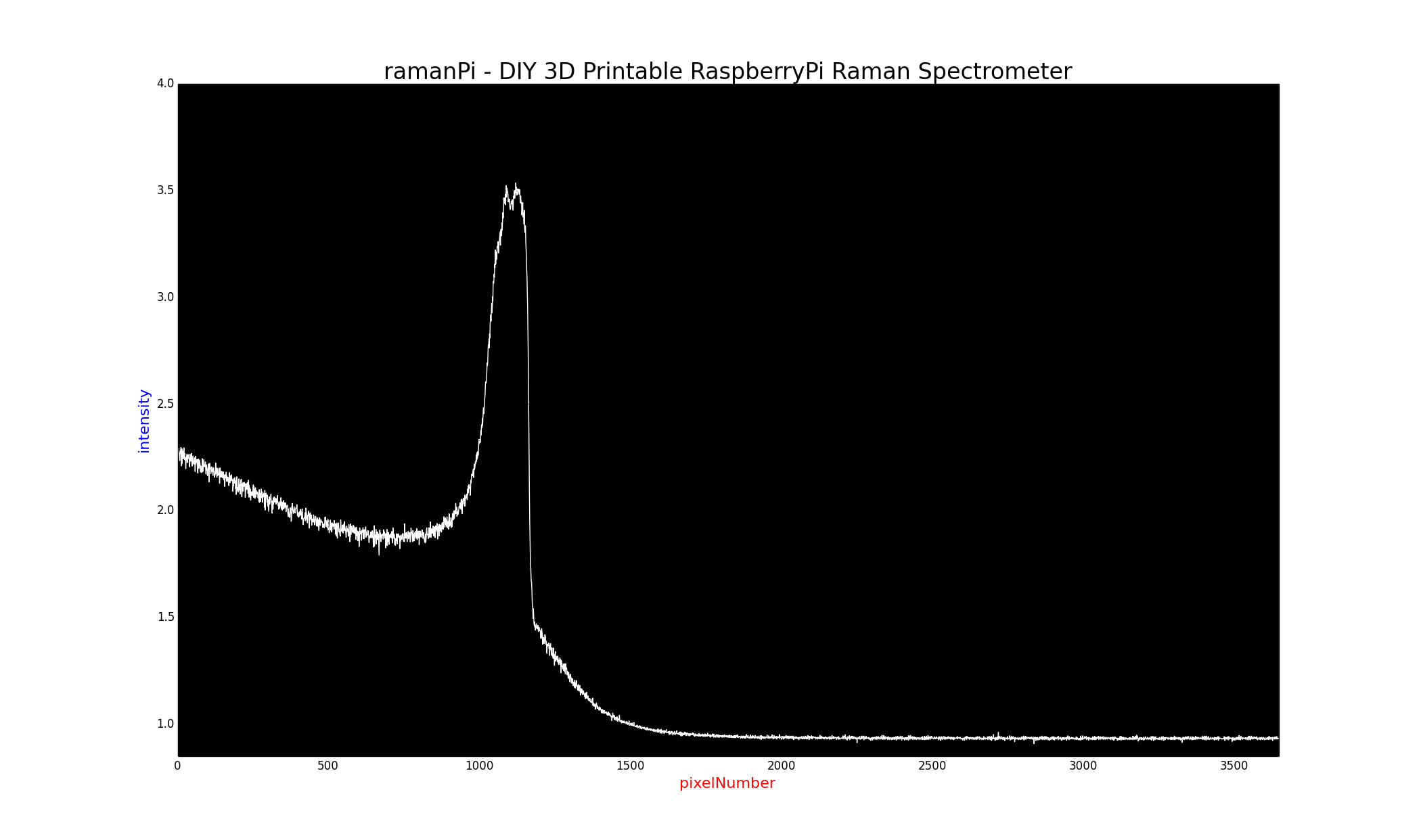
Here's a plot from the workstation of the same spectra... (the scale is set different in case your're wondering why the workstation is stronger)
![]()
As always, I would love to hear anything anyone has to say about this..!
![]()
-
New Photos
09/29/2014 at 05:58 • 0 comments![]()
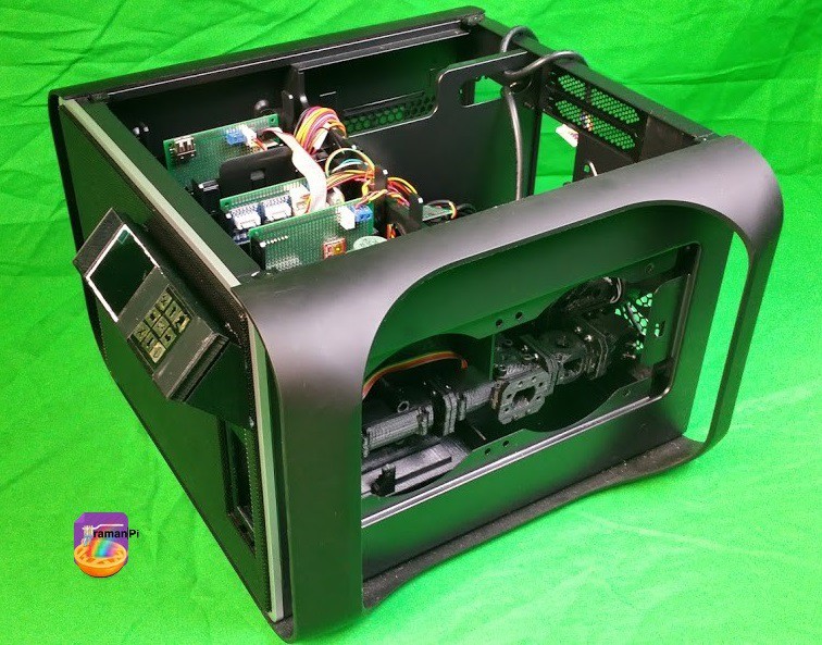
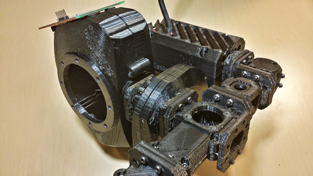
I just wanted to take the opportunity to post a few pictures of the system as it's shaping up..
A side shot with the top and the side panel removed...
![]()
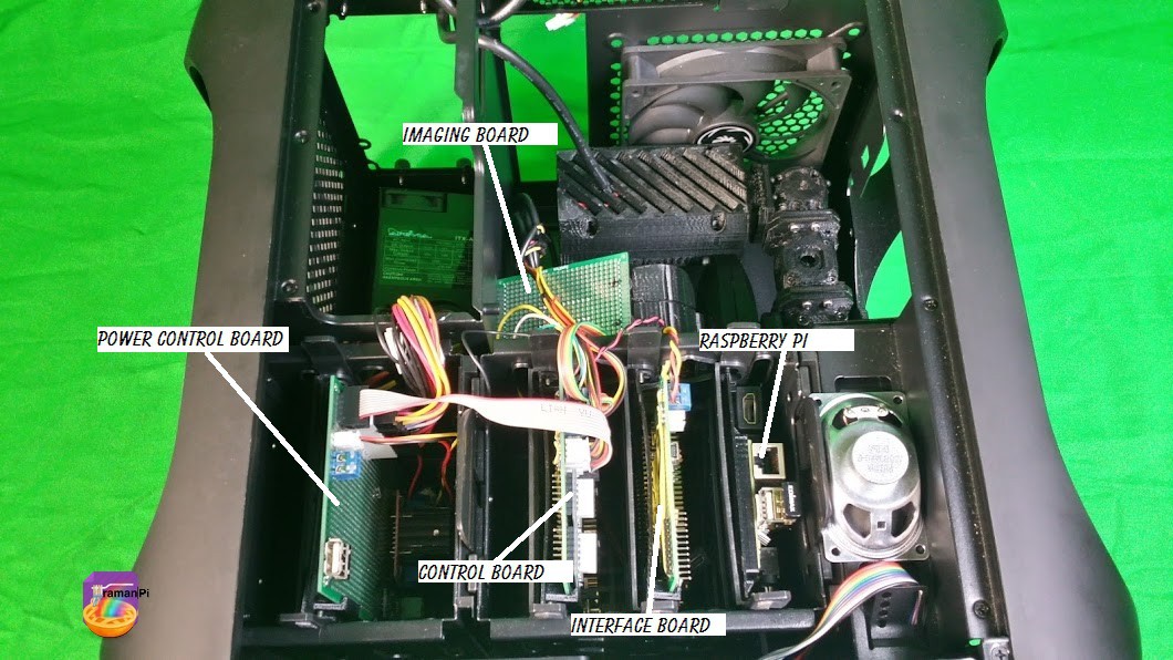
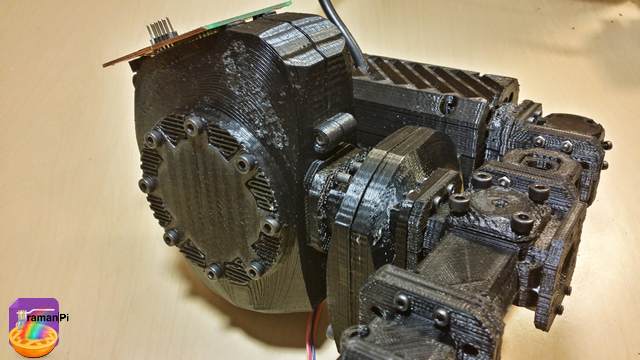
And overhead view showing the electronics....
![]()
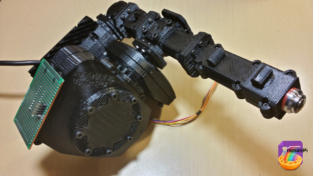
A nice shot with 'remote terminal'..
![]()
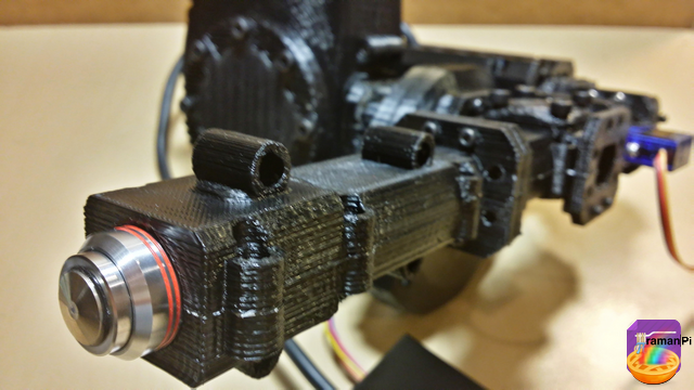
It's been great working on this thing...
![]()
-
interfaceBoard - schematic and board information
09/29/2014 at 01:55 • 0 comments![]()
![]()
Note: This log entry is a living document. I'll be updating this post to reflect the current configuration as time goes on.. There will also be a log at the end of the post noting modifications to the log, etc..
UPDATED-----> 09.28.2014
![]()
This log entry is where I will keep current information regarding the schematic, board layout and other details about the imagingBoard electronics and firmware.. I will reference this log entry in the 'details' section of the project page.. This log entry will probably change from time to time to reflect the current status of the imagingBoard. If you're interested, it might be worth a bookmark..
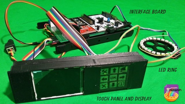
The function of the interfaceBoard is as follows:
- Arduino Pro Mini (for Adafruit RGB LED Ring which animates depending on activity)
- ILI9341 2.2" TFT LCD Color Display
- Capacitive Touch Panel with 12 'Buttons' using MPR121 touch controller
- Displays system status and mini control interface
- Accepts user input to open/close cuvette tray, etc..
- LED Ring provides feedback regarding status, etc..
Here is what the current interfaceBoard looks like..
![]()
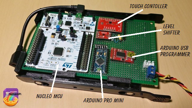
A closer view of the board itself.
![]()
The eagle files are available on the gitHub repository..
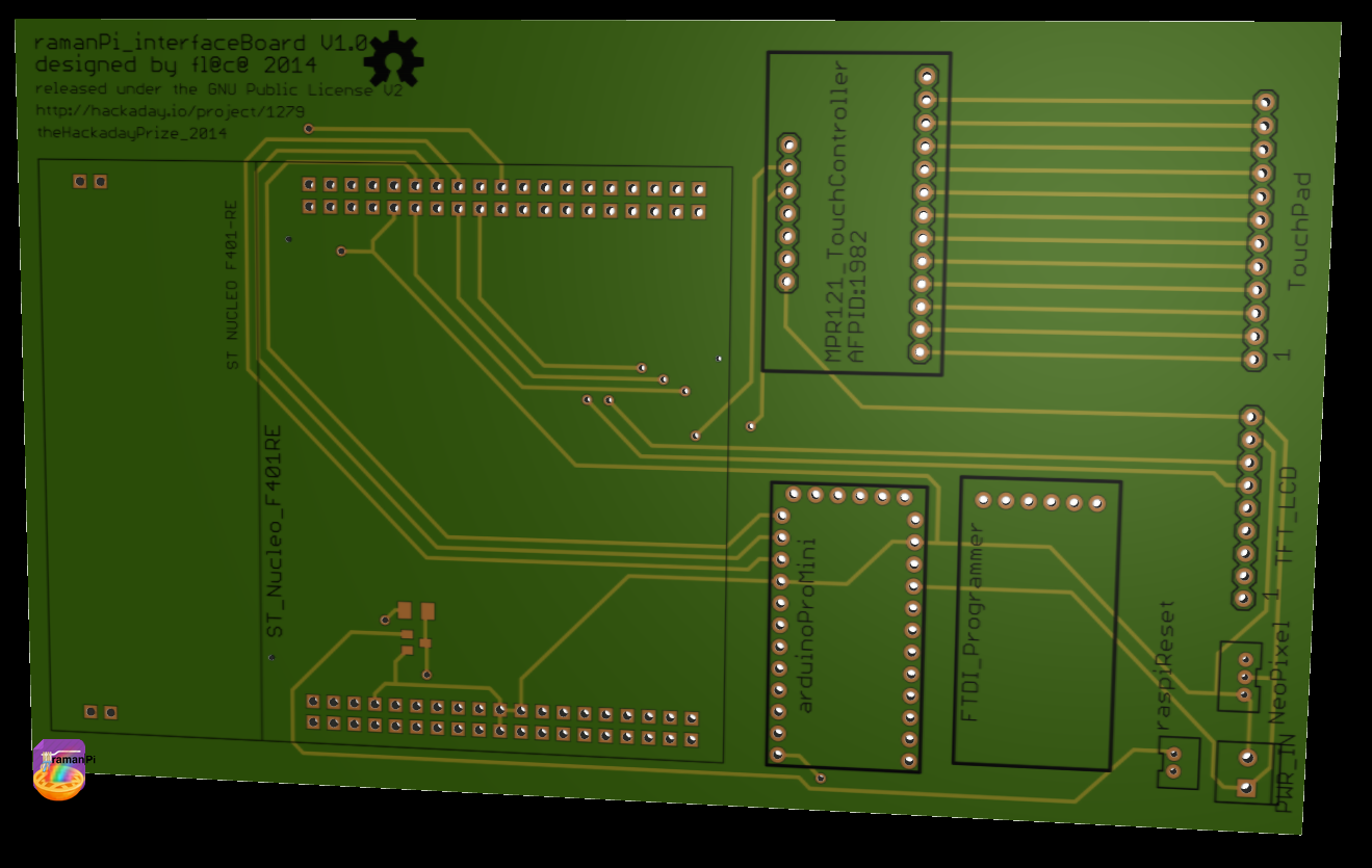
Here is a rendering of the interfaceBoard
Top
![]()
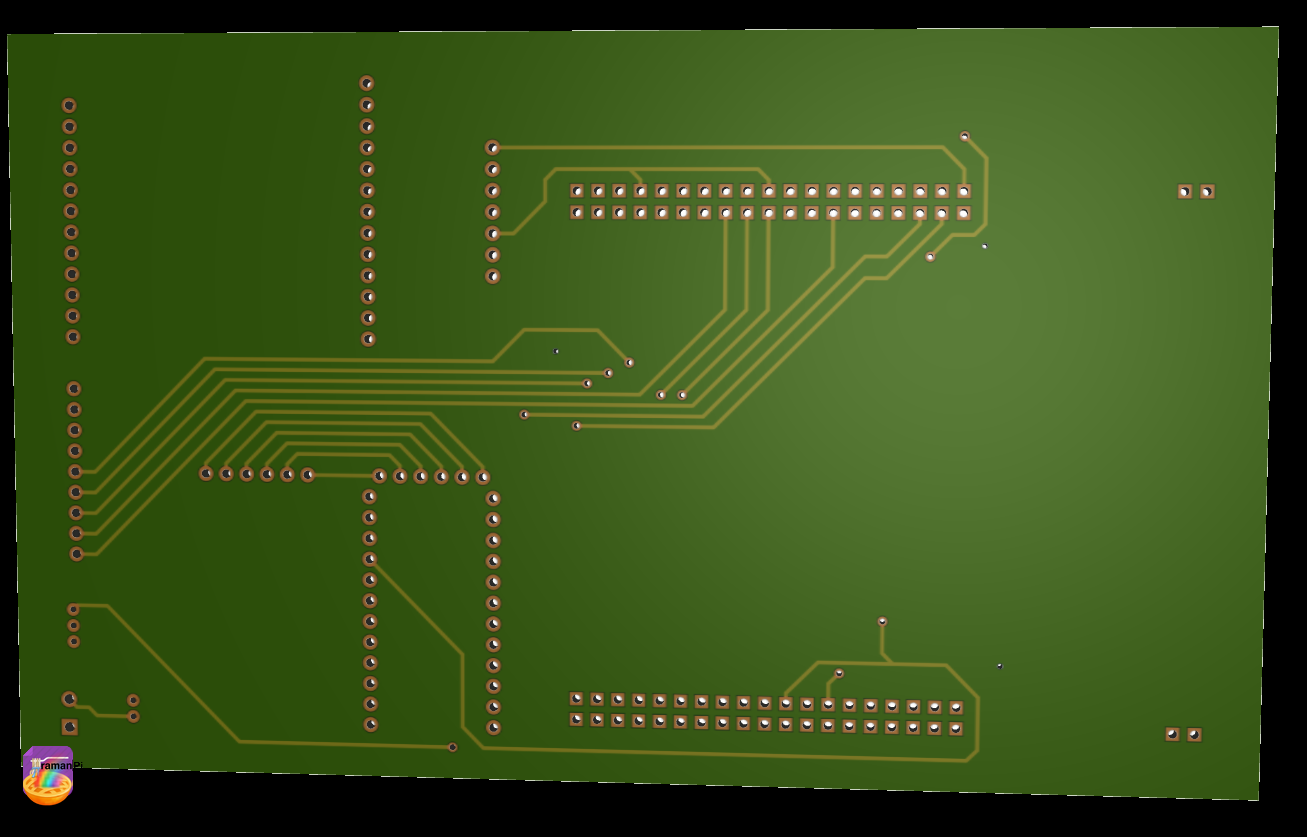
Bottom
![]()
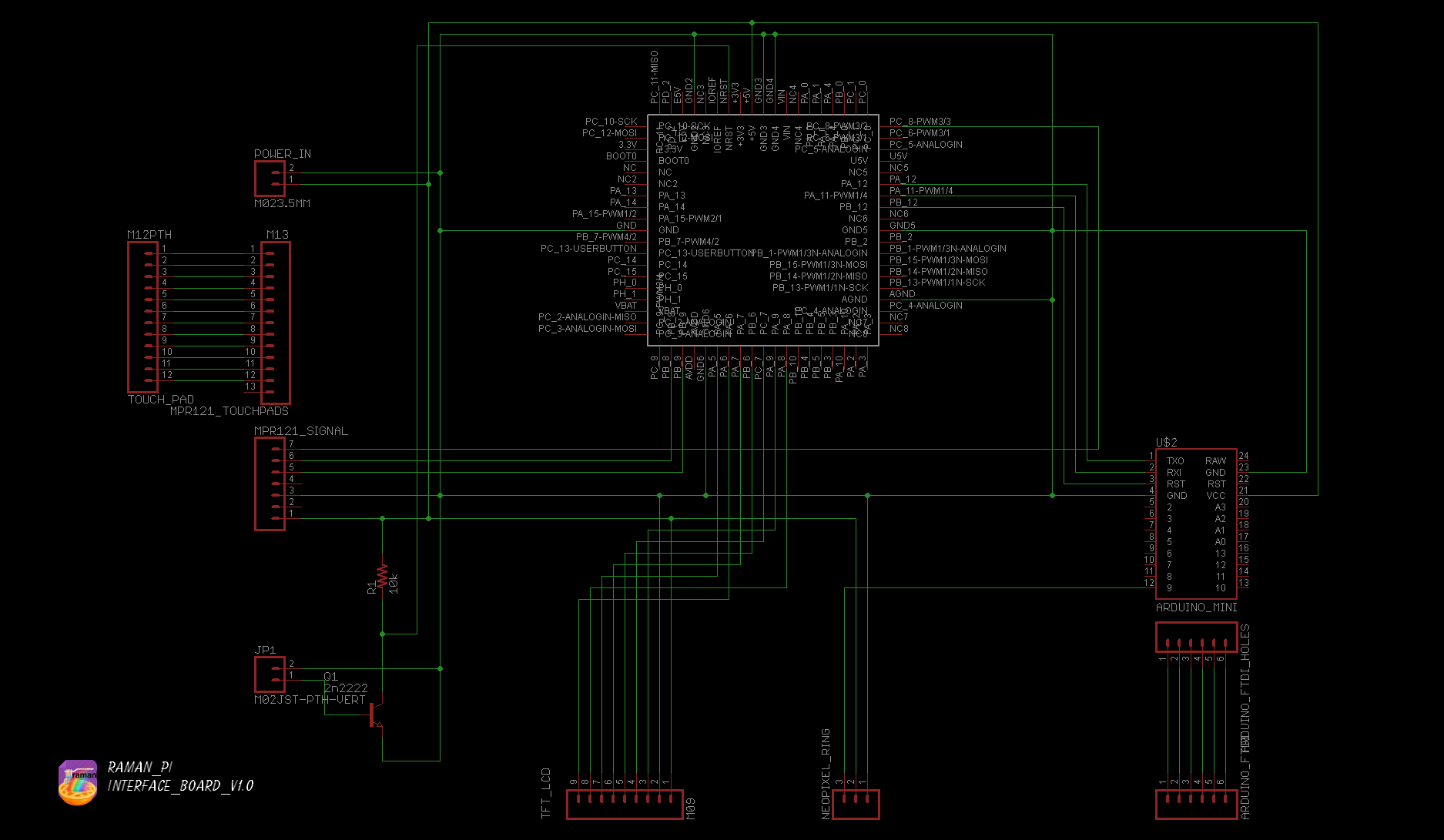
Here is the schematic..
![]()
The eagle files, and the firmware are located in the gitHub
- Hardware: gitHub repository
- Firmware: gitHub repository
The board consists of .. An ST Nucelo F401RE microcontroller, an Arudino Pro Mini, a 2.2" TFT LCD based on the ILI9341, and an MPR121 touch controller. It also has the USB FTDI for programming the arudino from the raspberryPi.
Keep an eye out, since there will be updates here...!
![]()
UPDATE LOG:
09.28.2014 - Added living document info
10.15.2014 - Added new schematics and board renderings
-
powerControlBoard - schematic and board information
09/29/2014 at 01:45 • 0 comments![]()
![]()
Note: This log entry is a living document. I'll be updating this post to reflect the current configuration as time goes on.. There will also be a log at the end of the post noting modifications to the log, etc..
UPDATED-----> 10.15.2014
![]()
This log entry is where I will keep current information regarding the schematic, board layout and other details about the imagingBoard electronics and firmware.. I will reference this log entry in the 'details' section of the project page.. This log entry will probably change from time to time to reflect the current status of the imagingBoard. If you're interested, it might be worth a bookmark..
The function of the powerControlBoard is as follows:
- Accepts power from main power supply and distributed it to other boards
- Contains the L298 HBridge for the imaging and cuvette peltiers
- Current Sensor monitors peltier current draw
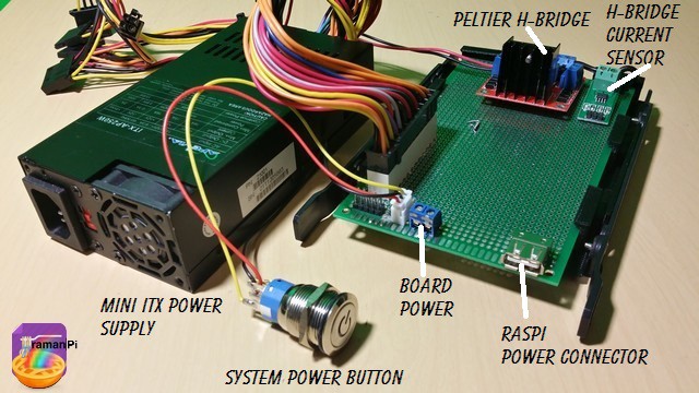
Here is what the current powerControlBoard looks like..
![]()
The eagle files are located in the gitHub repository..
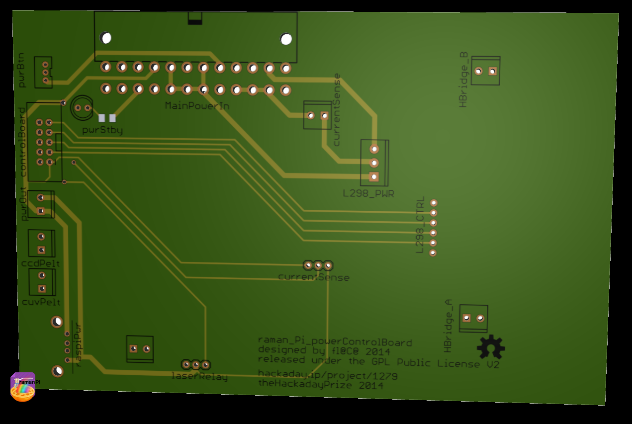
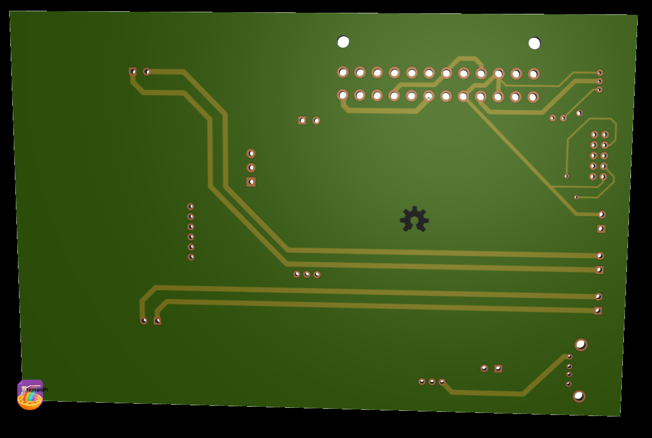
Here is the board rendering..
Top
![]()
Bottom
![]()
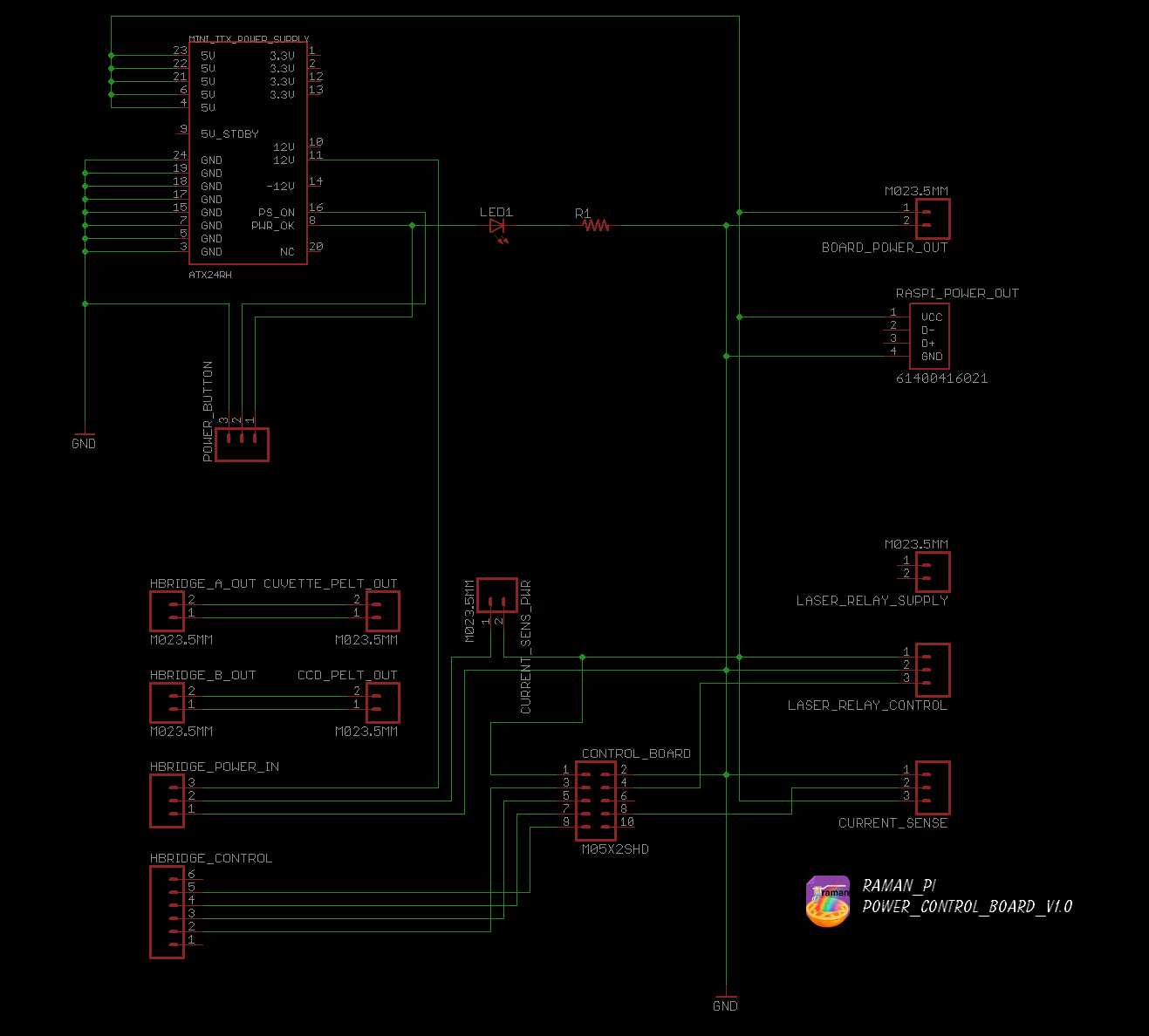
Here is the schematic..
![]()
The eagle files, and the firmware are located in the gitHub
- Hardware: gitHub repository
The board consists of the connector for the ITX power supply, power connector for the raspberryPi, power connector for the other boards, and a control cable from the controlBoard for the H-Bridge and Current Sensor both of which also live on this board..
Keep an eye out, since there will be updates here...!
![]()
UPDATE LOG:
09.28.2014 - Added living document info
10.15.2014 - Added new schematic and board renderings
-
THP Semifinal Video (with transcript)
09/29/2014 at 00:33 • 0 comments![]()
THP Semifinal Video
Below is the transcript for this video... Sorry it runs a little fast, but there's a ton of information!! =)
ramanPi started as a project to fill a need I had for another project I am still working on. I had to obtain the bond angle and raman shifts for samples I was producing. That called for a raman spectrometer and access to one is financially prohibitive as even used units run tens of thousands of dollars. I set out to build a raman spectrometer with no knowledge on the subject whatsoever.
Since I started the design has gone through four phases.. I started with the misconception I was going to be able to obtain a raman signal with a more rudimentary setup..I then moved to the thought of using the raspberryPi camera module and a couple edge filters. That notion might be fine with some extra time..I progressed into a series of lens mounts on stands in an optical bench type configuration.Some feedback from the hackaday crowd, and a couple late nights, and it evolved into what it is today..
ramanPi is fully open source, there is absolutely no secret sauce. Everything is available to everyone. I also used several open source libraries for the various sensors and other devices the system is composed of. There are also many open source libraries used in both the raspberryPi software as well as the client software.
I had no idea I would take the design so far when I first thought about this project. And I look at what I have now, and wow.. I think the 3D printed parts came out just amazing. I am very happy with the spectrometer design. The fact that I was able to write the .SCAD file to automatically change dimensions, shape, and angle for whichever optics you decide to use is way more than I ever hoped possible!
ramanPi is centered around a raspberryPi, which is connected to the internet via a WiFi adapter. It communicates with the client software as well as multiple online spectral databases to determine a match for the spectra of the compound under test. The client software and the raspberryPi exchange data which is displayed on the users workstation, phone or tablet. The client software also gives the user the ability to store that data in the cloud, share it with friends or colleagues and make graphs or presentations with it.! The client software can use whatever internet connection the device has. Without an internet connection, ramanPi wouldn’t do much beyond display spectra from a sample on a local screen. It would not be able to identify what compound you are testing.
There are a number of other uses for ramanPi as a whole as well as many components within the device. The entire system has many applications such as mineral identification, cancer research, biological studies, and a ton of others.. You can extend that by adding future expansions I have planned, such as fiber optics adapters, side scatter detection, and a few others! The spectrometer portion can be used completely independently of the whole system. Without modification,it can be connected to a PC through USB without the rest of the system and work as a fully functional spectrometer! To top that, you can also add future adapters to the spectrometer for many additional features such as fiber optics.
The design can be reproduced very easily. For high volume production you could use injection molding to make the 3D parts. 3D printing for lower quantities would be a totally acceptable option. The optics are right off the shelf and can be purchased individually or in bulk from companies like Edmund Optics. The electronics are very easy to source and they will be integrated down to two boards for the whole system very soon. The CCD is inexpensive as well and is the same version commercial systems use. It is a complex device, but there is really not much to it in this sense.
I made every engineering choice with the idea of reproducibility in mind. I kept the design as simple as possible while keeping the integrity of a raman spectrometer with a respectable spectral resolution. I also made sure the design was physically sturdy and would withstand the test of time.
I kept the parts modular, simple and in a format that is fairly commonly used in the industry. The individual parts are easy to work with and the overall cost is unbelievably low in comparison to the alternative.
The optical assembly and 3D parts are the showcase of this system in respect to ingenuity and innovation. This is a one of a kind system and the only DIY raman spectrometer design available, let alone open source. I have received a lot of positive feedback from many people who have tried to create a raman system with no success.. I hope to not let them down!
The modularity, ability to modify and tailor the parts to suit your needs, the use of two inexpensive edge filters as opposed to one expensive notch filter all are testaments to the innovation. The spectrometer has been called a work of art. There’s really nothing else like it. Not even commercial systems have this many features!
I made sure to design every part of this device so my own mother could use it without wondering what means what. The interface is very simple to understand and very easy to get up and running spectra right away! You don’t even need to interpret a squiggly line and figure out what compound it is, the system will verbally speak it to you when it has identified it! The client software should be available on a PC to start, then eventually phones, tablets and even chromebooks!
The main electronics consists of a control board, the power control board, an interface board, the imaging board, and the raspberryPi. The control, interface, and imaging boards are based on ST Micro STM32 Nucleo F401RE microcontrollers. The control board handles the nuts and bolts of the system, moving motors and reading sensors and so on. The interface board controls the display, the touch panel, audio and the RGB LEDs. The imaging board manages the CCD and reading spectra from the spectrometer. All the boards are connected to the raspberryPi via USB and their functions are dependent upon one another. The raspberryPi communicates to the internet, databases, and the client(s).
Currently, the control board functionally monitors the laser and cuvette temperatures via two DS18B20 sensors, controls the L298 HBridge which drives the two peltier devices. One peltier cools the ccd and the other both cools and heats the cuvette to maintain its temperature using a PID controller. It also monitors the current draw for the two peltiers. In addition, it reads the cuvette ends stops, controls the laser shutter servo, and both the TTL line and power relay for the laser. Priorities have kept the laser good TEMT6000 sensor, the BMP180, and the laser color sensor on the back burner.
The power control board currently performs all of its planned duties which include taking in power from the mini itx power supply, supplying power to all of the other boards, housing the L298 HBridge, the current sensor and controls the system power with a nice stainless steel button.
The interface board also currently performs all of its planned duties controlling the TFT LCD display, and taking input from the touch sensitive keypad..it also communicates that data to the raspberryPi when it has any user input. In addition it controls the arduino pro mini that drives the RGB LED ring.
The imaging board is another success story with it’s duties of controlling the CCD detector array and obtaining spectra which it then sends to the raspberryPi or PC via usb. In the future, it will also monitor the UV index for detection of noise or fluorescence. It will also monitor the temperature of the CCD to compensate for noise and move the CCD tiny fractions of a millimeter from side to side to increase resolution.
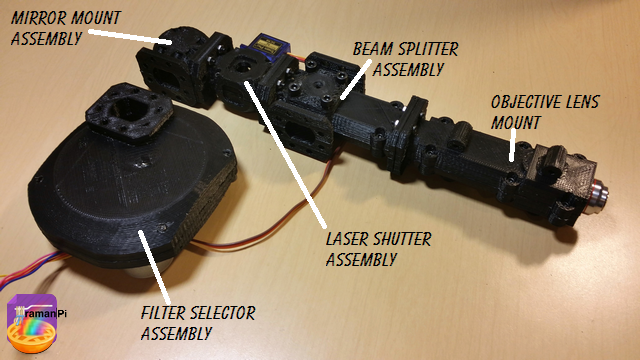
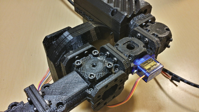
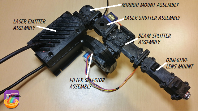
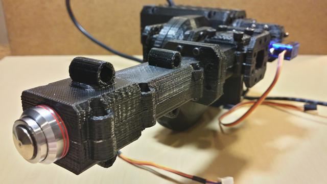
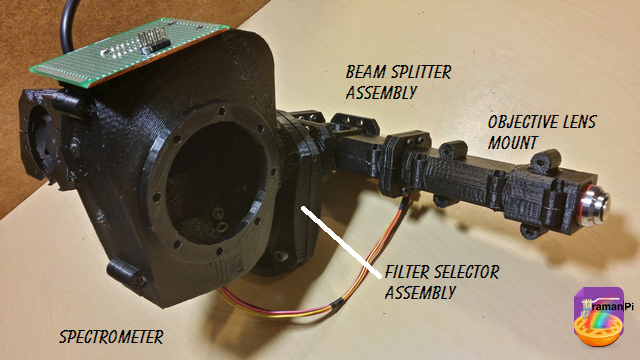
The optics section is a great success. All of the plastic parts fit perfectly, the unit is nice and solid.. The laser shines, the beam bounces from the laser and hits the splitter..half the beam goes to the objective lens and the other half goes to the filters..the selector wheel spins and chooses the filter...the beam goes through and into the spectrometer which images the spectra… I couldn’t be happier, it just needs a little alignment and calibration!
At this time, I have focused mostly on the design and construction of the electronics and optics. The software that currently exists is mostly for testing, I will be devoting as much time to the software as I have the hardware in the very near future as the hardware is getting very close to being complete!
Overall, this has been a terrific learning experience. Hackaday has been just great in its efforts and encouraging participation.. I would have been building this whether the contest existed or not, but being a part of it has made the experience far richer than I had imagined it could be. Thanks to everyone who has given me so much positive feedback the past couple months!!
![]()
-
controlBoard - schematic and board information
09/26/2014 at 08:45 • 4 comments![]()
![]()
Note: This log entry is a living document. I'll be updating this post to reflect the current configuration as time goes on.. There will also be a log at the end of the post noting modifications to the log, etc..
UPDATED-----> 10.15.2014
![]()
This log entry is where I will keep current information regarding the schematic, board layout and other details about the imagingBoard electronics and firmware.. I will reference this log entry in the 'details' section of the project page.. This log entry will probably change from time to time to reflect the current status of the imagingBoard. If you're interested, it might be worth a bookmark..
The function of the controlBoard is as follows:
- Power Relay for Laser
- TTL Control for Laser
- Monitor Temperature for Laser using DS18B20 sensor
- Control L298 HBridge for Heating/Cooling of peltiers on CCD Array and Cuvette
- PID Monitor and control Cuvette temperature using DS18B20 and L298 HBridge
- Monitor current draw from peltiers on CCD Array and Cuvette using ACS712 current sensor
- Control Beam Shutter using a standard 9gram hobby servo
- Detect Laser Good (verify beam is reaching destination) using a TEMT6000 ambient light sensor
- Open and close Cuvette Tray using stepper motors driven by ULN2003, with optical end stops
- Rotate Filter Wheel Assembly to change from 522nmSP to 550nmLP filters using ULN2003
- Detect Filter Wheel Assembly position using rotary encoder
- Monitor Cuvette Holder for presence of cuvette in tray using a optical proximity sensor
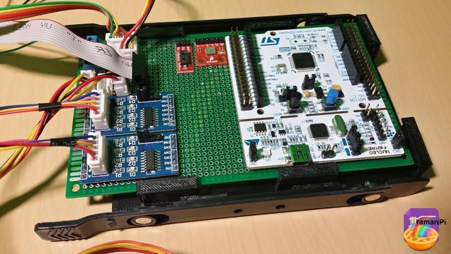
Here is what the current controlBoard looks like..
![]()
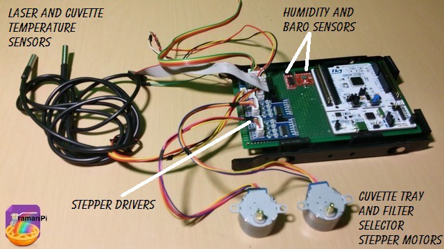
Here it is with the motors and some of the sensors...
![]()
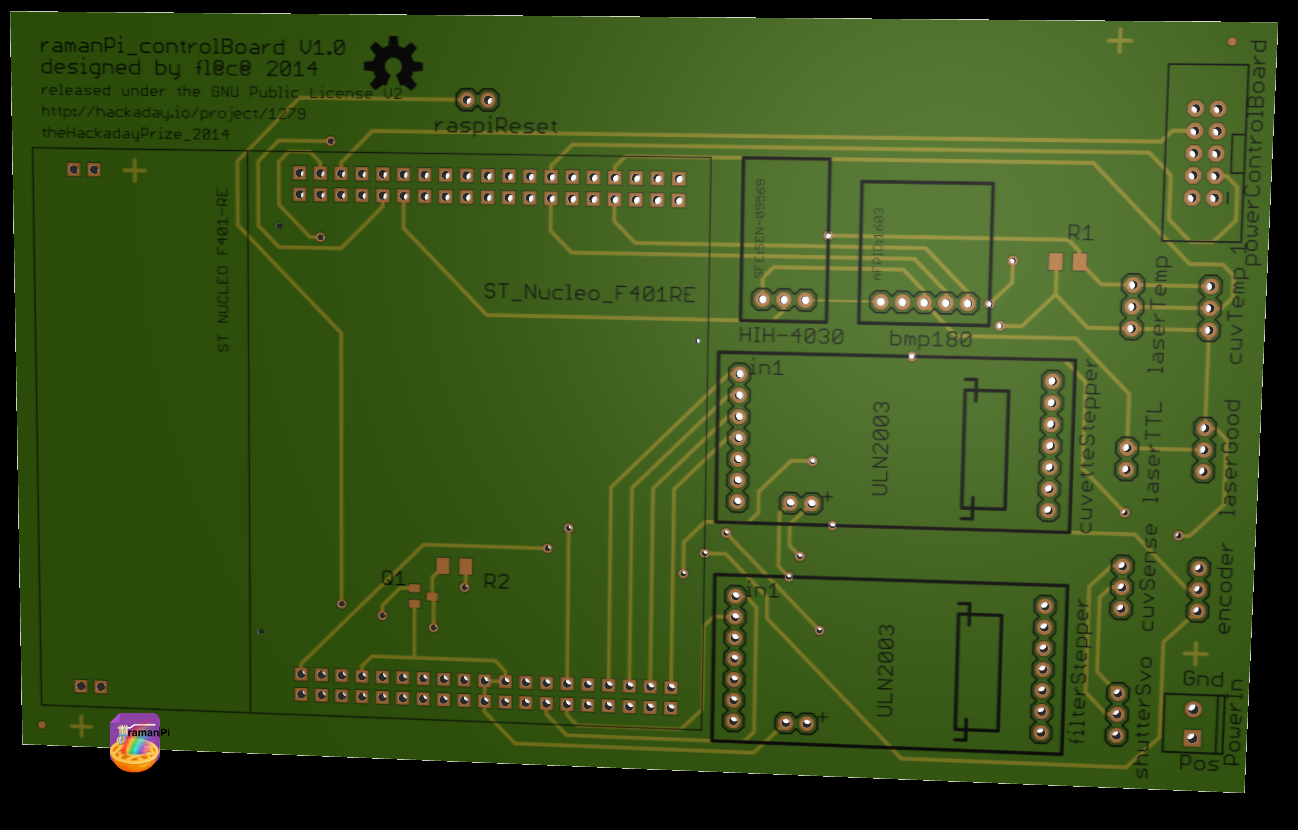
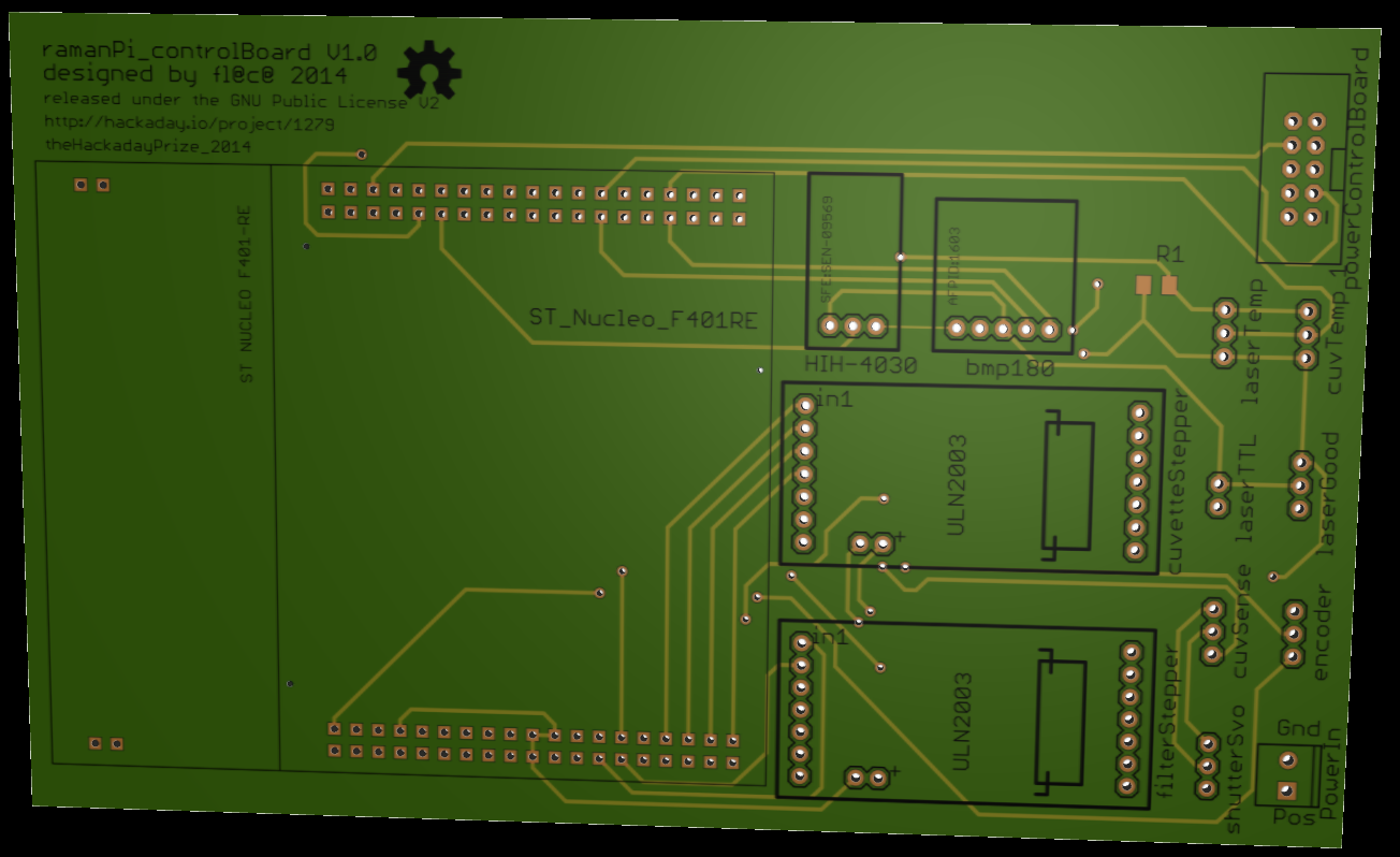
The eagle files are now in the gitHub repository, and here is a rendering of the new PCB layout...
Top
![]()
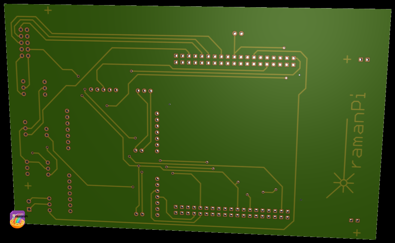
Bottom
![]()
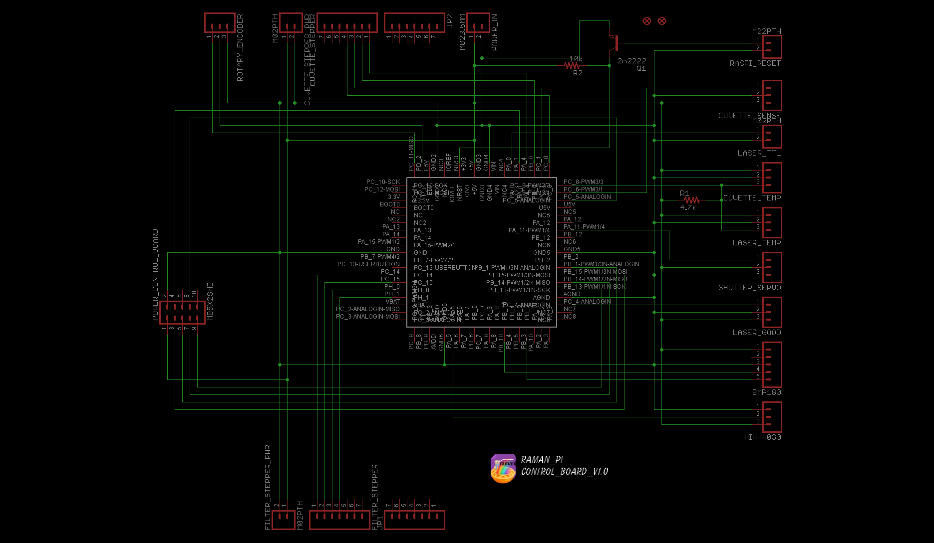
Here is the schematic..
![]()
The eagle files, and the firmware are located in the gitHub
- Hardware: gitHub repository
- Firmware: gitHub repository
The board consists of the Nucelo F401RE, two ULN2003 Stepper Motor Drivers, a BMP180 Barometric Pressure Sensor and an HIH-4030 Humidity Sensor..
![]()
UPDATE LOG:
09.17.2014 - Added living document info
10.08.2014 - Updated gitHub repository with new PCB design.. Included .studio files and images
10.08.2014 - Updated schematic and posted new PCB layout rendering
10.15.2014 - Updated schematic and posted new PCB layout rendering
-
Build Instructions: Optical Assembly
09/26/2014 at 02:17 • 3 comments![]()
![]()
Note: This log entry is a living document. I'll be updating this post to reflect the current configuration as time goes on.. There will also be a log at the end of the post noting modifications to the log, etc..
UPDATED-----> 09.25.2014
![]()
This log entry will instruct you on building the Optical Assembly..
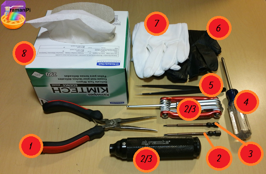
Tools Required:
- 1. Needle Nosed Pliers
- 2. 1.5mm Hex Driver
- 3. 5/64" Hex Driver
- 4. Philips Screwdriver
- 5. ESD Style Precision Tweezers
- 6. Nitrile Gloves
- 7. White Cotton Gloves
- 8. KimTech KimWipes
![]()
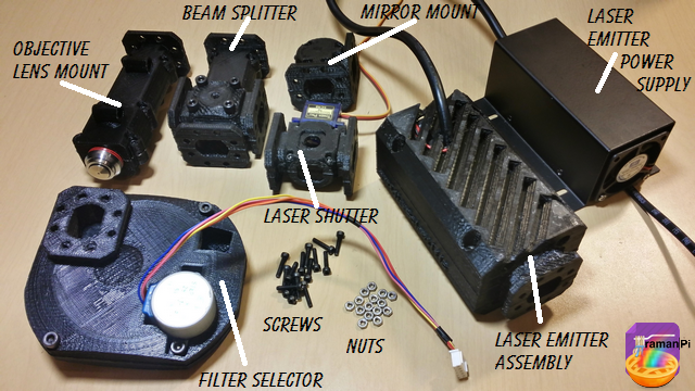
Components Required:
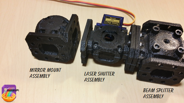
- A completed objectiveLens Mount
- A completed beamSplitter Assembly
- A completed laserShutter Assembly
- A completed mirrorMount Assembly
- A completed laserEmitter Assembly
- A completed filterSelector Assembly
- A completed Spectrometer
- (20x) M2 - 0.45 12.9mm Socket Cap Screws
- (4x) M4 16mm Socket Cap Screws
You will also have probably wanted to align your spectrometer before building this..
![]()
Steps:
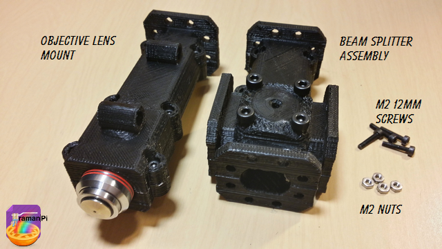
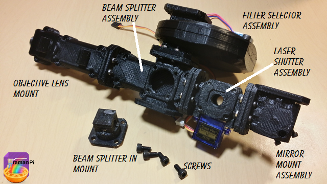
1. Get the objectiveLens Mount and the beamSplitter assembly together with four M2 screws and four M2 nuts.
![]()
2. Make sure to orient the objective lens mount and the beam splitter assembly correctly.. The long end of the beam splitter assembly connects to the objective lens mount.. All screw heads should be on the top.
![]()
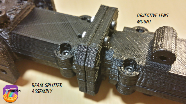
3. Place the screws in and tighten them in a graduated sequence.. Make sure to maintain as much alignment with the parts as possible.
![]()
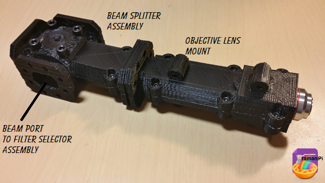
4. When you are done, it should look like this.
![]()
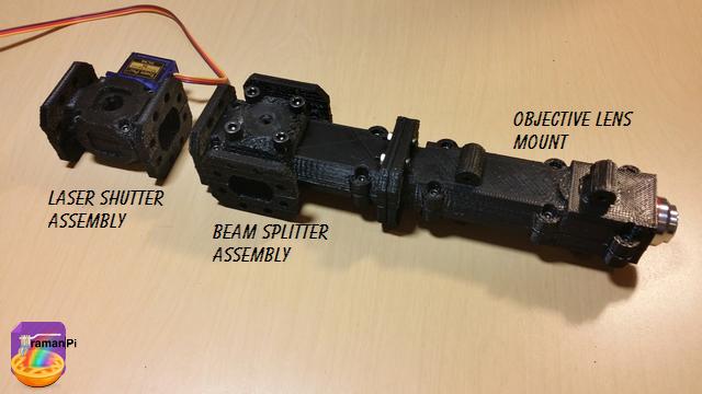
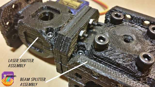
5. Now align the laser shutter assembly with the servo on the beam dump side, and screws up..
![]()
6. Tighten in a graduated sequence maintaining alignment as much as possible.
![]()
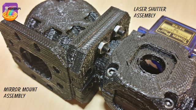
7. Align the mirror mount assembly with the laser shutter assembly with screws up and the beam entrance to the opposite side of the laser shutter servo.
![]()
8. Tighten the screws in a graduated sequence making sure to maintain alignment as much as possible.
![]()
9. It should look like this when you are done.
![]()
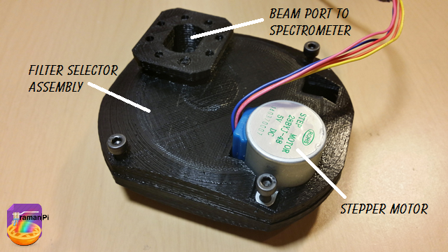
10. Get the filter selector assembly ready to attach. It will orient with the stepper motor on the opposite side of the rest of what you have so far.
![]()
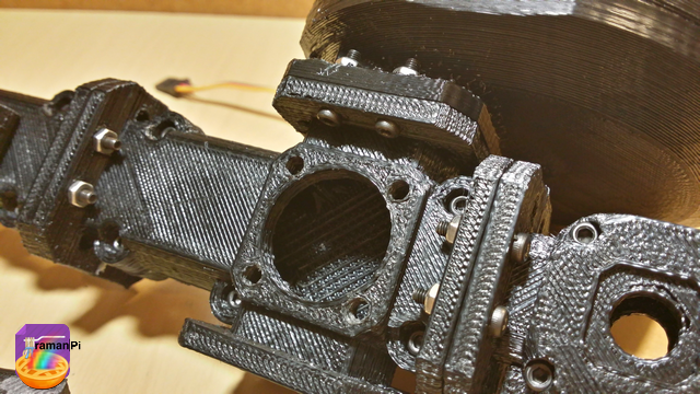
11. You will need to remove the beam splitter mount assembly from the beam splitter assembly in order to access the screw holes here.. Use nitrile gloves at minimum when handling the splitter assembly..
![]()
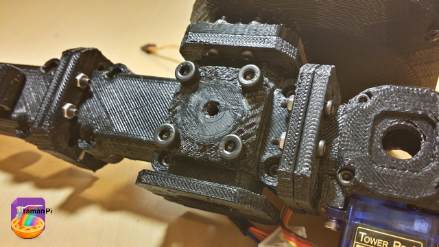
12. Carefully and in a graduated order, tighten the screws while maintaining alignment as much as possible.
![]()
13. Replace the beam splitter mount assembly back into the beam splitter assembly..
![]()
![]()
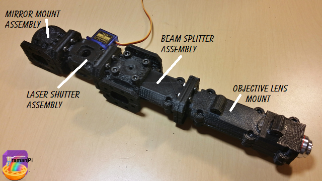
14. It should be looking pretty good so far..!
![]()
15. Align the laser emitter assembly screws up and mated to the mirror mount assembly.. The screws go directly into the flange on the laser emitter assembly... Do not over-tighten them!
![]()
![]()
16. It should look like this when you're done.
![]()
That completes the raman section of this build!! Wow!
![]()
17. Now we are ready to attach the Spectrometer! The spectrometer aligns like this... Board up, and access port to the front.
![]()
18. You will be screwing the M4 screws in from through the access port and the inside of the Spectrometer.. It's a bit of a challenge, use a 90 angle allen key if possible.
![]()
19. When that is done, place the access port cover back on the spectrometer!
![]()
20. And when you are done, you will have completed the Optics Assembly and it should look like this!
![]()
![]()
![]()
Congratulations!!
Set aside and move to next build!
You can close this tab or return to the build instructions here!
![]()
UPDATE LOG:
09.23.2014 - New Entry
-
Build Instructions: Filter Selector Assembly
09/25/2014 at 23:59 • 9 comments![]()
![]()
Note: This log entry is a living document. I'll be updating this post to reflect the current configuration as time goes on.. There will also be a log at the end of the post noting modifications to the log, etc..
UPDATED-----> 09.25.2014
![]()
This log entry will instruct you on building the Objective Lens Mount..
Tools Required:
- 1. Needle Nosed Pliers
- 2. 1.5mm Hex Driver
- 3. 5/64" Hex Driver
- 4. Philips Screwdriver
- 5. ESD Style Precision Tweezers
- 6. Nitrile Gloves
- 7. White Cotton Gloves
- 8. KimTech KimWipes
![]()
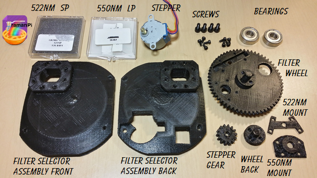
Components Required:
- Printed versions of the following 3D Printed Objects from the gitHub repository:
- mechanical_device_filterSelectorAssembly_front
- mechanical_device_filterSelectorAssembly_back
- mechanical_device_filterSelectorAssembly_filterWheel
- mechanical_device_filterSelectorAssembly_centerHub_Back
- mechanical_device_filterSelectorAssembly_522nmSP_cover
- mechanical_device_filterSelectorAssembly_550nmSP_cover
- (1x) Optical Filter 522SP, 5mm X 40mm X 2.4mm thick
- (1x) Optical Filter, 550LP, 10.1mm dia. X 3mm thick
- (1x) DC 5V Stepper Motor
- (4x) M4 - 16mm Socket Cap Screws
- (8x) M2 - 12mm Socket Cap Screws
![]()
Steps:
1. Print and clean up the plastic parts. Be sure to use the 3D printed part guidelines. All spurs and supports need to be cleaned as much as possible.
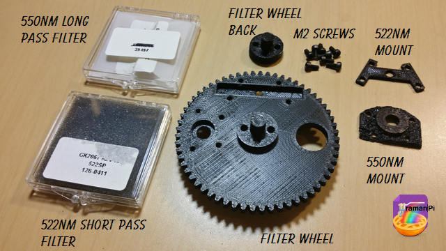
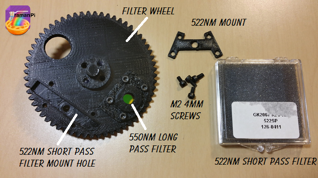
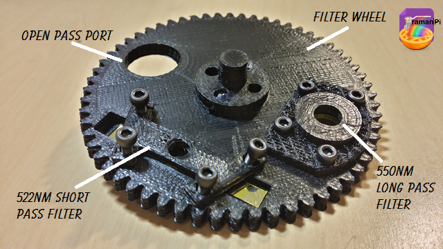
2. Gather the 550nmLP filter, the 522nmSP filter, the filter wheel, the filter wheel back, 8 of the M2 4mm screws, the 522nm mount cover, and the 550nm mount cover..
![]()
NOTE: WEAR THE NITRILE GLOVES AND THE COTTON GLOVES FOR THIS STEP. USE THE PRECISION TWEEZERS TO HANDLE THE 550NM LP FILTER. TAKE SPECIAL CARE NOT TO TOUCH THE SURFACE OF THE FILTER!!
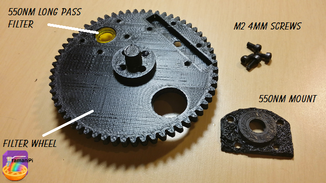
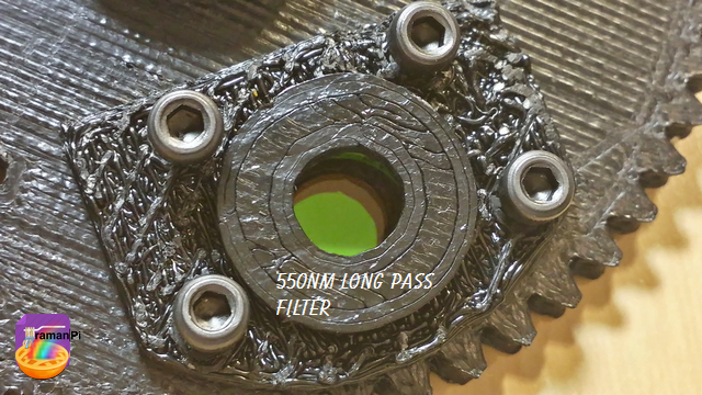
3. Take the 550nm Long Pass FIlter, notice around the edge there is an arrow.. That arrow goes toward the back of the filter wheel.. You are looking at the front of the wheel here...Place the filter in the 550nm Long Pass Filter Mounting Hole..
![]()
4. Gently place the 550NM mount cover over the filter, and insert screws..
![]()
NOTE: You can remove the cotton gloves, but I recommend keeping the nitrile gloves on.
5. Gently tighten the screws..Do not over-tighten.
![]()
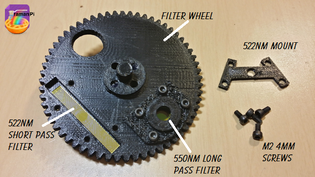
6. Gather the 522NM Short Pass Filter, four M2 4mm screws, the 522nm mount and the filter wheel with the 550nm Long Pass Filter installed.
![]()
NOTE: PUT THE COTTON GLOVES BACK ON
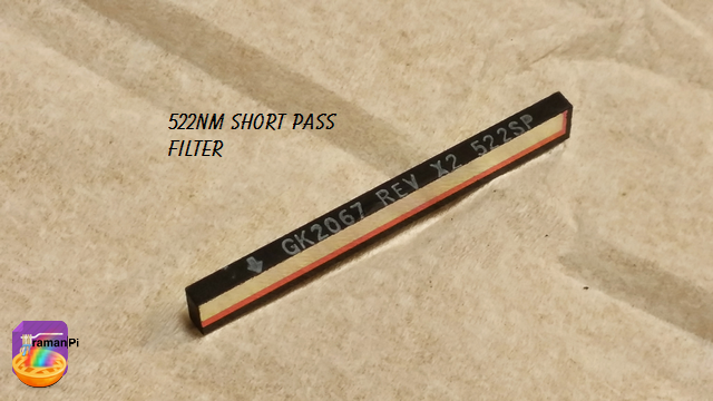
7. Notice the arrow on the 522NM Short Pass Filter.. This arrow also points to the back of the filter wheel.
![]()
8. Gently place the 522NM Short Pass Filter into the filter wheel mount. (Arrow points back!)
![]()
NOTE: You can remove the cotton gloves, but I'd still recommend keeping the nitrile gloves on..
9. Gently place the 522NM mount over the 522NM Short Pass FIlter, and gently screw it in place.
![]()
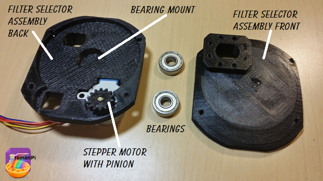
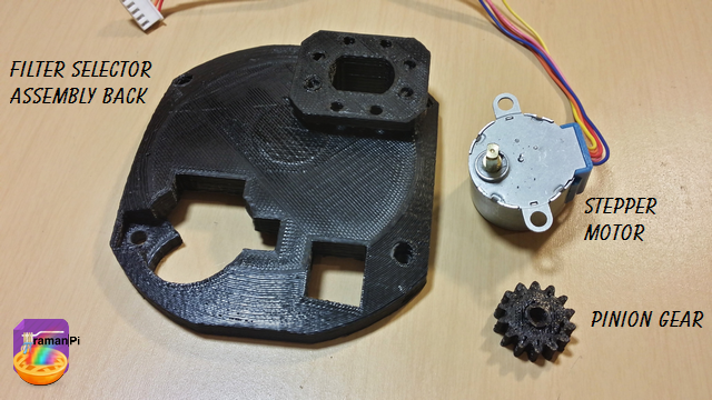
10. Gather the Filter Selector Assembly Back, the stepper motor and its pinion gear.
![]()
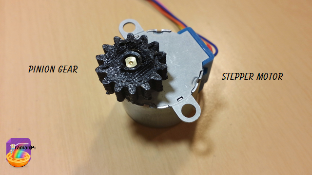
11. Attach the pinion gear to the stepper motor.
![]()
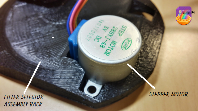
12. Insert the stepper motor into the Filter Selector Assembly Back..
![]()
13. Make sure it is seated properly..
![]() 14. Grab the two 608Z bearings, the Filter Selector Assembly Front and the back you just finished.
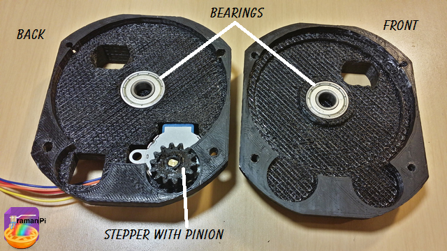
14. Grab the two 608Z bearings, the Filter Selector Assembly Front and the back you just finished.![]()
15. Gently insert the bearings into the bearing mounts..
![]()
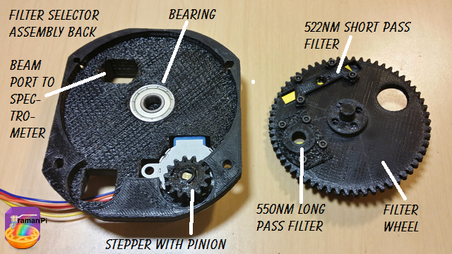
16. Take the Filter Selector Assembly back with the stepper, pinion and bearing...and the filter wheel with the filters..
![]()
17. Place the filter wheel into the assembly.. The filters should be facing the front.. Don't worry about alignment at this point, we will cover that in a later configuration section.
![]()
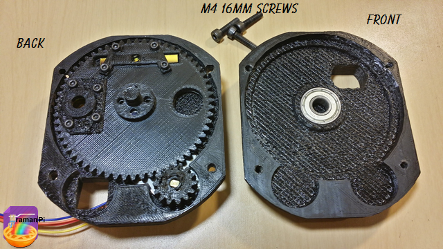
18. Take the back of the assembly, the front and the M4 16mm screws..
![]()
19. Place the front onto the back of the assembly very carefully, and screw it together....
![]()
That completes this section! Congratulations!!
Set aside and move to next build!
You can close this tab or return to the build instructions here!
![]()
UPDATE LOG:
09.23.2014 - New Entry
-
Build Instructions: Laser Emitter Assembly
09/25/2014 at 22:47 • 8 comments![]()
![]()
Note: This log entry is a living document. I'll be updating this post to reflect the current configuration as time goes on.. There will also be a log at the end of the post noting modifications to the log, etc..
UPDATED-----> 09.25.2014
![]()
This log entry will instruct you on building the Laser Emitter Assembly..
Tools Required:
- 1. Needle Nosed Pliers
- 2. 1.5mm Hex Driver
- 3. 5/64" Hex Driver
- 4. Philips Screwdriver
- 5. ESD Style Precision Tweezers
- 6. Nitrile Gloves
- 7. White Cotton Gloves
- 8. KimTech KimWipes
![]()
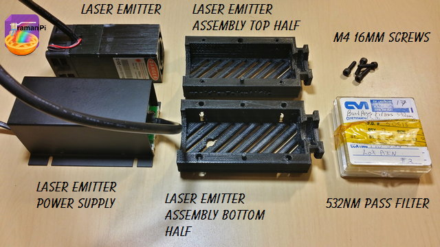
Components Required:
- Printed versions of the following 3D Printed Objects from the gitHub repository:
- (1x) 532nm 150mw Green Laser Module with Thermoelectric Cooling and TTL Modulated
- (1x) CVI 532nm bandpass interference filter one inch dia. # F10-532-4
- (4x) M4 - 16mm Socket Cap Screws
![]()
Steps:
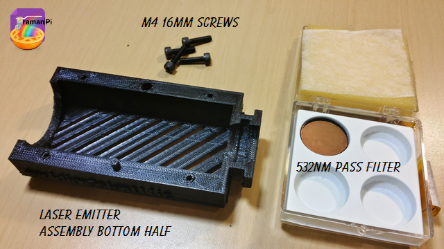
1. Print and clean up the plastic parts. Be sure to use the 3D printed part guidelines. All spurs and supports need to be cleaned as much as possible.
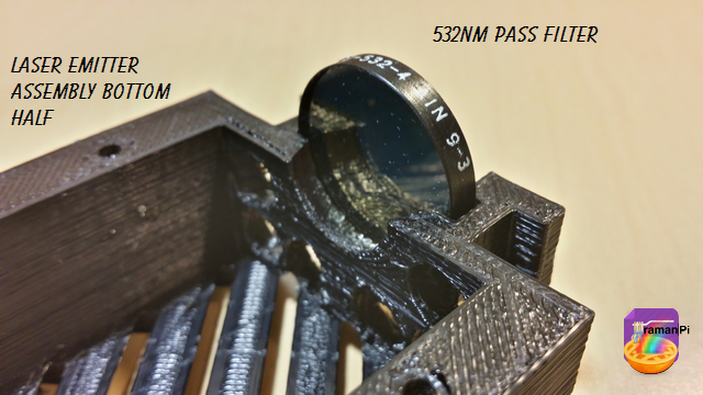
2. Grab the bottom half of the laser emitter assembly and the 532nm Pass Filter.
![]()
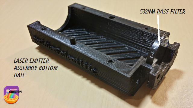
3. Make sure you are wearing the nitrile gloves and a pair of the white gloves over them and place the CVI 532nm bandpass interference filter one inch dia. # F10-532-4 into the bottom half of the laserEmitter Assembly and set aside for the moment..
![]()
NOTE: Make sure the surface mirror side is on the outside of the assembly!
![]()
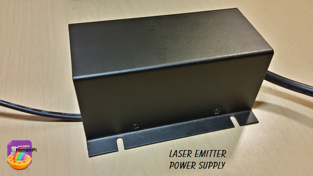
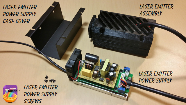
4. Grab the laser emitter power supply.
![]()
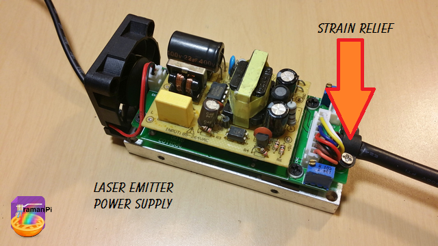
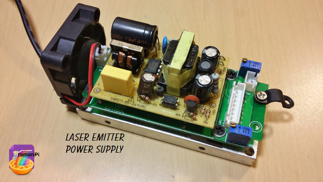
5. Remove the screws from the cover and remove the cover. Then remove the strain relief screws.
![]()
6. Once that is done, remove the laser emitter power cable.
![]()
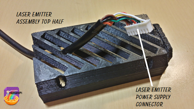
7. Grab the top half of the laser emitter assembly and pass the connector end of the laser emitter power cable through the small hole towards the back from the inside to the outside..
![]()
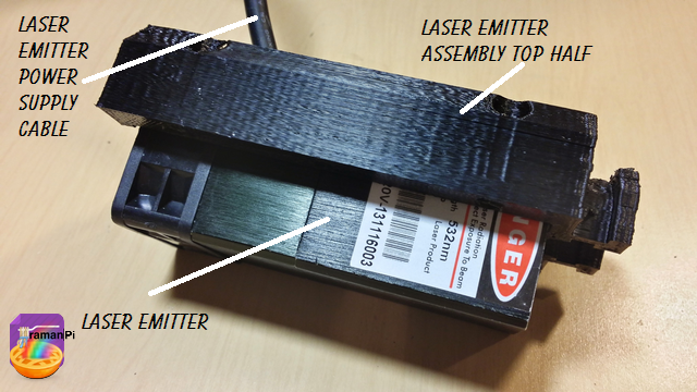
8. Slide the laser emitter assembly top half down the cable and fit the emitter into the assembly.
![]()
9. Grab the bottom half of the assembly, gently place in on the laser emitter and make sure not to scratch the pass filter! Then place the 4 M4 16mm screws in the screw holes.
![]()
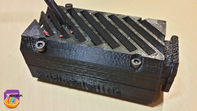
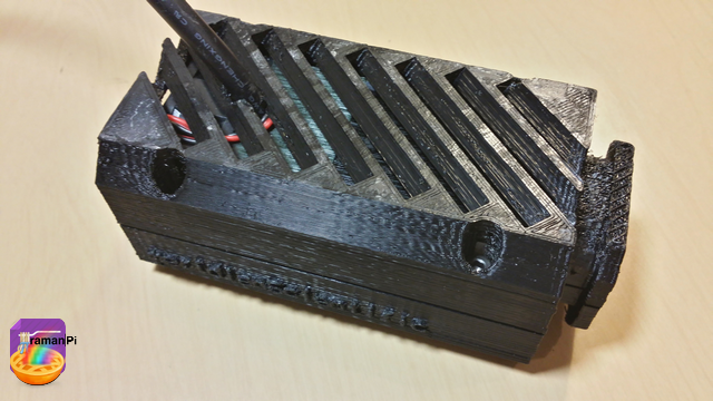
10. Tighten the screws.
![]()
11. Grab the laser emitter power supply, the cover and its screws..
![]()
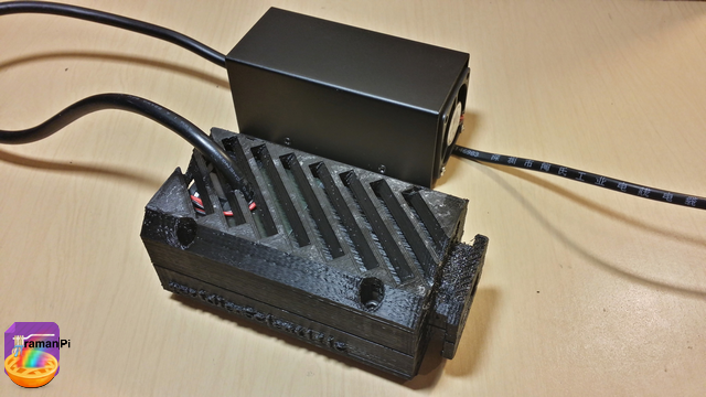
12. Place the cover back on the power supply and screw it on.
![]()
And that completes this section! Congratulations!
Set aside and move to next build!
You can close this tab or return to the build instructions here!
![]()
UPDATE LOG:
09.25.2014 - New Entry
ramanPi - Raman Spectrometer
The open source 3D Printable Raman Spectrometer using a RaspberryPi and easy to find off the shelf components..


 14. Grab the two 608Z bearings, the Filter Selector Assembly Front and the back you just finished.