fl@C@
fl@C@-
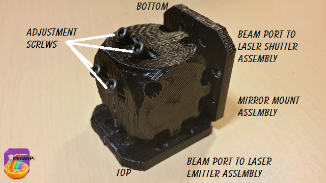
Build Instructions: Mirror Mount Assembly
09/25/2014 at 22:01 • 0 comments![]()
![]()
Note: This log entry is a living document. I'll be updating this post to reflect the current configuration as time goes on.. There will also be a log at the end of the post noting modifications to the log, etc..
UPDATED-----> 09.25.2014
![]()
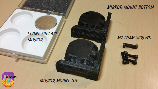
This log entry will instruct you on building the Mirror Mount Assembly.
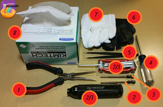
Tools Required:
- 1. Needle Nosed Pliers
- 2. 1.5mm Hex Driver
- 3. 5/64" Hex Driver
- 4. Philips Screwdriver
- 5. ESD Style Precision Tweezers
- 6. Nitrile Gloves
- 7. White Cotton Gloves
- 8. KimTech KimWipes
![]()
Components Required:
- Printed versions of the following 3D Printed Objects from the gitHub repository:
- (1x) 100x Microscope Objective Lens
- (6x) M2 - 0.45 12.9mm Socket Cap Screws
![]()
Steps:
1. Print and clean up the plastic parts. Be sure to use the 3D printed part guidelines. All spurs and supports need to be cleaned as much as possible.
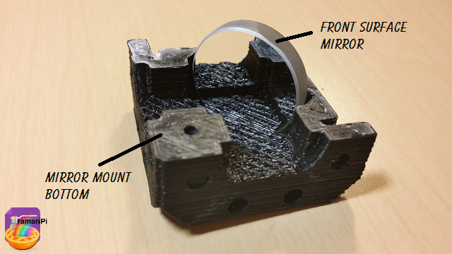
2. Place the 1 Newport Pyrex First Surface Laser Mirror 1" Model# 10R08 ER1 into the slot on the bottom half of the mirror mount.
![]()
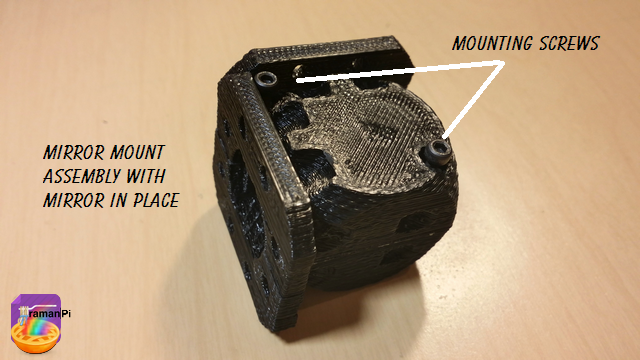
2. Place the top and bottom halves together, and place the mounting screws in.. Tighten the back screw and then the front.. Don't over-tighten!
![]()
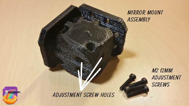
3. Grab four of the M2 12mm adjustment screws..
![]()
3. Insert and lightly tighten the four adjustment screws on the back of the assembly... Don't worry about alignment at this point.. That will be covered later in the system alignment series..
![]()
That completes the construction of the mirrorMount Assembly! Set aside and move to next build!
You can close this tab or return to the build instructions here!
![]()
UPDATE LOG:
09.23.2014 - New Entry
-
Build Instructions: Laser Shutter Assembly
09/25/2014 at 21:26 • 0 comments![]()
![]()
Note: This log entry is a living document. I'll be updating this post to reflect the current configuration as time goes on.. There will also be a log at the end of the post noting modifications to the log, etc..
UPDATED-----> 09.25.2014
![]()
This log entry will instruct you on building the laserShutter Assembly..
Tools Required:
- 1. Needle Nosed Pliers
- 2. 1.5mm Hex Driver
- 3. 5/64" Hex Driver
- 4. Philips Screwdriver
- 5. ESD Style Precision Tweezers
- 6. Nitrile Gloves
- 7. White Cotton Gloves
- 8. KimTech KimWipes
![]()
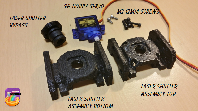
Components Required:
- Printed versions of the following 3D Printed Objects from the gitHub repository:
- (1x) optics_module_laserShutter_bottom
- (1x) optics_module_laserShutter_top
- (1x) optics_module_shutter_bypass
- (1x) 9g Hobby Servo
- (6x) M2 - 0.45 12.9mm Socket Cap Screws
![]()
Steps:
1. Print and clean up the plastic parts. Be sure to use the 3D printed part guidelines. All spurs and supports need to be cleaned as much as possible.
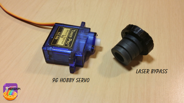
2. Grab the 9g Hobby Servo and the Laser Shutter Bypass and attach the Shutter Bypass to the servo.
![]()
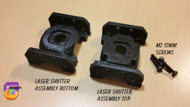
3. Take the top and bottom halves of the laserShutter Assembly and four of the M2 12mm Screws.
![]()
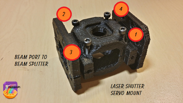
4. Place the screws in the screw holes and tighten them in the following order.
![]()
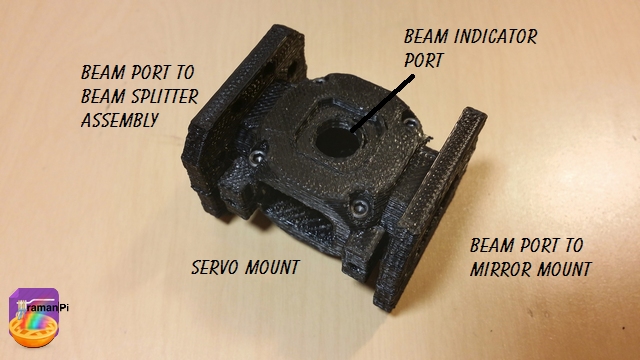
5. It should look like this. Make note the servo mount orientation...The servo head goes to the left of the mount from the perspective below..You can see the hole extends further in that direction.
![]()
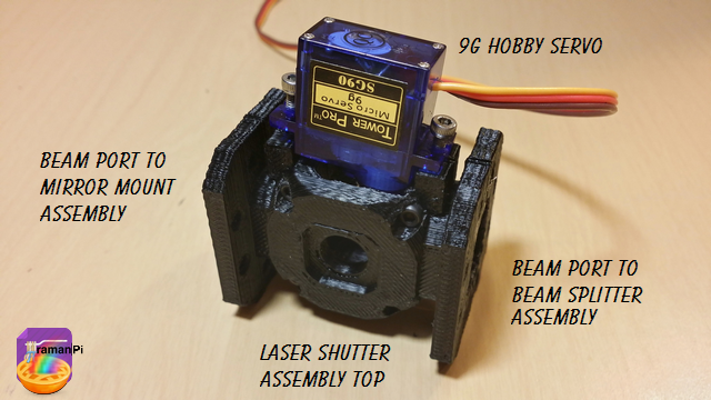
6. Place the servo and bypass into the servo mount.
![]()
That completes this part!
![]()
Set aside and move to next build!
You can close this tab or return to the build instructions here!
![]()
UPDATE LOG:
09.25.2014 - New Entry
-
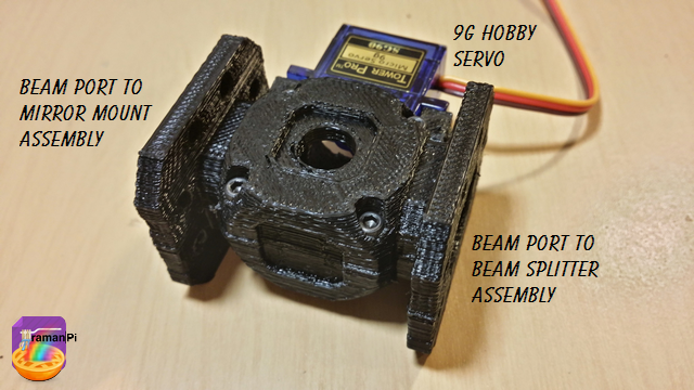
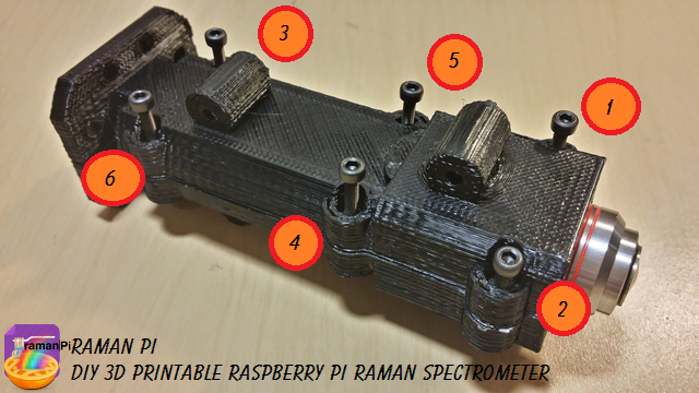
Build Instructions: Beam Splitter Assembly
09/25/2014 at 13:26 • 4 comments![]()
![]()
Note: This log entry is a living document. I'll be updating this post to reflect the current configuration as time goes on.. There will also be a log at the end of the post noting modifications to the log, etc..
UPDATED-----> 09.25.2014
![]()
This log entry will instruct you on building the beamSplitter Assembly..
Tools Required:
- 1. Needle Nosed Pliers
- 2. 1.5mm Hex Driver
- 3. 5/64" Hex Driver
- 4. Philips Screwdriver
- 5. ESD Style Precision Tweezers
- 6. Nitrile Gloves
- 7. White Cotton Gloves
- 8. KimTech KimWipes
![]()
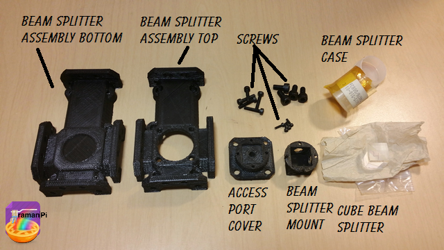
Components Required:
- Printed versions of the following 3D Printed Objects from the gitHub repository:
- (1x) Cube beam splitter 12.5mm for 532nm
- (5x) M2 - 0.45 12.9mm Socket Cap Screws
- (4x) M4 - 16mm Socket Cap Screws
- (4x) M1.6 - 4mm Socket Cap Screws
![]()
Steps:
1. Print and clean up the plastic parts. Be sure to use the 3D printed part guidelines. All spurs and supports need to be cleaned as much as possible.
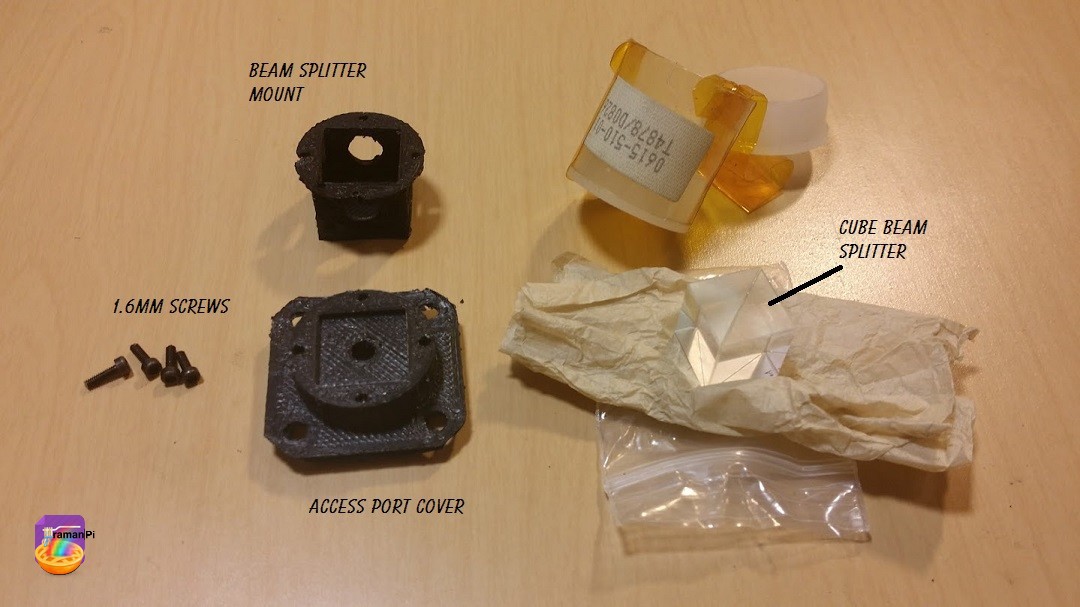
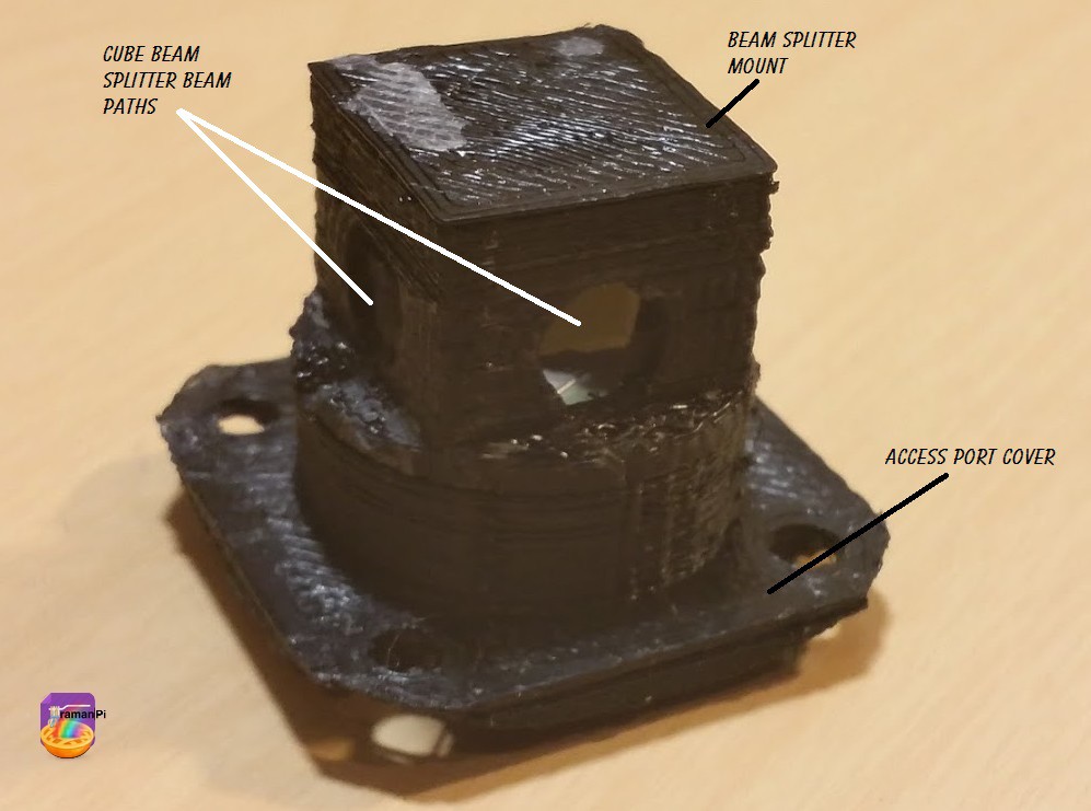
2. Grab the beam splitter, the splitter mount, the access port cover and the 1.6mm screws..
![]()
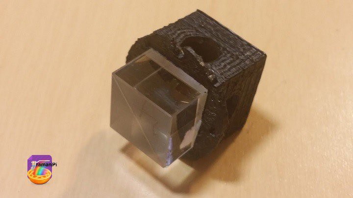
3. While wearing a pair of the nitrile gloves inside a pair of the white cotton gloves, place the cube beam splitter inside the beam splitter mount. Take note of the orientation!
![]()
4. You can remove the cotton gloves at this point, but I'd recommend leaving the nitrile gloves on.. Place the beam splitter and mount on bottom side of the access port cover... Make sure you orient the splitter so the angled line is going from the top left to the bottom right from the bottom perspective.
![]()
5. Insert 1.6mm screws into mounting holes and tighten down.. Then set aside.
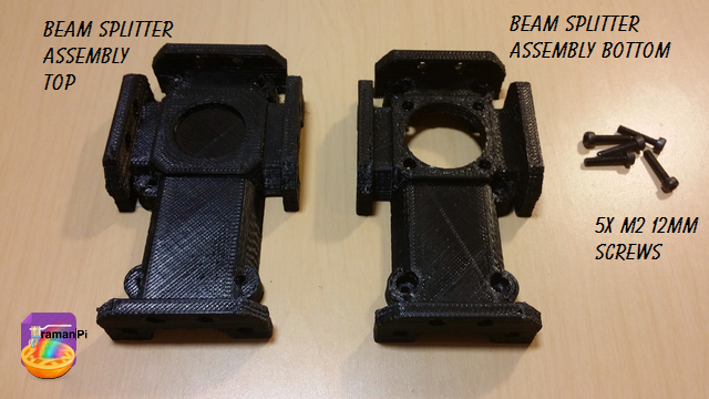
6. Grab the top and bottom half of the beam splitter assembly and 5 of the M2 screws..
![]()
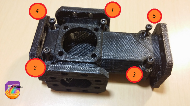
7. Set the top half on the bottom half and place the screws into the holes, then tighten them in the following order.
![]()
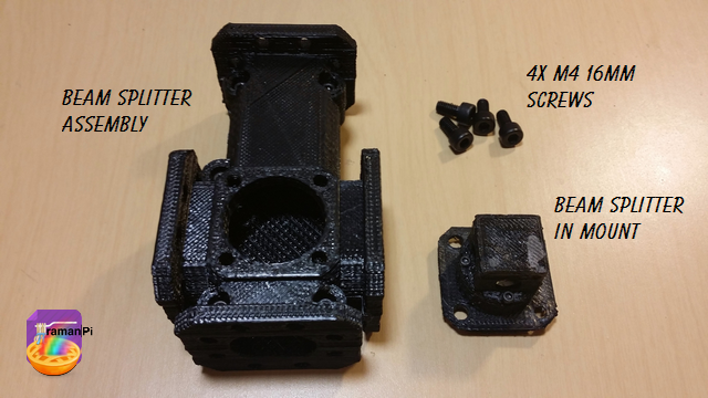
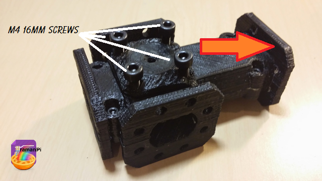
8. Gather 4 of the M4 screws, the beam splitter in the mount attached to the access port cover.
![]()
9. Place the beam splitter in its mount attached to the access port cover into the access port making not of orientation. The arrow should be pointing towards the long end of the beam splitter assembly. Place the screws into the holes.
![]()
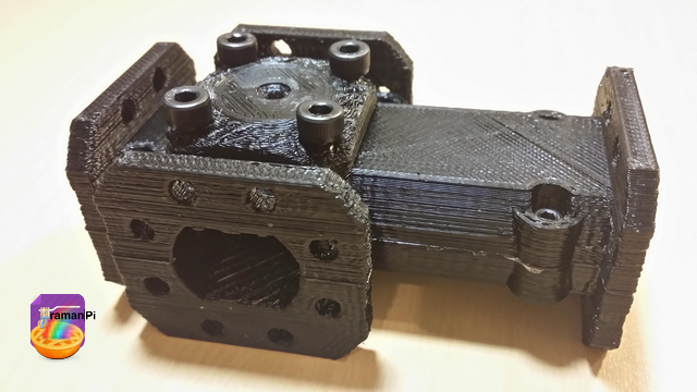
10. Tighten the screws.
![]()
That completes the beamSplitter Assembly construction!
Set aside and move to next build!
You can close this tab or return to the build instructions here!
![]()
UPDATE LOG:
09.25.2014 - New Entry
-
Build Instructions: Objective Lens Mount
09/23/2014 at 10:41 • 7 comments![]()
![]()
Note: This log entry is a living document. I'll be updating this post to reflect the current configuration as time goes on.. There will also be a log at the end of the post noting modifications to the log, etc..
UPDATED-----> 09.25.2014
![]()
This log entry will instruct you on building the Objective Lens Mount..
Tools Required:
- 1. Needle Nosed Pliers
- 2. 1.5mm Hex Driver
- 3. 5/64" Hex Driver
- 4. Philips Screwdriver
- 5. ESD Style Precision Tweezers
- 6. Nitrile Gloves
- 7. White Cotton Gloves
- 8. KimTech KimWipes
![]()
Components Required:
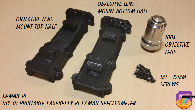
- Printed versions of the following 3D Printed Objects from the gitHub repository:
- (1x) 100x Microscope Objective Lens
- (6x) M2 - 0.45 12.9mm Socket Cap Screws
![]()
Steps:
1. Print and clean up the plastic parts. Be sure to use the 3D printed part guidelines. All spurs and supports need to be cleaned as much as possible.
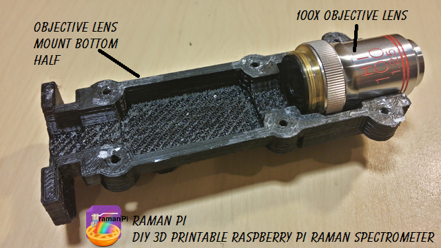
2. Place Microscope Objective Lens in the lower half of the assembly on the objective lens end...
![]()
3. Place the screws in the screw holes and tighten in the following order...
![]()
That completes this part!
![]()
Set aside and move to next build!
You can close this tab or return to the build instructions here!
![]()
UPDATE LOG:
09.23.2014 - New Logo
09.25.2014 - Added Required Tools
09.25.2014 - New Photos
-
beamSplitter and filterWheel
09/19/2014 at 13:39 • 0 comments![]()
I've been working feverishly toward getting raman spectra for the past couple weeks... I updated and have gotten the spectrometer to a pretty good point...and now, tonight have gotten the kinks worked out of the filter wheel assembly and the beam splitter assembly..!
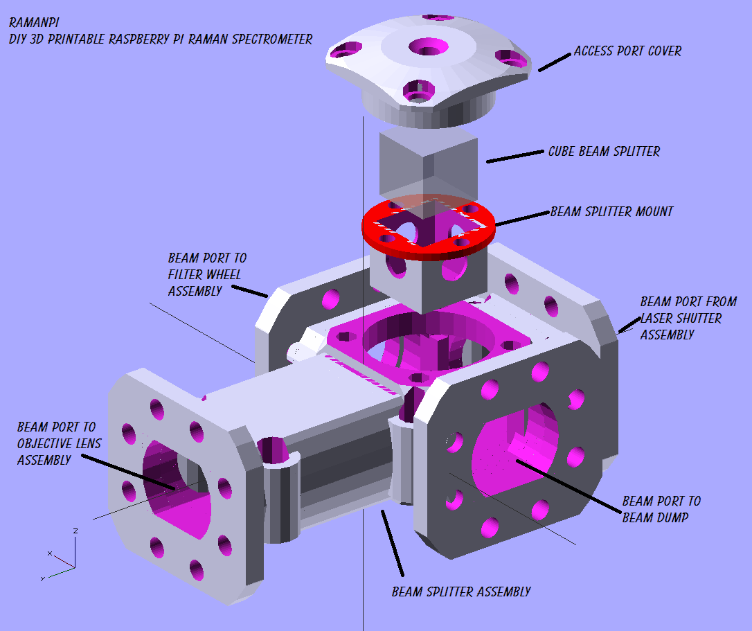
The beam splitter assembly now has a access port cover to which the beam splitter mount attaches.. The splitter is captured in a small mount that bolts to the bottom of the access port cover.. It allows the beam splitter to be mounted and then fit into the splitter assembly where you can make any minor adjustments needed..
Here's an exploded view of the beam splitter assembly....
![]()
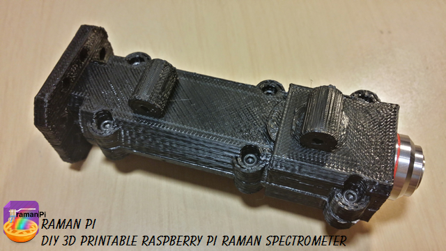
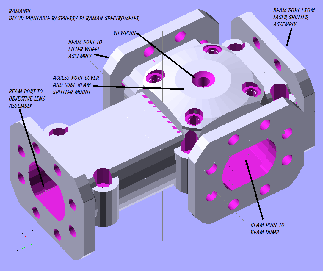
And here is an assembled view...
![]()
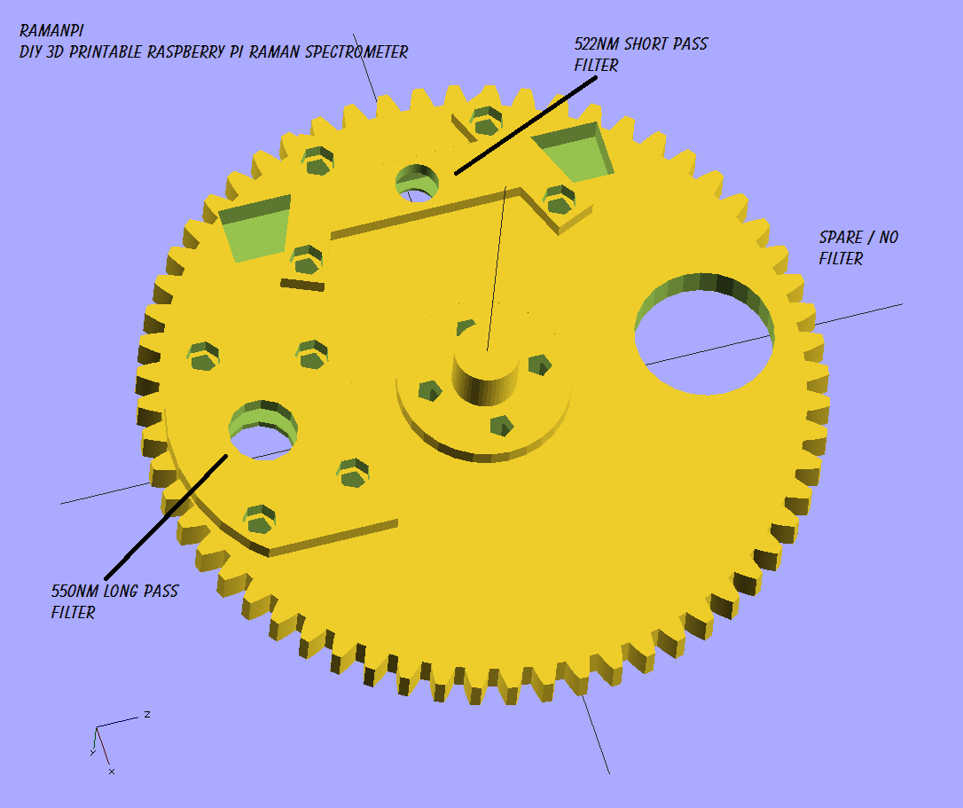
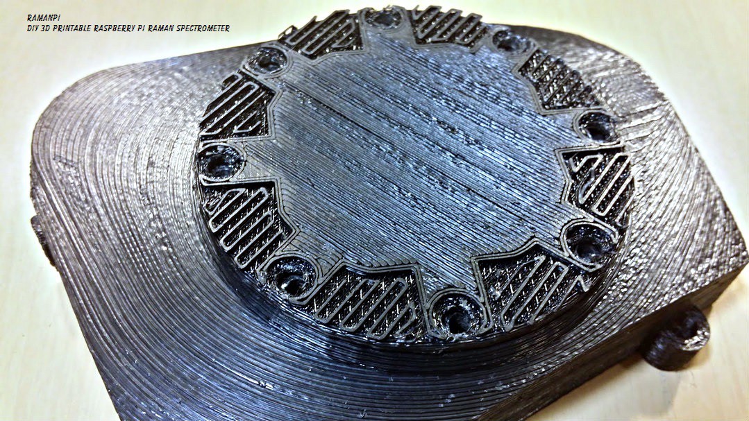
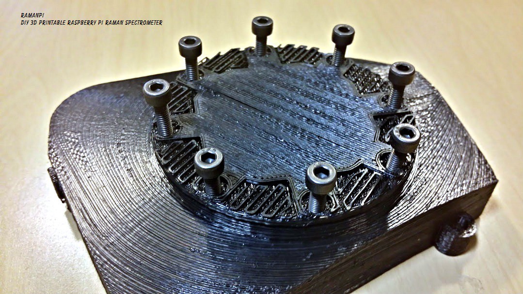
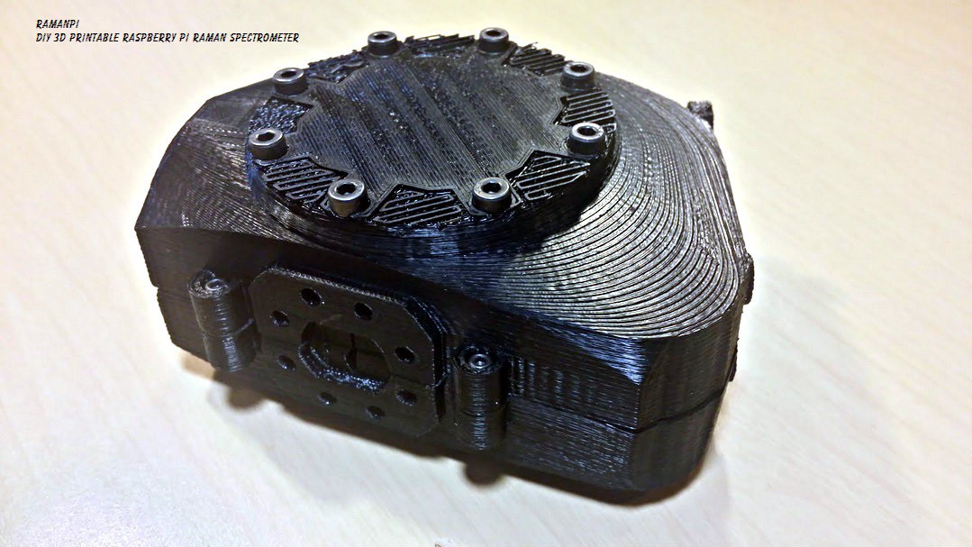
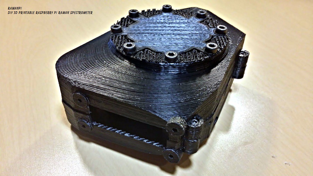
The filter wheel only needed the wheel itself and the mounting brackets updated...
Here's the new wheel with brackets...
![]()
The wheel and brackets just finished printing and I'll get images up as soon as possible... The beam splitter is just starting its print.. Hopefully I can get pictures of that up tomorrow! Once these are done and assembled, and the splitter and filters are mounted... I should be able to start some testing to get raman spectra!
![]()
![]()
-
Spectrometer Alignment
09/18/2014 at 05:51 • 3 comments![]()
![]()
Note: This log entry is a living document. I'll be updating this post to reflect the current configuration as time goes on.. There will also be a log at the end of the post noting modifications to the log, etc..
UPDATED-----> 09.23.2014
![]()
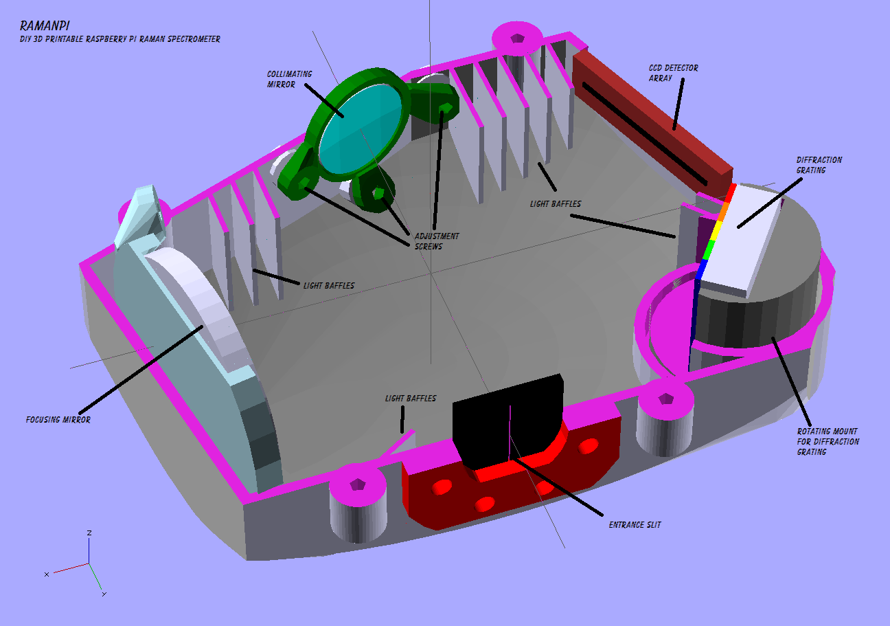
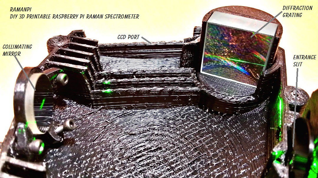
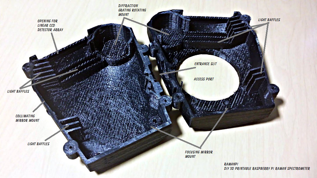
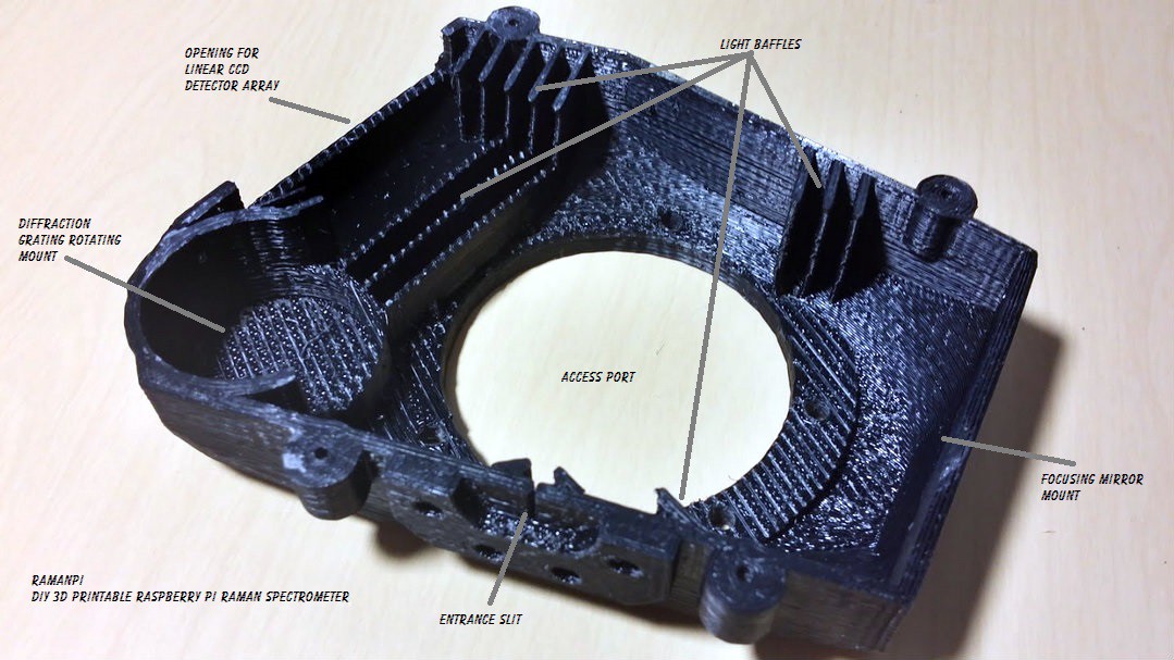
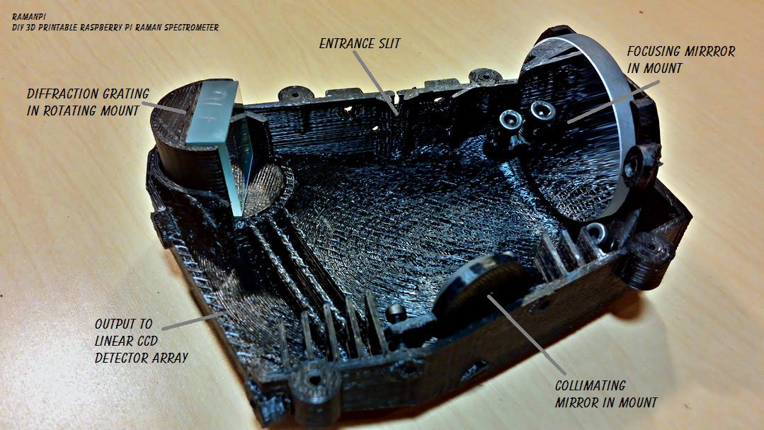
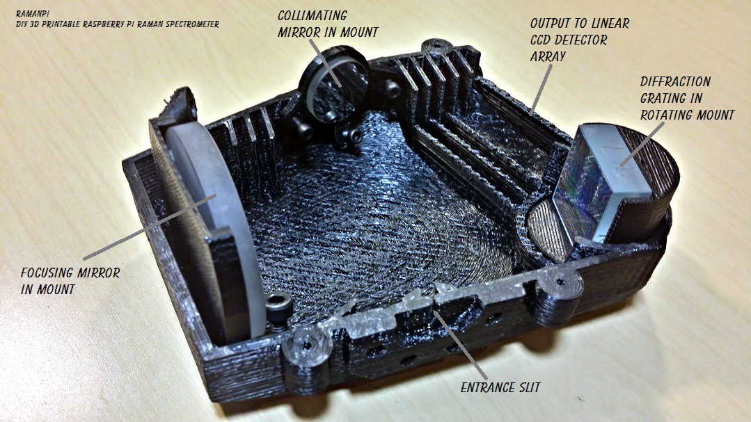
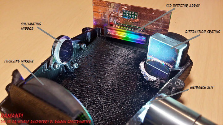
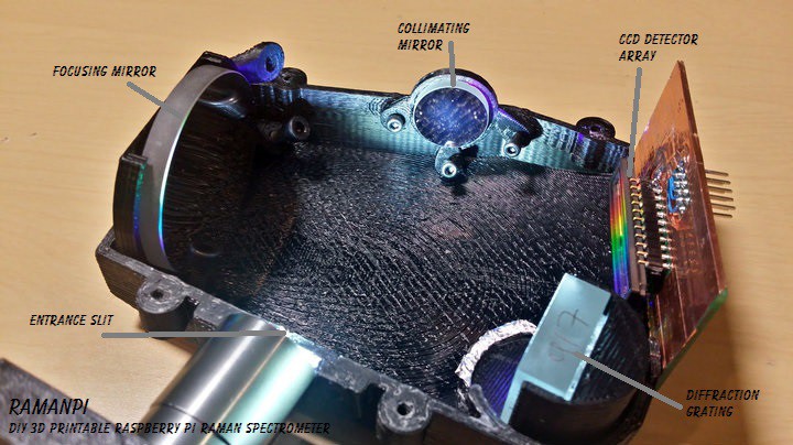
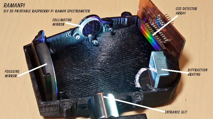
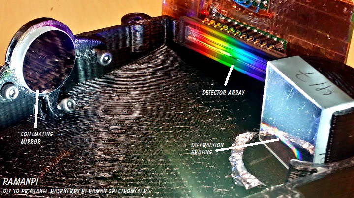
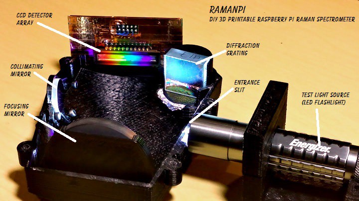
Once you've assembled your spectrometer, you'll need to align the optics so the light coming in through the entrance slit makes it to it's destination....the detector array... The light will enter through the entrance slit, hit the collimating mirror where it is directed in an orderly path to the diffraction grating...at this point, the light will be split into the colors it's composed of....that light is reflected off the grating onto the focusing or 'imaging' mirror...from there it is focused onto the detector array where it's read out to the microcontroller and passed to the raspberryPi for processing...and so on..
![]()
To align your spectrometer, you will have had to assemble it following the instructions in this post.. Which means you'll have all the parts necessary and are ready to go..
Alignment is pretty straight forward..There are some precautions to take, and you'll need a couple tools.. You need a 2mm and 4mm allen wrench or driver...I recommend the driver as the bent wrench poses a hazard to scratching your optics if you're not extremely careful..
To do this alignment procedure, I recommend you have a laser pointer and have printed this test stand I designed specifically for this purpose... You'll also need this part x2 which is the top bridge for the mount..
![]()
So, let's get started..
FIRST AND FOREMOST---SAFETY!!! WEAR LASER PROTECTION WHILE ALIGNING ANYTHING WITH LASERS!!! 5MW is still enough to cause damage.. Just let it be known I told you so...!!
For now, it's easiest if we start with the top half of the spectrometer removed.. This will make life easier when trying to access the adjustment screws, etc.. The access port gives a good perspective, and allows for minor maintenance but I'd recommend against starting your alignment through the port..
You should be looking at something like this...
![]()
First, lets start by attaching the test stand... You can attach the test stand to the side of the spectrometer at the entrance slit flange using a few M4 hex screws..The same type as the access cover lid on the spectrometer. The test stand also has a receptacle for a vial which you can use later for other fun stuff.. :)
After attaching, you should be seeing something like this...
![]()
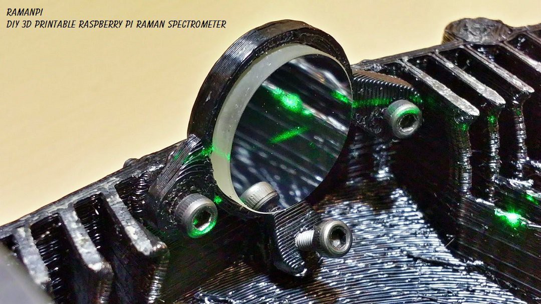
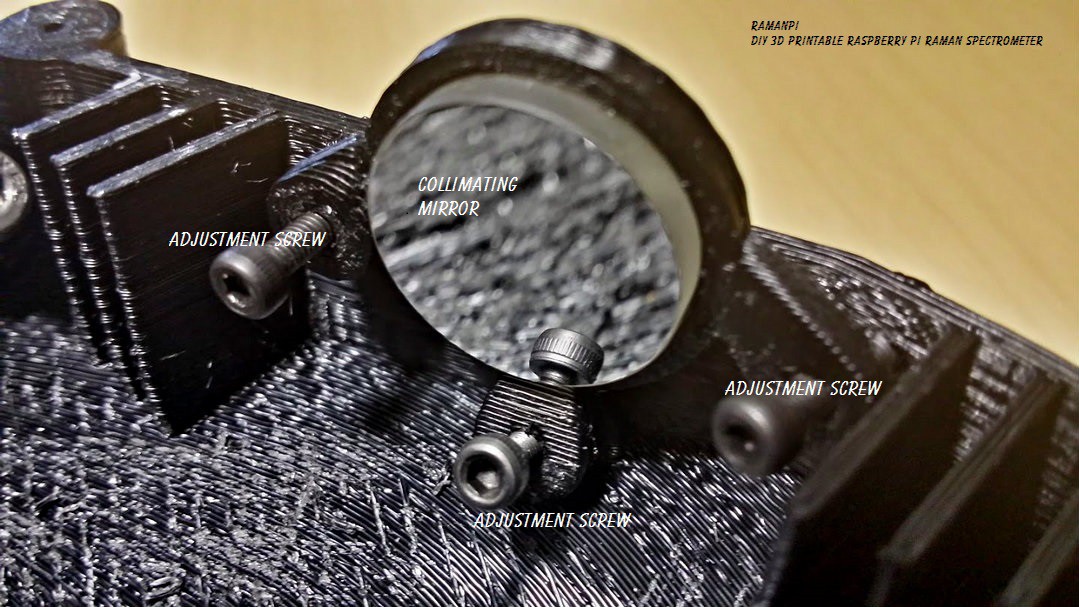
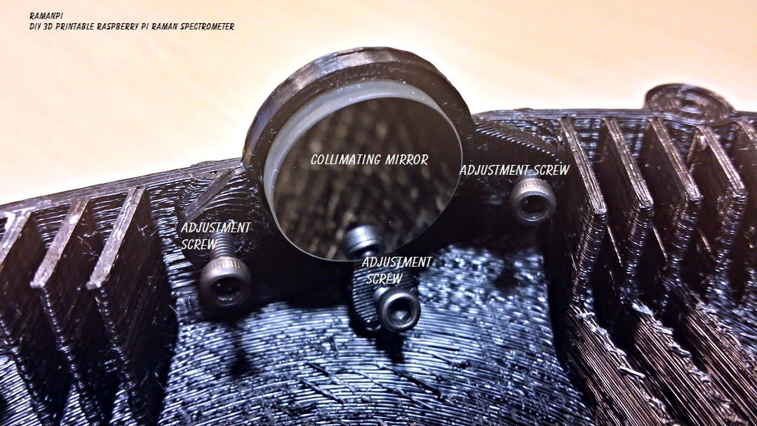
Once that is in place, turn the laser on and see where the light is ending up...It really should be hitting square in the center of the collimating mirror...If not, you have some issues..Start by making sure your laser is in the stand properly..and making sure the stand is mounted on the side of the spectrometer correctly..
With the laser on, you should see something similar to this on the collimating mirror...
![]()
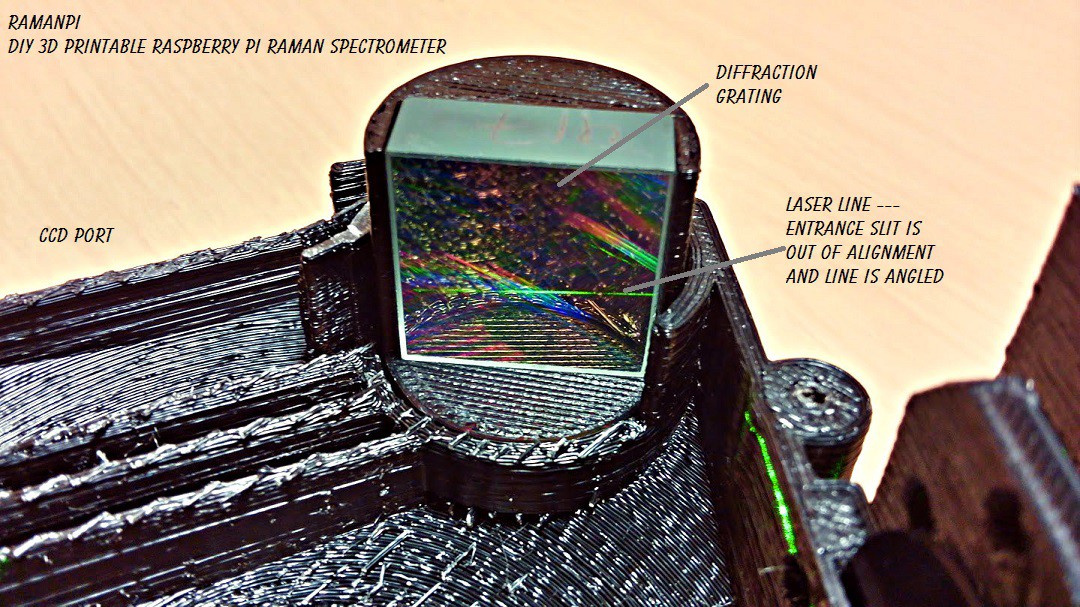
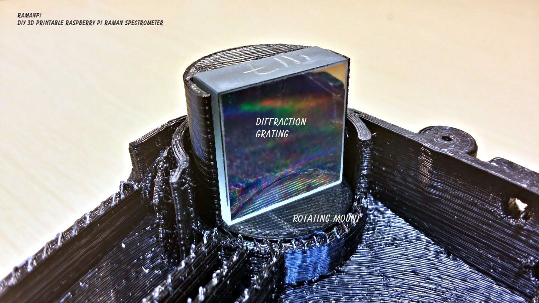
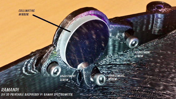
Next, with the laser on, take a look at the diffraction grating...You should be seeing a horizontal line across it...probably not centered... You'll have to adjust the three screws on the collimating mirror mount to align this.. The left screw clockwise pulls the line to the right on the grating... the right screw clockwise pulls the line to the left.. The bottom screw clockwise pulls the line downward on the grating... Both left and right screws clockwise will pull the line up... A combination of the three will allow for centering.. It takes a gentle touch and some patience..
When you are done, you should see something like this.... (Notice in this image, the entrance slit is slightly angled causing the line across the diffraction grating to be angled.)
![]()
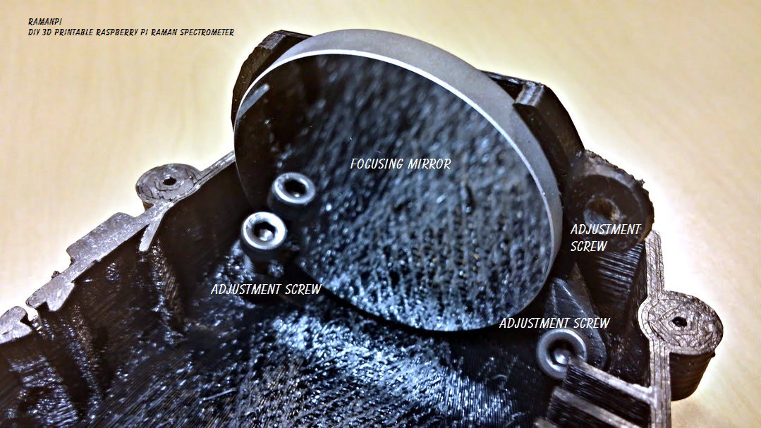
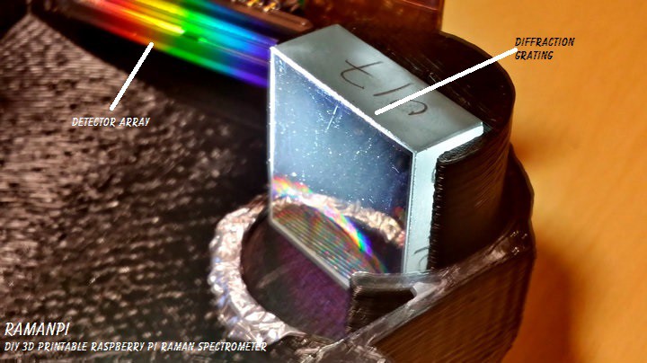
After that, you'll want to make sure the grating is reflecting the correct order onto the focusing mirror.. This will take even more patience.. And keep in mind, this is something trained professional normally do with commercial products..they usually cement the optics in place after someone has aligned them so you can't make a mistake.. To align the grating, it really only goes left or right in the rotating mount.. So, depending on your optics and grating...if it varies from my initial configuration, you'll need to do some math.. Or hopefully I'll have completed the .scad to correctly give the proper angle for the grating.. At the time of this update, it's not working 100%.. But this works until then.. Hit the power on your laser, and put the palm of your hand where the CCD goes...or if you already have your CCD mounted, look where the beam is hitting... You should also be able to see where the beam is hitting the focusing mirror... You should see the reflection of the beam off to the side of the mirror..You do not want the actual reflection pointed at the mirror...If you hold the palm of your hand to the left behind the focusing mirror you should see the beam.. Basically you want the beam to hit the focusing mirror about half way.. This image should be of some use.... Notice where the grating normal is pointed.. Then take note where the focusing mirror normal is pointed.. Orient the grating so the 1st order is just to the right from the front of the mirror) of center.. You should see the beam somewhere on your CCD board...(or palm of your hand held near the CCD port.
It should look like this.....
![]()
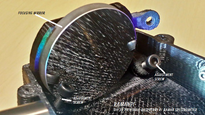
Next, the focusing mirror needs to be aligned.. Use the adjustment screws in the same fashion as the collimating mirror to direct the beam to the center of the CCD... Should be pretty straight forward...
It should look like this....
![]()
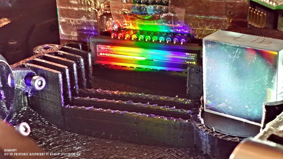
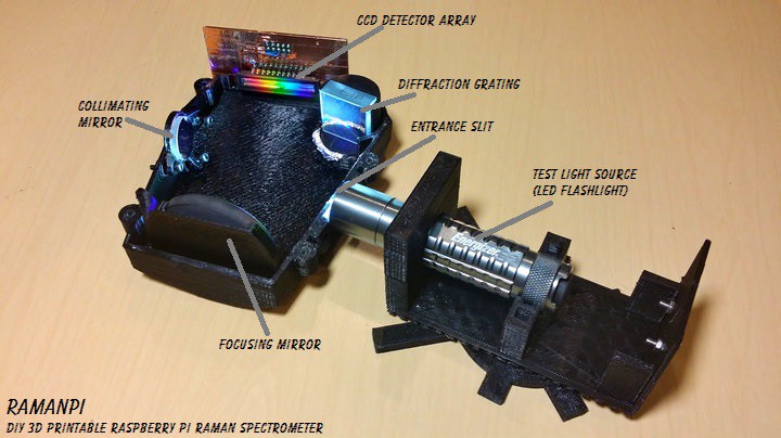
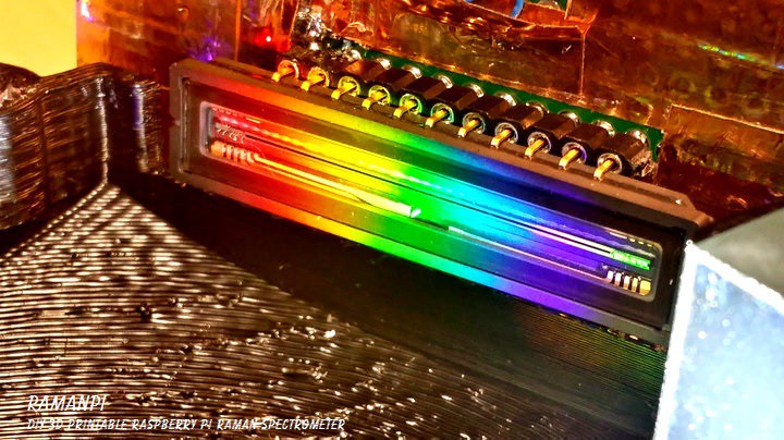
If you've followed these steps (and all the previous steps leading to this) properly.. You should be ready for some fun... Just as a quick test... Try replacing the laser pointer with a pocket flashlight... The spectra should start with red at the left of the CCD and Violet to the right... And be centered on the CCD...
It should look like this.....
![]()
From here, you will need a known light source to calibrate any further... That will be covered in the next log entry on Spectrometer Calibration...
Until then, enjoy!
![]()
UPDATE LOG:
09.17.2014 - New Entry for Spectrometer Alignment
09.18.2014 - Corrected date format
09.22.2014 - Added Spectrometer Alignment Graphic
09.23.2014 - New Logo
-
imagingBoard - schematic and board information
09/16/2014 at 04:50 • 2 comments![]()
![]()
Note: This log entry is a living document. I'll be updating this post to reflect the current configuration as time goes on.. There will also be a log at the end of the post noting modifications to the log, etc..
UPDATED-----> 10.23.2014
![]()
This log entry is where I will keep current information regarding the schematic, board layout and other details about the imagingBoard electronics and firmware.. I will reference this log entry in the 'details' section of the project page.. This log entry will probably change from time to time to reflect the current status of the imagingBoard. If you're interested, it might be worth a bookmark..
The function of the imagingBoard is as follows:
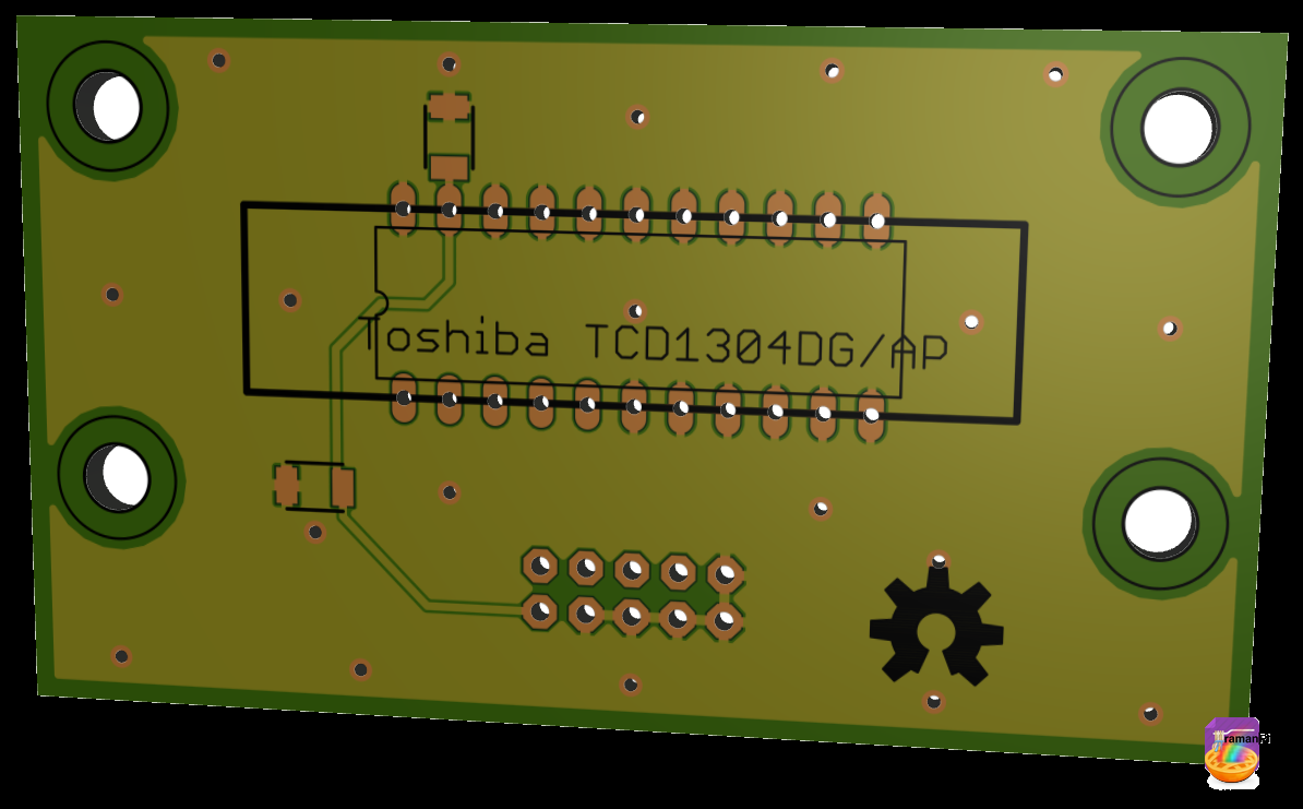
- Controls Toshiba TCD1304DG Linear CCD for imaging the spectra
- Monitors Linear CCD Detector Array Temperature via DS18b20 temperature sensor
- Monitors UV index with a SI1145 UV Index Sensor
- *Might, in future update control the Linear CCD sliding, which can be used to increase resolution.
- Transmits CCD data to raspberryPi for processing
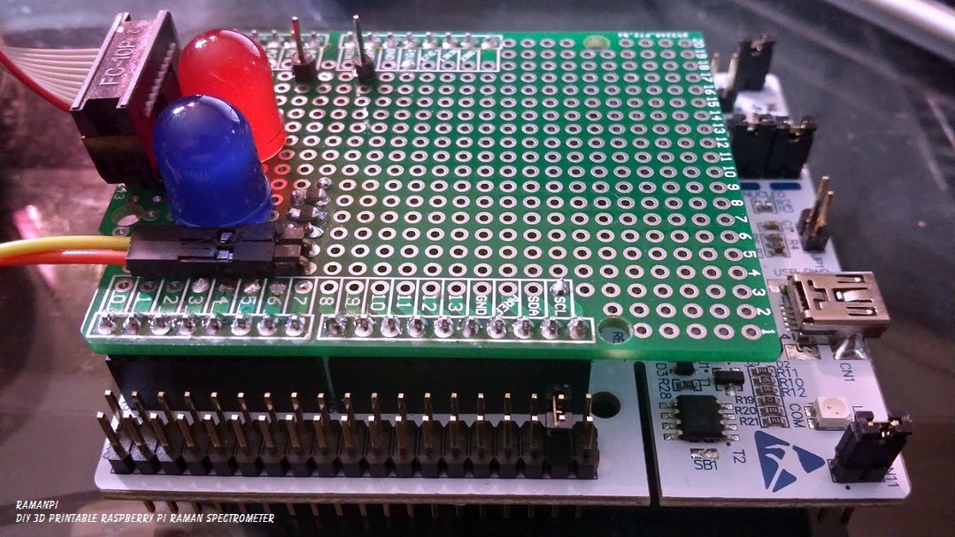
Here is what the current imagingBoard looks like...
![]()
It is basically a ST Micro Nucleo F401RE board with a blank arduino 'shield' on it's back... The daughter board has two indicator LEDs and a port that goes out to the CCD board....
Which looks like this...
![]()
Later on, these two may be integrated into one board.. There may be an external ADC, etc... but this is what it is for now...
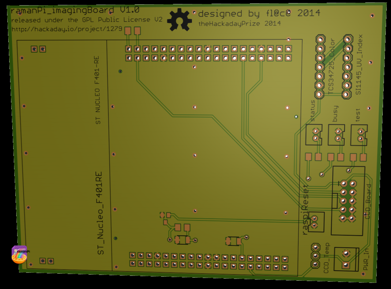
Here is the rendering of the imagingBoard main board
Top
![]()
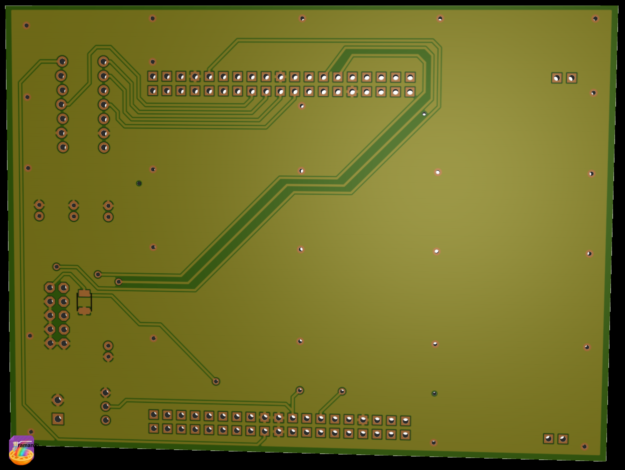
Bottom
![]()
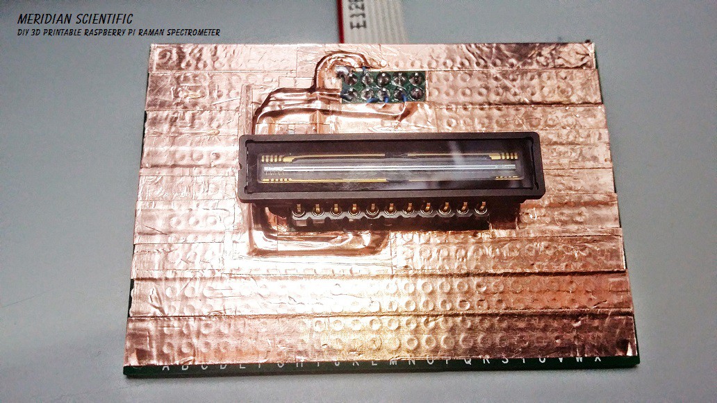
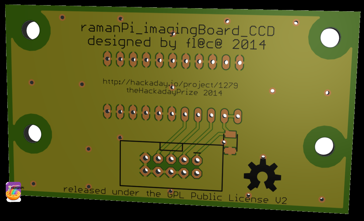
This is the rendering for the imagingBoard CCD board
Top
![]()
Bottom
![]()
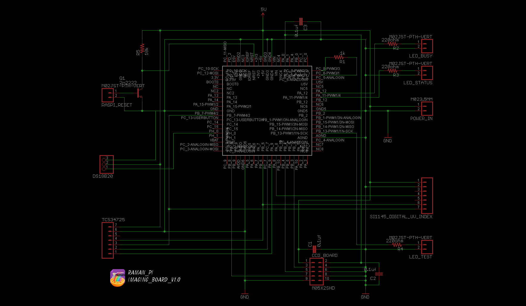
Here is the schematic for the imagingBoard main board
![]()
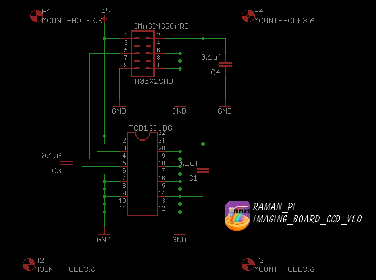
Here is the schematic for the imagingBoard CCD board
![]()
The eagle files, and the firmware are located in the gitHub
- Hardware: gitHub repository ---- alpha version here
- Firmware: gitHub repository
The board consists of the Nucelo F401RE, a Toshiba TCD1304DG Linear CCD Array, and a SI11145 Digital UV Index / IR / Visible Light Sensor (Adafruit Part#1777)..
Keep an eye out, since there will be updates here...!
![]()
UPDATE LOG:
09.17.2014 - Added living document info
09.18.2014 - Corrected date format
09.22.2014 - Added imagingBoard Graphic
09.23.2014 - New Logo
10.15.2014 - Added new schematics and board layouts for imagingBoard main board and imagingBoard CCD board
10.23.2014 - Added link to alpha version of firmware that increases sensitivity and allows better integration control
-
How to build a spectrometer
09/11/2014 at 02:45 • 41 comments![]()
![]()
Note: This log entry is a living document. I'll be updating this post to reflect the current configuration as time goes on.. There will also be a log at the end of the post noting modifications to the log, etc..
UPDATED-----> 09.23.2014
![]()
Ok.. It's been a lot of tweaking, and refining... A lot of going over the design, fixing issues and overcoming problems.. But I have reached a pretty good point with the spectrometer design.. I managed to design this part of the system so it can be used completely independently from the rest of the raman setup.. You can print this portion, install the optics, setup the fairly simple electronics, configure the software, make some minor adjustments to the optics so they're properly aligned, hook it up to a PC (or the ramanPi) and get some work done!
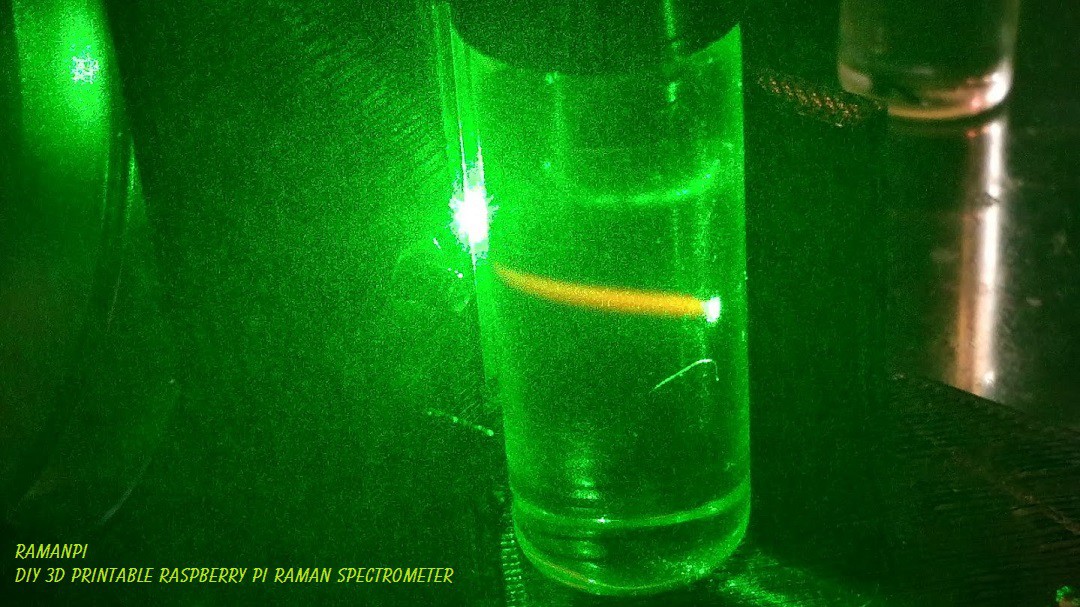
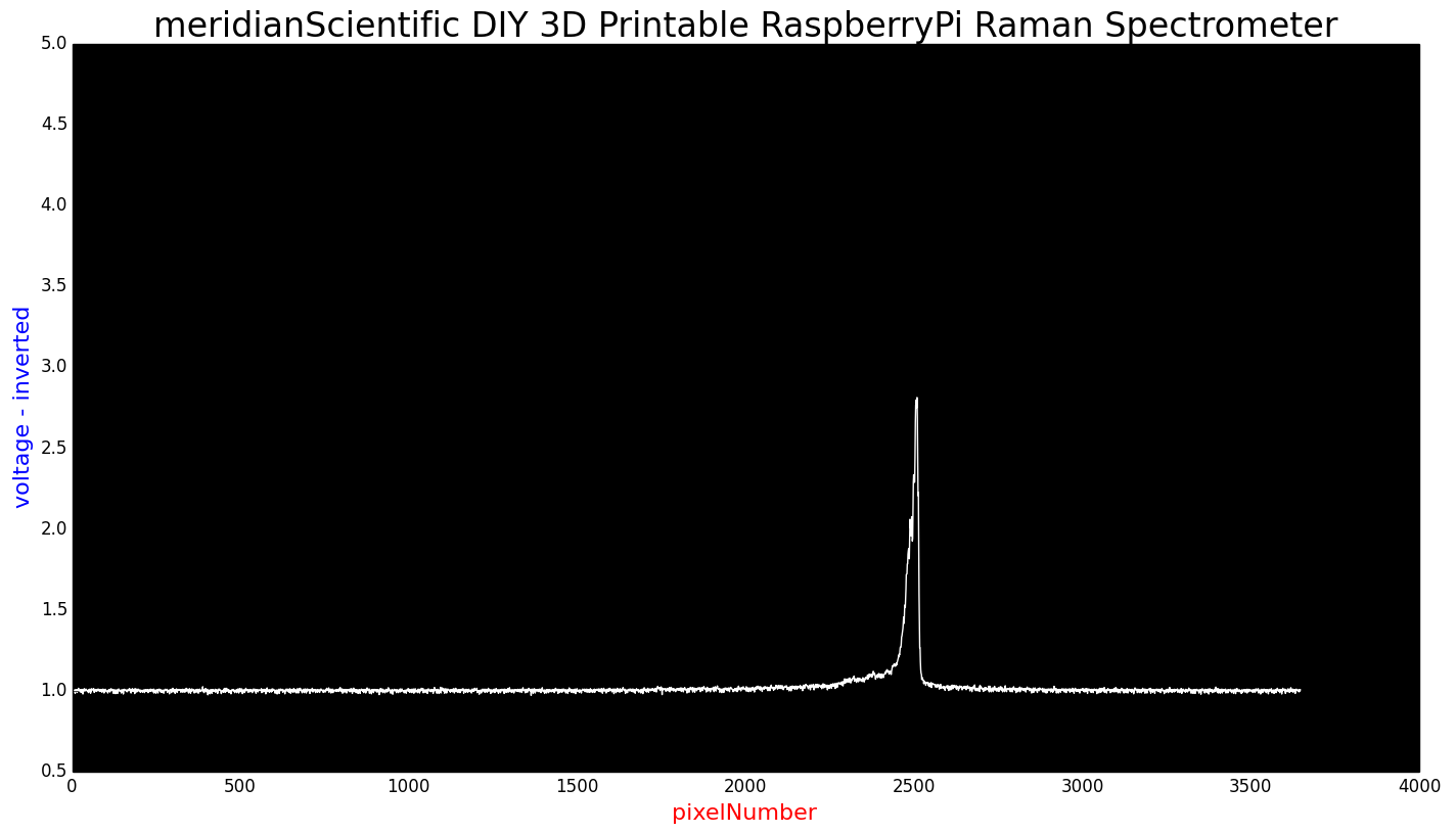
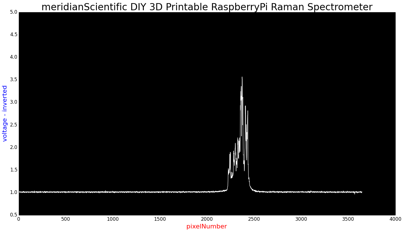
This spectrometer should be about on par with what you'd get from an ocean optics commercial product... Well, at least as good as one could expect to get.. I might experiment a bit with better options than razor blades for the entrance slit.. But really, the diffraction grating is pretty much on par, the CCD is the same model... we should be getting some great results... I need to calibrate mine with a known light source... I have a neon ampoule, and a mercury vapor lamp...I'll be trying those out pretty soon.. In the mean time, I did a quick sample with a 532nm laser.... Here's the result from that...
![]()
I'd call that pretty clean considering it is my first try... and it's a cheap eBay handheld laser pointer... Unfortunately, we can't use that to calibrate the spectrometer...
HOW TO BUILD A SPECTROMETER - PART 1
I wanted to make this post a sort of how to for assembling the spectrometer... as much as I can anyway... So, here's a quick guide...!
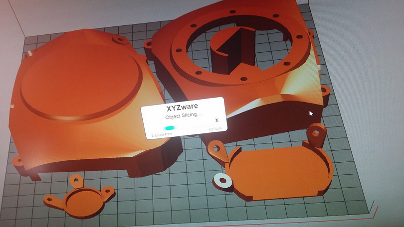
We start by loading up the files to print the plastic parts...
![]()
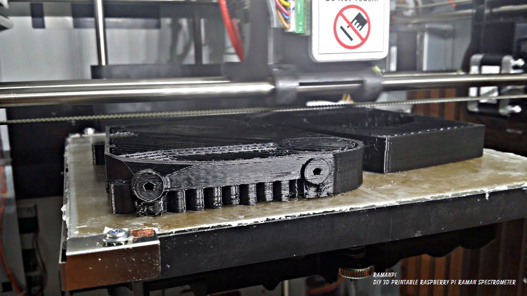
Set up the printer and start printing.... Wait a good 12-18 hours....
![]()
Keep an eye on it every once in a while...
![]()
And then you have the makings of quite a few lost weekends to come..
![]()
Once you've removed it from the printer... There's going to be a little cleanup required... All the supports, and rough edges, screwholes and everything need to be free of debris, etc..
![]()
![]()
![]()
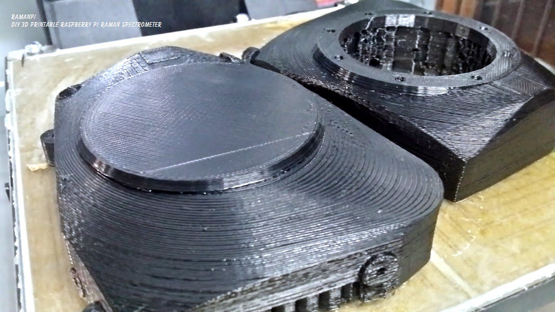
Once you get that all cleaned up.. Your spectrometer parts should look something like this...
![]()
![]()
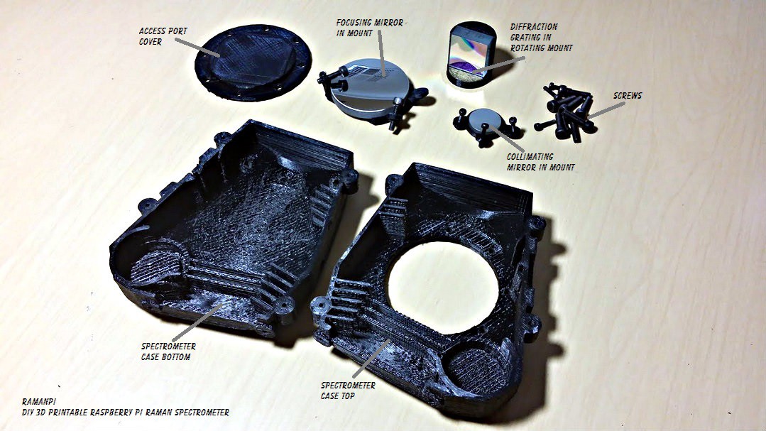
Gather your other parts... The access port cover, the necessary screws, the diffraction grating..the collimating mirror, the focusing mirror...the mounts for the optics...your imaging board and the CCD board...
Here are the parts I designed this version of the spectrometer to use..and is what I am using in mine..
The diffraction grating... Stock No. #43-216
- Edmund Optics 1200 Grooves/mm, 25mm Square, VIS Holographic Grating ...... $135.00
The collimating mirror.... Stock No. #46-239
- Edmund Optics 20mm Dia x 80mm Focal Length, Spherical Mirror ....................... $37.50
The focusing mirror... Stock No. #43-471
- Edmund Optics 50mm Dia. x 100mm FL Protected Aluminum, Concave Mirror ... $42.50
![]()
I'll post the specifics on mounting the optics in their mounts soon, but for the moment, lets assume they're already mounted..
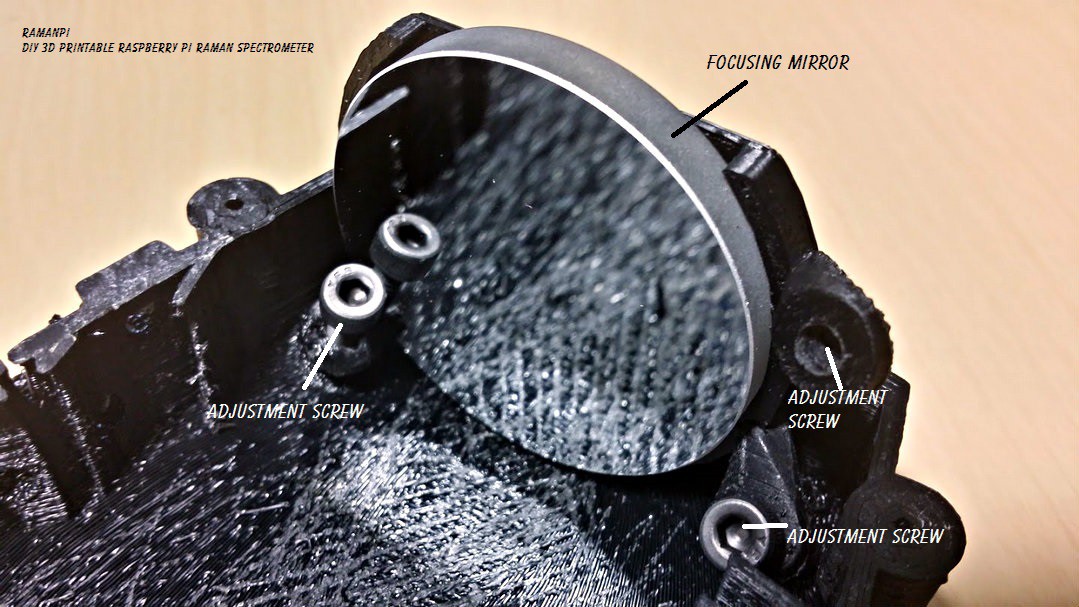
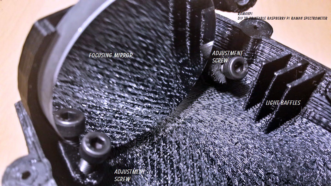
Go ahead an place the focusing mirror assembly in place and screw in the adjusting screws...
![]()
![]()
And always... make sure you're wearing proper gloves, and not to touch the surface of the optics!!!
![]()
Now, let's go ahead and place the collimating mirror assembly into place and screw it in...
![]()
Again, make sure to be very careful not to touch the surface!
![]()
Once that's in place, go ahead and place the diffraction grating assembly in...
![]()
BE EXTRA SUPER VERY MAJORLY CRAZY ULTRA CAREFUL NOT TO TOUCH THE DIFFRACTION GRATING SURFACE!!!!!!!!!!!!!!! ANY CONTACT WILL RUIN IT... Just look at mine... :( It fell on it's face on a very clean surface and is going to have to be replaced...
![]()
Here is what you should have at this point... A very nice start!
![]()
At this point, your optics are probably going to be way out of alignment.. We'll have to make sure they're all snug and aligned before we can use this thing for anything...
![]()
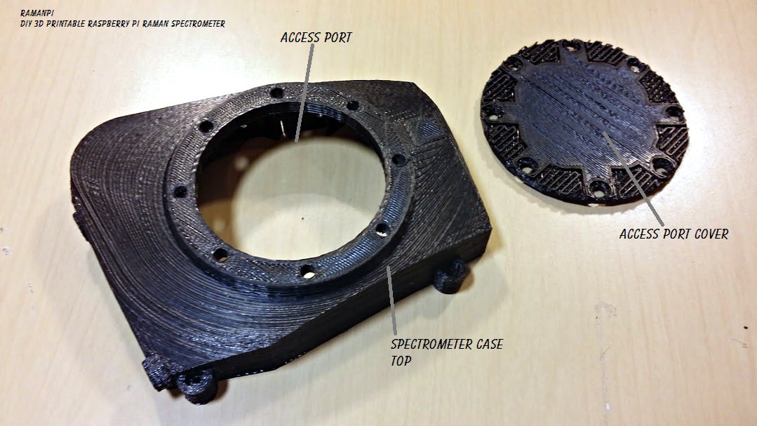
But we'll cover alignment in another project log as well... For now, let's follow through with getting this thing assembled! Take your top and the access port cover...get the mounting screws........
![]()
Place the access cover over the access port and align the holes....
![]()
Place the screws in place and start tightening them! I recommend an alternating pattern...
![]()
And there we have a spectrometer!! Almost ready for use!
![]()
We will cover placing the CCD board in another post as well... But this is where it goes.. :)
![]()
Looks great doesn't it???
![]()
Here's some sneak preview pictures of the alignment process...
If you can't tell, I'm pretty happy with how this part came out.....
![]()
![]()
![]()
![]()
I'll be picking up where I left off with the electronics and software now... And I am aiming for raman spectra by the end of the month!! This is a quick little test I did (not calibrated) using some filters... More on this soon!!!
![]()
Does this look good on me?
![]()
LOL...
![]()
Edit:
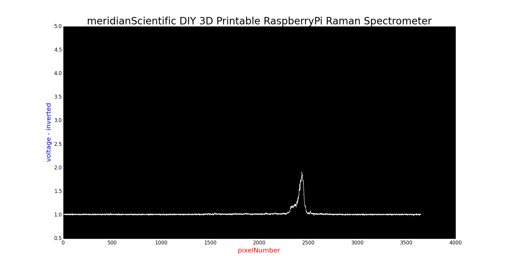
A little better example of the 532nm laser... I think I had the beam misaligned on the first image... This one's not as strong, but I closed the entrance slit a tiny bit...
![]()
Update: 09.18.2014
Here is a much better signal from a better aligned laser in the test stand bolted to the side...
![]()
![]()
Update Log:
09.17.2014 - Started maintaining this post as a living document.. Added Title to start of instructions.
09.18.2014 - Added 532nm laser spectrum update at bottom...
09.23.2014 - New Logo
-
Even more spectrometer!
09/09/2014 at 07:17 • 0 comments![]()
I'm sure people are tired of seeing the spectrometer... I know I'm just about there... But, progress is progress...and this is a pretty important part...and it's pretty complex..... So.... Check this out...
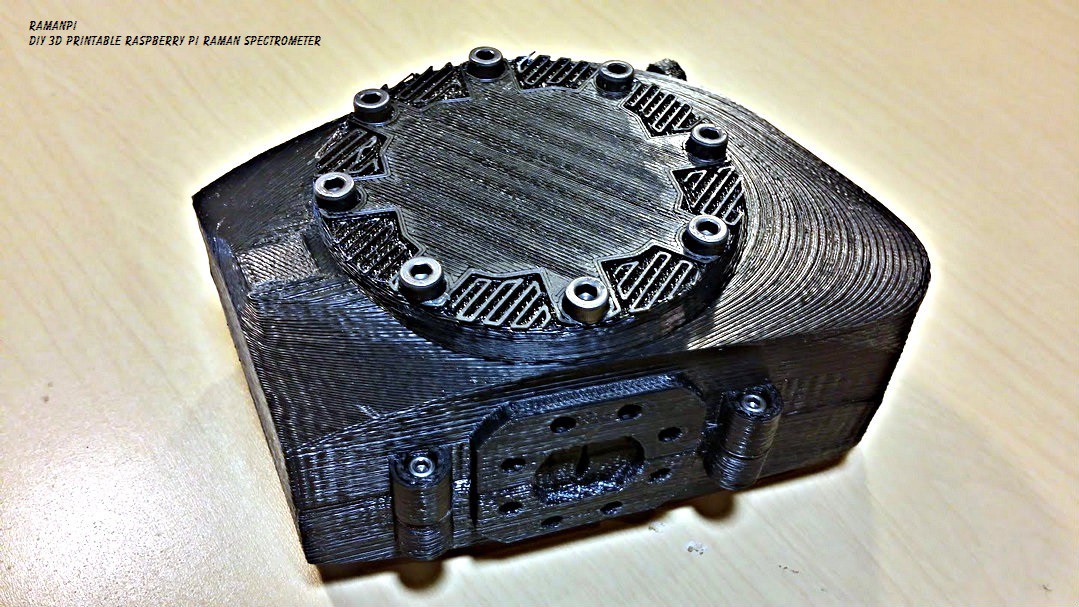
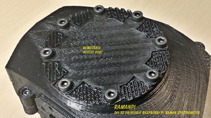
The next to final version... (This one doesn't have the baffles inside, but has everything else) Notice the access port cover... Ooo0oo0h..
![]()
Here's a slightly closer shot of the cover in place...
![]()
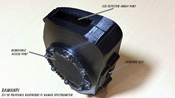
And the whole thing on end...with no CCD mounted...
![]()
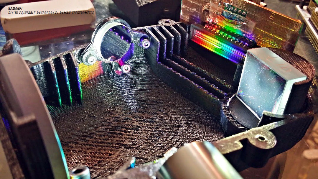
And here we see it cracked open with the optics in place and working... No baffles here yet..that's in the next print...(probably starting the print tomorrow)..
![]()
A nice overview..
![]()
Another angle... My optics are a little dusty... =/
![]()
A little closer shot... and you can see my poor diffraction grating got a little scratched... I'll probably be replacing that when I finish this thing up..and it'll probably be the last thing I put in there before closing it up.
![]()
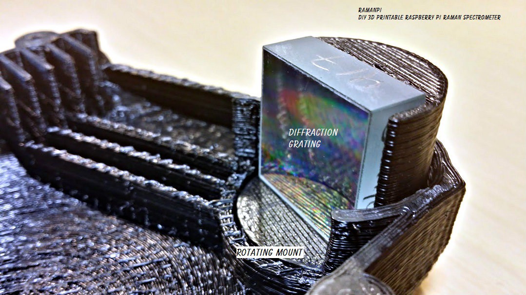
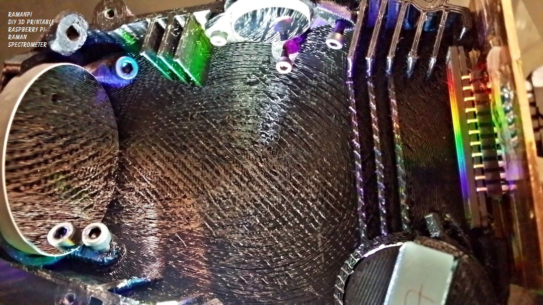
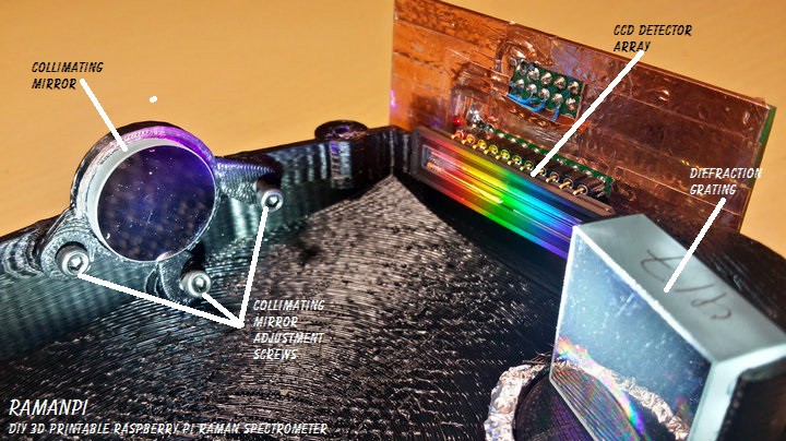
Here you can see the mount for the collimating mirror, which has three adjustment points..allowing you to pinpoint the light on the diffraction grating...this setup proved to work VERY well... Dusty mirror =(
![]()
Here's my sad diffraction grating in it's rotating mount...which might end up with a small stepper motor in the final version... But this works very well..
![]()
And here we have the focusing mirror mounted in it's nice little adjustable bracket too... The adjustment screws work great...
![]()
A nice little overview...
![]()
Got to love that color.....
![]()
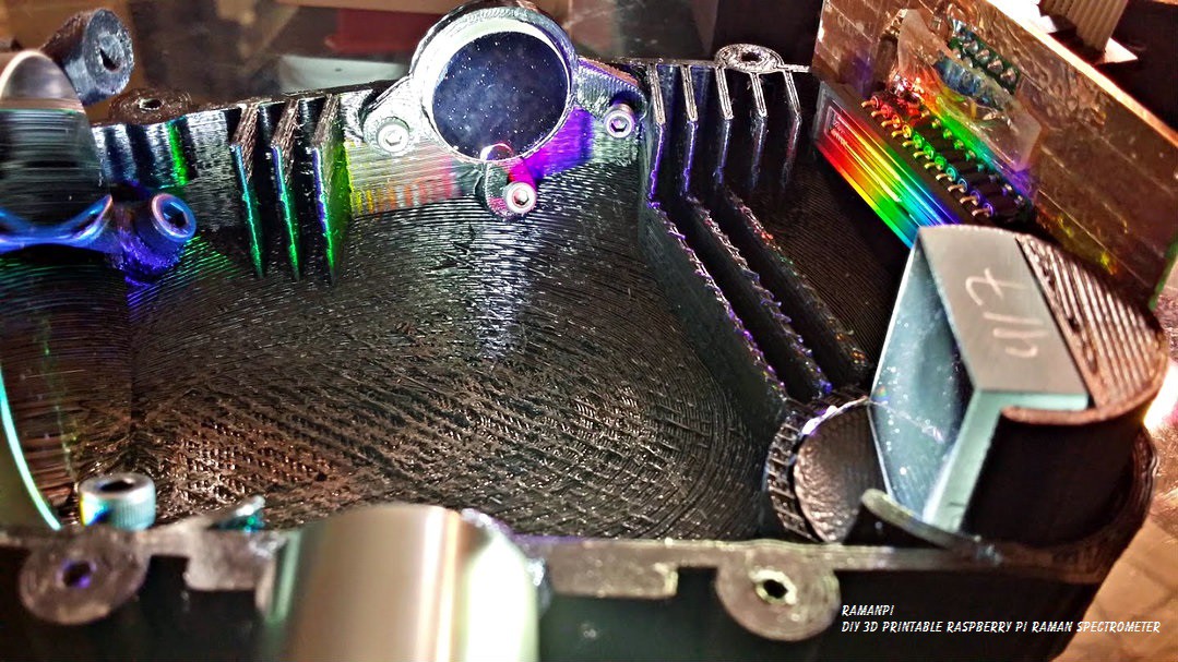
A nice angle showing the collimating mirror, detector array and the diffraction grating... Take note of what this looks like...after a couple days, this will look much different with the light baffles in place....
![]()
One last internal shot... I am very happy with how this is coming out...
![]()
And an external shot with the led flashlight in place.. :)
![]()
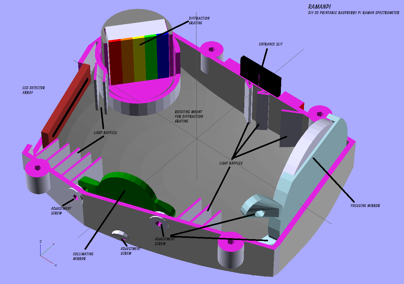
Here's a couple renderings of what it'll look like with the light baffles in place!!
![]()
The other side...
![]()
As always.... I'm happy to hear what you think!!
![]()
-
ramanPi - Now with more spectrometer!
09/06/2014 at 22:37 • 2 comments![]()
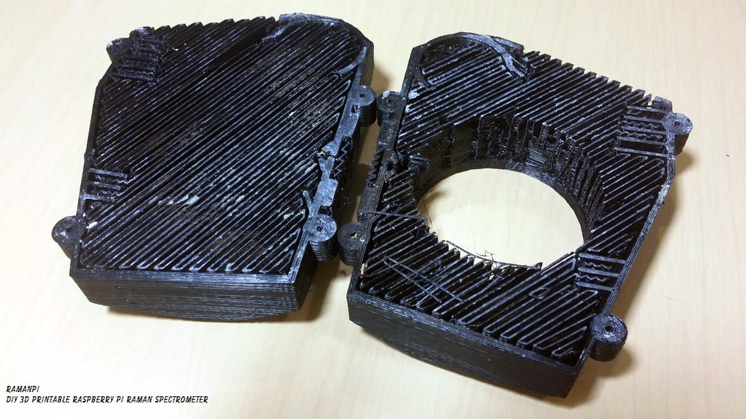
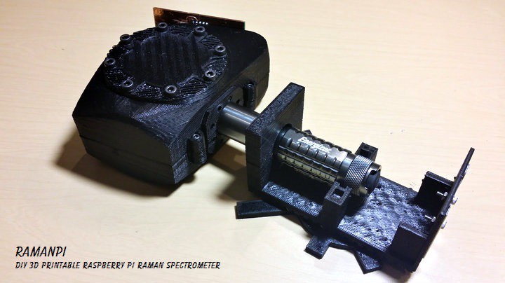
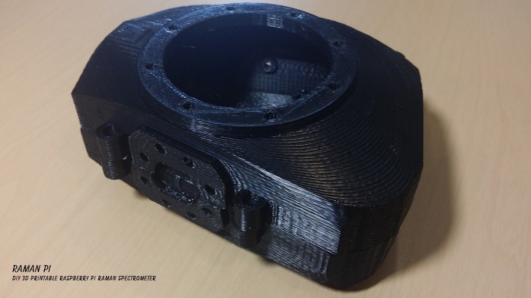
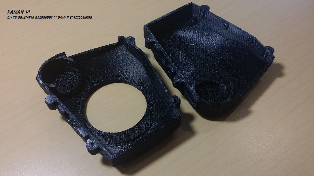
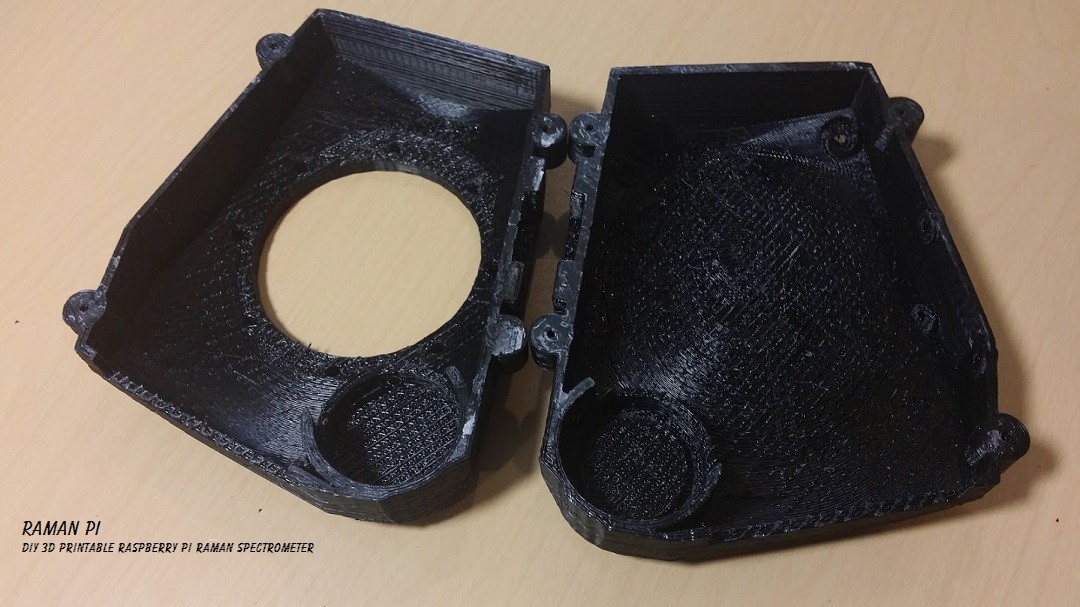
After a good cleaning, and re-calibration of the printer...and about 16 hours of printing... I have success.. Here is the spectrometer top and bottom!
![]()
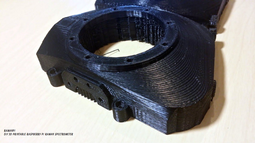
With the entrance slit facing us...
![]()
Top on the left and bottom on the right...
![]()
I'm very happy with the way this came out... Now it's time to put the whole thing together!!!
![]()
I'll post some in progress shots of assembling it, with the optics, etc... soon! I didn't include the light baffles, etc... because I want to work out the best configuration... This is still a rough version, albeit much nicer than the last...but the screwholes need to be widened up a bit too...mostly for the four mount points and the collimating mirror mount.. Updates soon to follow!
![]()
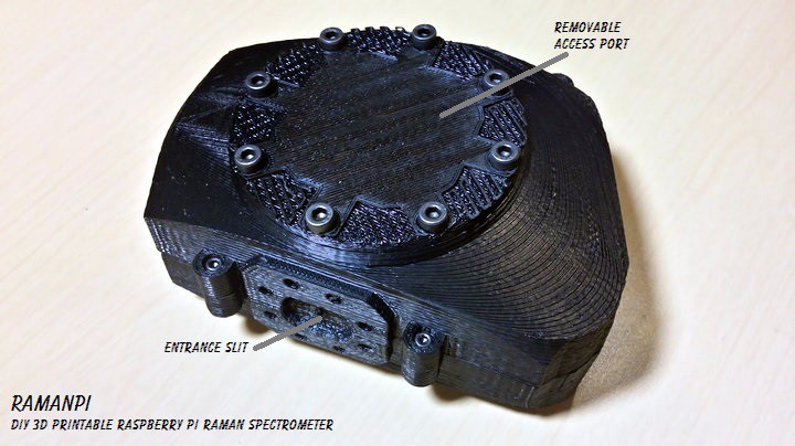
ramanPi - Raman Spectrometer
The open source 3D Printable Raman Spectrometer using a RaspberryPi and easy to find off the shelf components..