fl@C@
fl@C@-
More 3D Printer Problems
09/05/2014 at 17:59 • 2 comments![]()
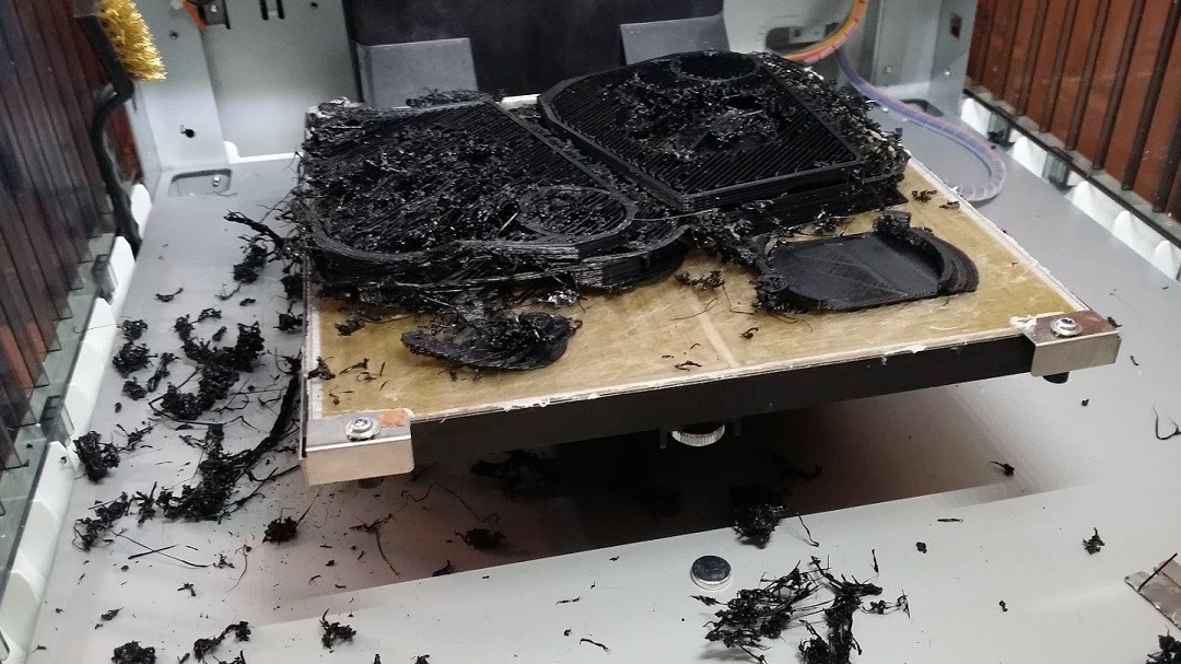
Well, I set up the spectrometer for another trial print...this time with all of the mounting points, and mounts for the optics in place.. I've been using the glue sticks that come with the davinci printer..they work amazingly well.. This time, I had just ran out and tried another brand... Nope. Nothing sticks... didn't get very far... So I got some of the same brand I have been using... And went with that... the spectrometer at the quality print I selected was estimated for a 12 hour print..
I set up the print, got the print bed all setup....and then watched it for the first 5-10 minutes... looked great... So, I went to watch a movie... came back and.... AGH.. distaster..
![]()
That doesn't look like a spectrometer at all...!
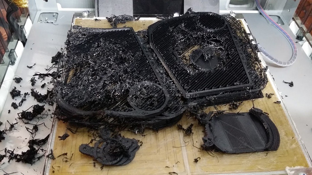
![]()
So, looks like another cleaning is in order.. That didn't last long.. and this was a new filament cartridge too.. Hopefully I can get it going again very soon.. Has anyone else experienced these kinds of failures with their printers so often? I know I'm printing a lot, but I can't imagine it's that much more than a lot of people do...
![]()
-
Spectrometer Progress
09/02/2014 at 05:30 • 0 comments![]()
Here is a quick report of my progress with the spectrometer design.. It's nearly complete. I have some minor details to finish up, like baffling, the access port, the focusing mirror mount.. and the CCD mount.. I printed a test and it looks pretty good. I had to make a couple minor adjustments to ensure it will fit into the case...but I think it should be good now.. I've finished up my tests with the test stands, they were pretty helpful.
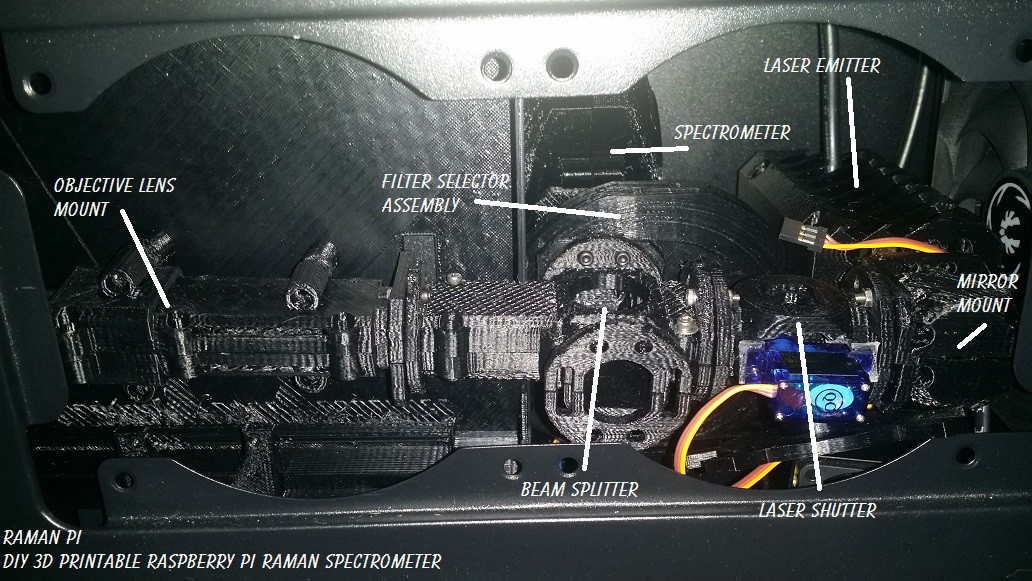
Here's the shots of the system fitted into the case and just about ready to mount up with all the optics!
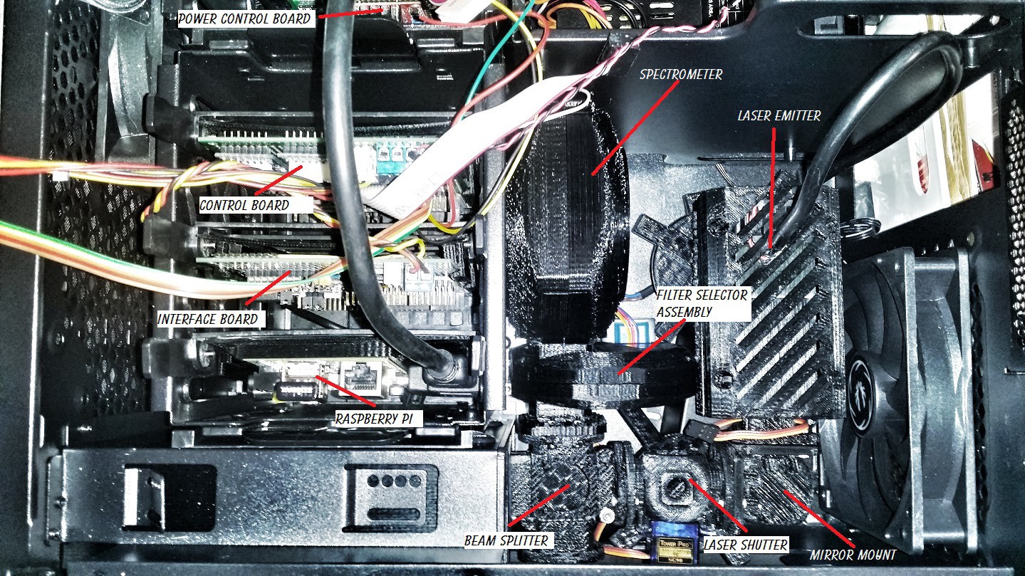
This is a shot from the side with the side of the case open.. The spectrometer is way in back behind the filter selector...
![]()
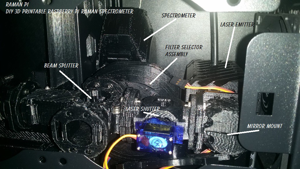
Here you can see it a little better...
![]()
A view from above...with the top of the case open.. You can see the electronics bay to the left(front of the case).. The spectrometer is just about center of the picture...
![]()
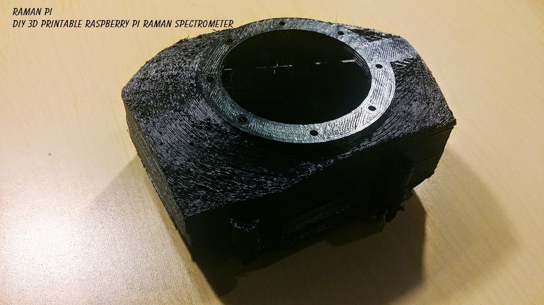
Here's the prototype that I printed up... a little rough since I used the low res settings just for this test...But it looks great!
![]()
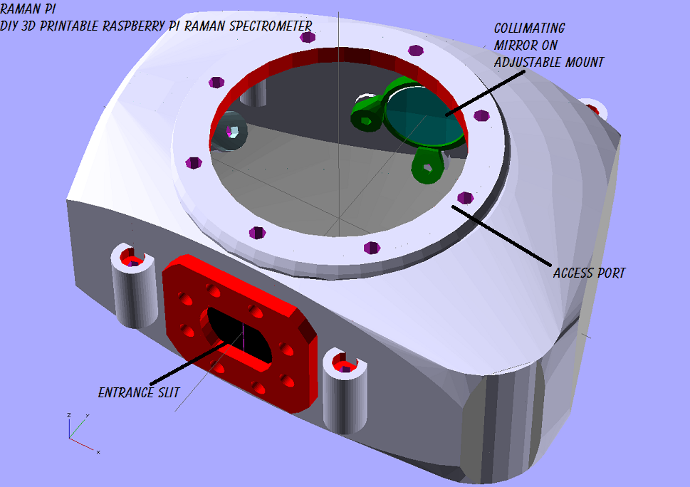
Here's what it'll look like very soon...
![]()
Another view...
![]()
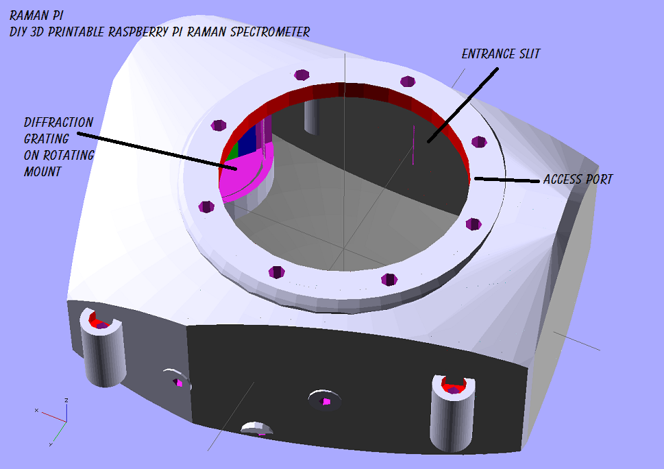
A cutaway...with the top off...
![]()
And the other side....
![]()
The mirror mounts will be screwed to the casing with a rubber grommet to keep them snug and provide a little shock proofing.. The diffraction grating may end up on a stepper motor eventually.. The CCD may also end up on a motorized mount..
I should have it finished up and ready to print tomorrow..!
![]()
-
Small step in the right direction..
08/29/2014 at 17:35 • 0 comments![]()
Been spending a little time hammering out the spherical mirror reflection angles.. Made a little .scad file that pretty well simulates the ray paths for a given incident angle and shows where to reflected rays are.. This is of course, going into the spectrometer designer so people can use whatever mirrors they can grab and plug that into openSCAD and it'll spit out a spectrometer ready to print based on your optics...
Here's a little gif showing the incident angle changing...and the reflected rays acting accordingly..
![]()
Here's the code to generate this example.. It has a couple limitations, but I don't anticipate two axis angles, and to compensate for the mirror rotation, you can just change the angle of incidence..
/*
Limitations to this....
	Only two dimensional for now..
	Doesn't compensate for changing mirror angle..mostly..yet...
*/

//animate
function saw(t) = 1 - 2*abs(t-0.5);

pi = 3.14159265359;
FM_D = 50;		// focusingMirror Diameter
FM_EFL = 100;		// focusingMirror Effective Focal Length
FM_R = 200;		// focusingMirror Radius
FM_ET = 6;		// focusingMirror Edge Thickness
FM_Xr = 90;		// focusingMirror X rotation - up and down
FM_Yr = 0;		// focusingMirror Y rotation - rotates around normal
FM_Zr = 90;		// focusingMirror Z rotation - left to right
FM_Xp = 0;		// focusingMirror X position
FM_Yp = 0;		// focusingMirror Y position
FM_Zp = 0;		// focusingMirror Z position

incidentAngle = 60;	// angle of incoming light
numberOfRays = 45;	// number of rays to draw
rayStep = 5;		// distance between rays

module mirror(){
	difference(){
		translate([FM_Xp,FM_Yp,FM_Zp]) cylinder(d=FM_D,h=FM_ET,$fn=100,center=true);
		translate([FM_Xp,FM_Yp,(FM_Zp+FM_EFL)-0.5]) rotate([0,90,0]) color("lightblue") sphere(d=FM_R,$fn=100,center=true);
	}
	translate([FM_Xp,FM_Yp,FM_Zp]) color("white") cylinder(r=.25,h=100);
	translate([FM_Xp,FM_Yp,FM_Zp+100]) color("white") sphere(r=1,$fn=100);
}

module ray(incident,height,cR,cG,rB){
	focalLength = FM_EFL;
	normal = atan(height/focalLength)+FM_Xr;
	reflected = normal - incident + FM_Xr;
	a = sqrt((height*height)+(FM_EFL*FM_EFL));
	b = (100 - a) + 3;
	//incidentRay
	translate([-b,0,height]) color([1,cG,cB]) rotate([0,incident,0]) cylinder(r=.2,h=focalLength*2);
	//mirrorNormal
	translate([-b,0,height]) color([cR,1,1]) rotate([0,normal,0]) cylinder(r=.05,h=focalLength*1.5);
	//reflectedRay
	translate([-b,0,height]) color([cR,1,cB]) rotate([0,reflected,0]) cylinder(r=.2,h=focalLength*2);
}

for (i=[-numberOfRays/2: rayStep :numberOfRays/2]){
	translate([-.5,0,0]) ray(saw($t)*70+20,i,0,0,0);
}

translate([-3,0,0]) rotate([FM_Xr,FM_Yr,FM_Zr]) mirror();
It works pretty well, and I should have this integrated into the near final version soon..
So, just to show I'm making progress in other areas as well... Here's what I am using right now to get some code and finalize my design for the spectrometer I'll be using.. As a result of the previous tests, this fits my optics, and has all the correct focal lengths and angles.. I am also testing baffling, etc. using this.. (The difference between this and the last setup is the base....it has a set geometry and will only allow for adjusting angles, not distances..which is proving useful over the previous setup..But, just like the previous test setup...this is a throwaway and will not be in the final design, just for tests....)
![]()
![]()
![]()
-
More Spectrometer Design Fun
08/27/2014 at 09:19 • 0 comments![]()
What have I been doing this past week? In a nutshell...taking a crash refresher course in trig and burying my head in the web reading about ray tracing and and a bunch of head scratching with openSCAD on getting objects to change angle and position based on another objects angle and position... For example, the entrance slit shines light onto the collimating mirror... that mirror reflects and collimates the light onto the diffraction grating..... I am working on getting openSCAD to automatically position the grating based on the mirrors parameters ...diameter, focal length, angle and so on.. that makes the diffraction grating move so it's in the right place to reflect the correct order (chosen with a parameter) to reflect onto the focusing mirror. I've been pretty successful so far.. I'm still working on getting it to calculate the diffraction angles..that gets kind of tricky because it almost turns into a feedback loop since the angles change for each order depending on the angle of incidence..
![]()
My main goal with this is to get this part of the system to be as flexible as possible.. So someone who wants to build one can just plug in the numbers for the optics they were able to procure and the spectrometer will pretty much design itself so they can print one on the 3D printer with all the right focal lengths and angles for their specific optics. I have maybe a couple more days work to go with it and then a round of cleaning up my ugly code...
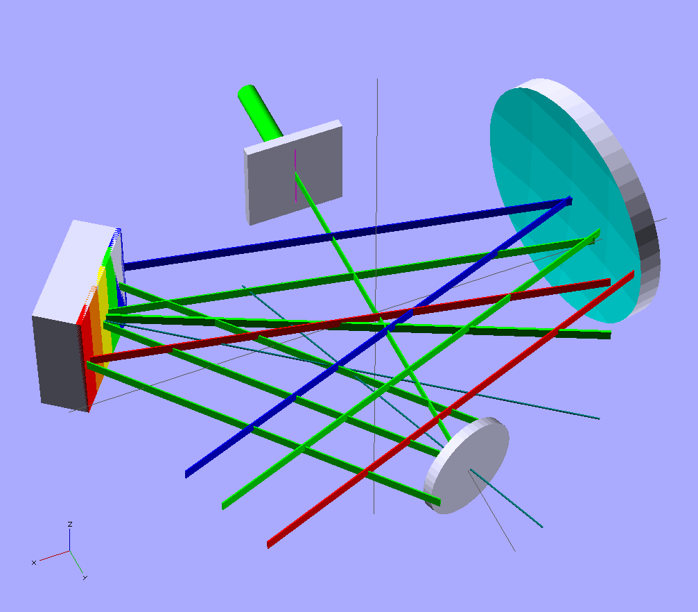
But as you can see here... it's not terribly far off the mark...although there is a lot left to fix..
This picture is ugly, but it shows the beam paths(although not correctly for the focusing mirror since they don't converge to the focal point of the spherical mirror yet) for the light as it goes around.. In this first one, you can see the collimating mirror is at a 20deg angle, the grating position and angle is automatically calculated... then the focusing mirror is automatically positioned from that...it's angle and the position of the detector array will follow suit..
![]()
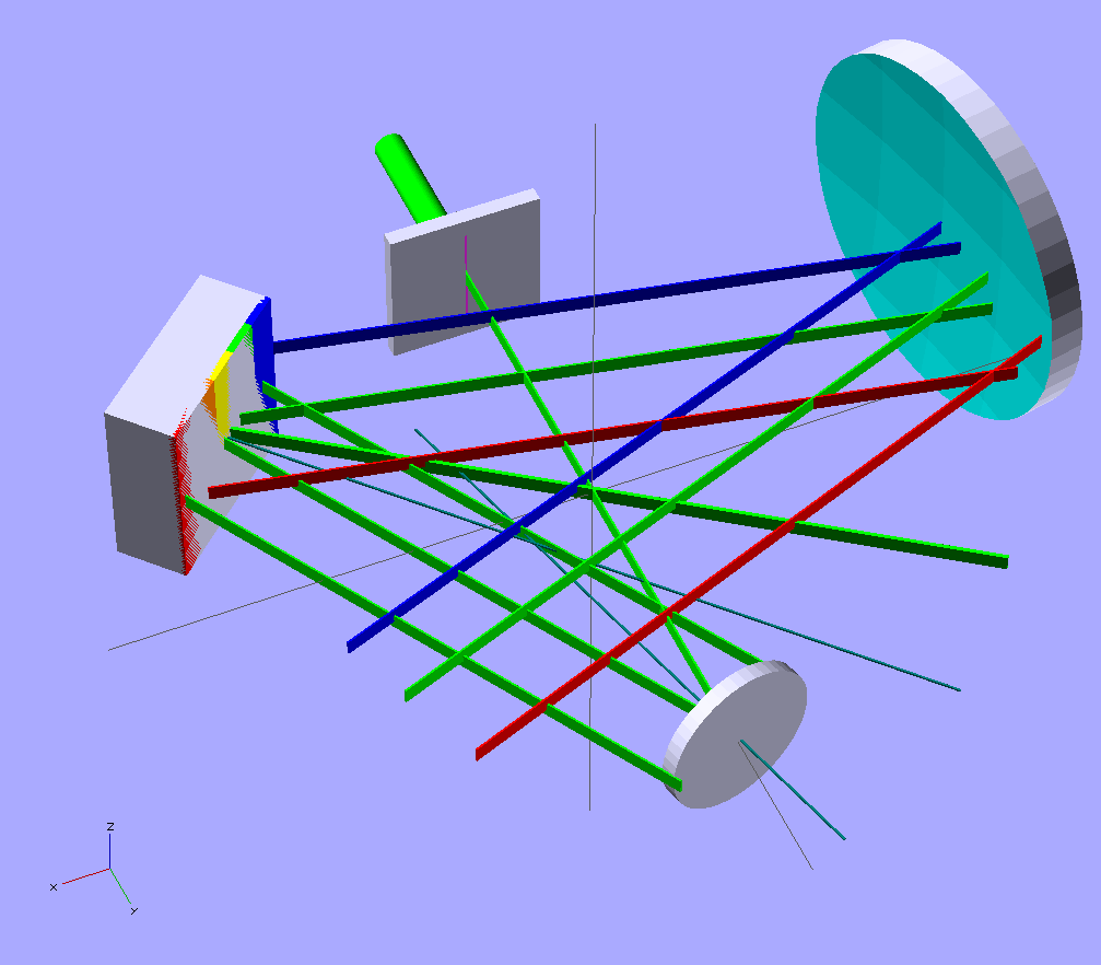
In this second image, I changed the angle for the collimating mirror to 15deg instead of 20....
![]()
Not a HUGE difference since it's only 5deg, but you can clearly see that it moved the diffraction grating and changed its angle as well as moved the focusing mirror to compensate...
The calculation (however ugly it is at the moment since this is a rough sketch so far) for calculating the diffraction grating based on the collimating mirrors parameters are as follows:
// diffractionGrating X position calculated from collimatingMirror angle and distance
DG_Xp = CM_Xp + CM_EFL * cos((CM_Zr*2) - 90);
// diffractionGratingY position calculated from collimatingMirror angle and distance
DG_Yp = CM_Yp + CM_EFL * sin((CM_Zr*2) - 90);
// diffractionGrating Z position
DG_Zp = 0;
DG_AN = DG_Zr + 90;
DG_Xp, DG_Yp and DG_Zp are the X, Y and Z positions for the diffraction grating...the CM X,Y and Z are for the collimating mirror... and the CM_Zr is rotation... DG_AN is diffraction grating angle. The same set goes for the focusing mirror pretty much to calculate its position and angle.
Here's a little animation showing the relationship of the collimating mirror and the diffraction grating.. I obviously have a lot of work to do still..
![]()
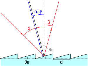
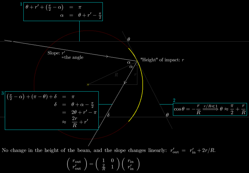
The math for the concave mirrors is pretty tough to do in openSCAD.. At least with my experience so far.. Here's an example from wikipedia.. Not so much of a worry for the collimating mirror, but is for the focusing mirror..but I might be lucky that the mirror is at its focal length.. But still more reading is required...
![]()
But..when I'm done, it will be very simple to customize the spectrometer!
For fun, try reading this.. http://en.wikipedia.org/wiki/Geometric_optics or this http://en.wikipedia.org/wiki/Blazed_grating or play with this calculator!
I'm going to go ahead and make another update to this post since I was distracted while posting it and forgot my main focus..no pun intended. I'm trying to figure out a way to not only automatically calculate the positions and angles for each mirror and the grating and detector....but I want it to visualize the rays for a preview as well.. openSCAD has posed a couple of challenges for me in this dept. I just found out earlier that apparently you cannot increment or change for that matter, variables.. So, no loops that increment a value.. That poses a problem for my first attempt at using the Bresenham Line Algorithm to test an idea for tracing the rays... Before this project (a couple months ago), I hadn't really used openSCAD for more than a few minutes.. I really like it, because it works more the way I think than pushing a mouse around, but there are some severe limitations.. If anyone has a good idea of how to trace and plot a ray using really any language, I'd love to see it..
![]()
-
Spectrometer Physical Design Concept
08/21/2014 at 10:59 • 0 comments![]()
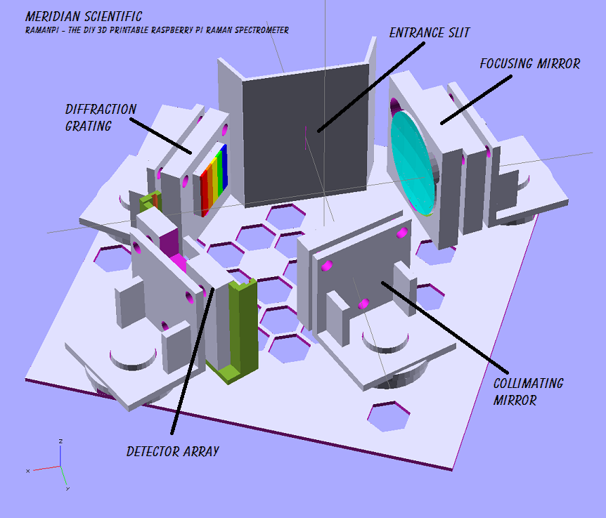
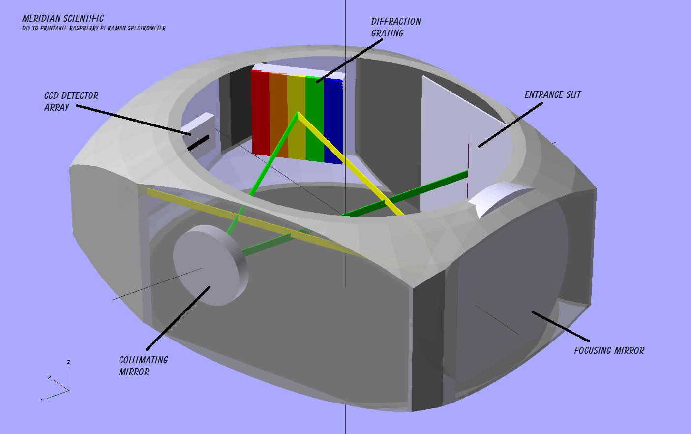
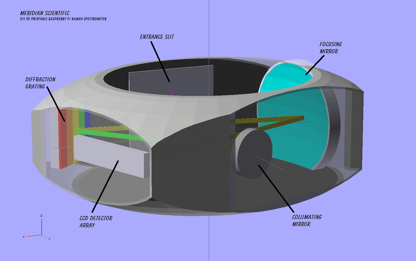
I have been playing around with different ideas for the past week on physical designs for the spectrometer... Aside from the geometry, and other design aspects.. I needed to develop a physical 3D printable case to fit the optics in, etc.. So here are a couple renderings on what I think might be the start of the final idea.. :) It's very simple right now, no details.. just basic placement and shape... But from everything I can figure, and a whole lot of attention to whether it will fit into the case with all the other parts and optics...I think this should work well.
Here are the renderings...
![]()
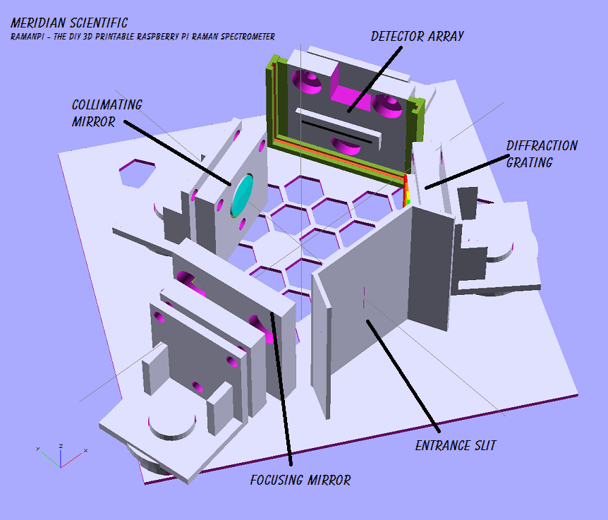
Like I said..pretty basic right now.. I think I got enough from the testing with the test stands that I made in my previous round that I am pretty happy with the geometry and focal lengths, etc.. etc.. etc..... I will be adding adjustable mounts for the optics to allow for fine tuning, etc.. and might be adding a stepper motor for both the diffraction grating and the CCD array.. I'm very interested in the idea of increasing the resolution by taking a sample, then sliding the CCD a tiny bit and taking another sample, etc.. and adding those up... Theoretically, that should provide for a pretty decent gain in resolution... and actually might be very useful in noise reduction since you could take several dark samples with the CCD in multiple positions then take subtract that info from the final... Just a thought for now, but I would love to hear other opinions...!
![]()
I would also love to make this portion of the system functional in its own right, so people could use it as a regular spectrometer if needed..
![]()
As a side note.. I have been looking at different light sources to calibrate and test with... Something that anyone can find, and get without spending more on it than they did building this whole thing..
So, I spent a while looking and the best option I could find were spectrum tubes that you can buy on either Amazon or eBay for about $15-$20 a piece.. Unfortunately, the power supply is about $165....
![]()
![]()
Having said that... I'm trying to find alternatives to the power supplies they offer... My first thought was a neon sign transformer...but I have read a lot saying that isn't a good idea due to inductive loading and so on.. causing the tube to either expire quickly or actually overheating and possibly exploding.. I also hear the tubes require a sort of kick start.. If they run at 3kv or so, they might need a 5kv bump to fire properly... I've been searching for schematics, etc.. but if anyone has a pointer, I'm all ears!
As always, I would love to hear any comments you have!
![]()
-
Actual Data
08/19/2014 at 09:18 • 0 comments![]()
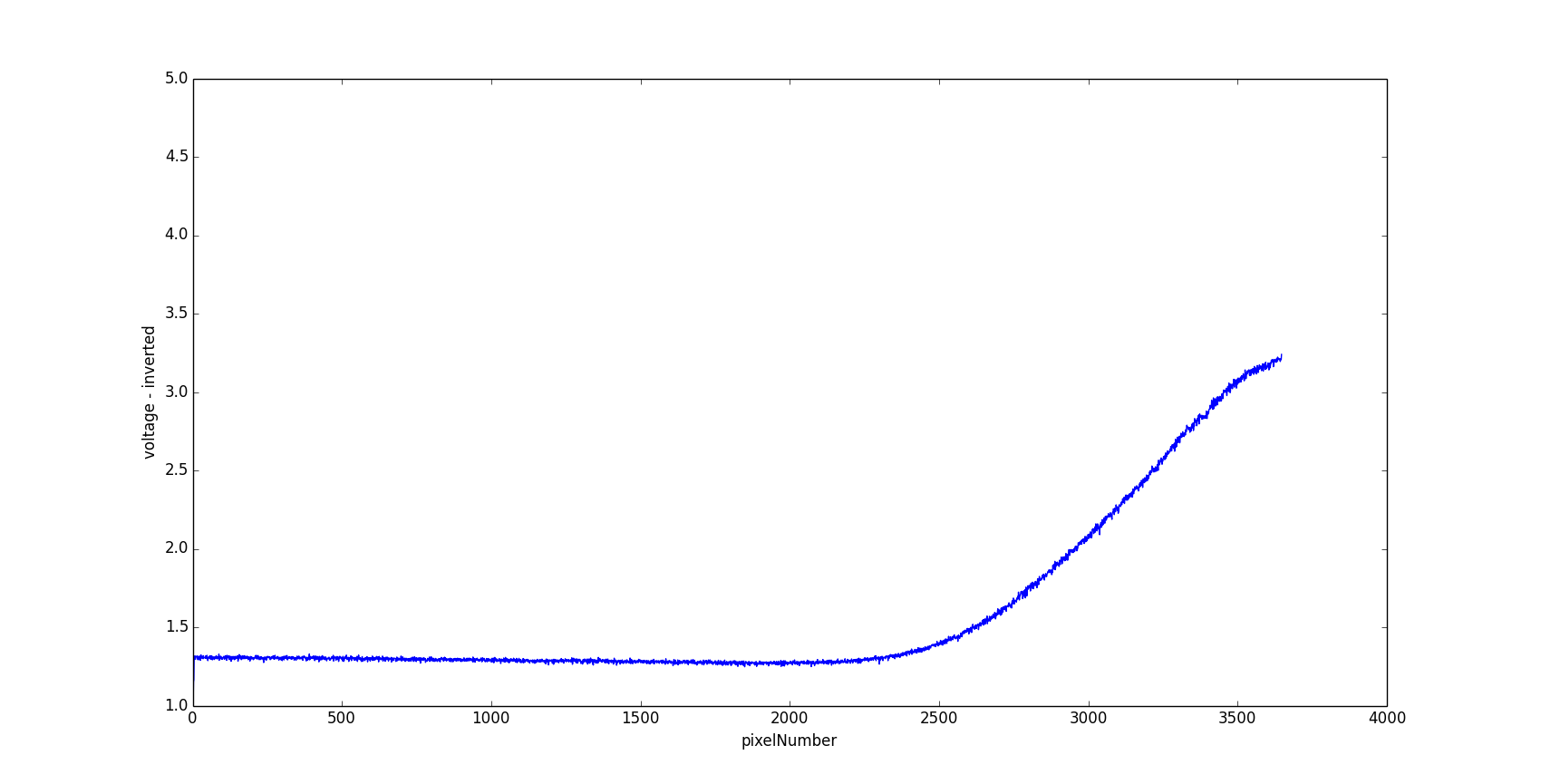
So, a little more progress with getting spectra to the raspi... I ditched the oscilloscope for this round... And here's some examples of actual data from the CCD transferred from the microcontroller through serial (to a PC for now...but it's written in Python and should port over to the raspi with no changes except the serial port hopefully)... I'll test this on the raspi soon..
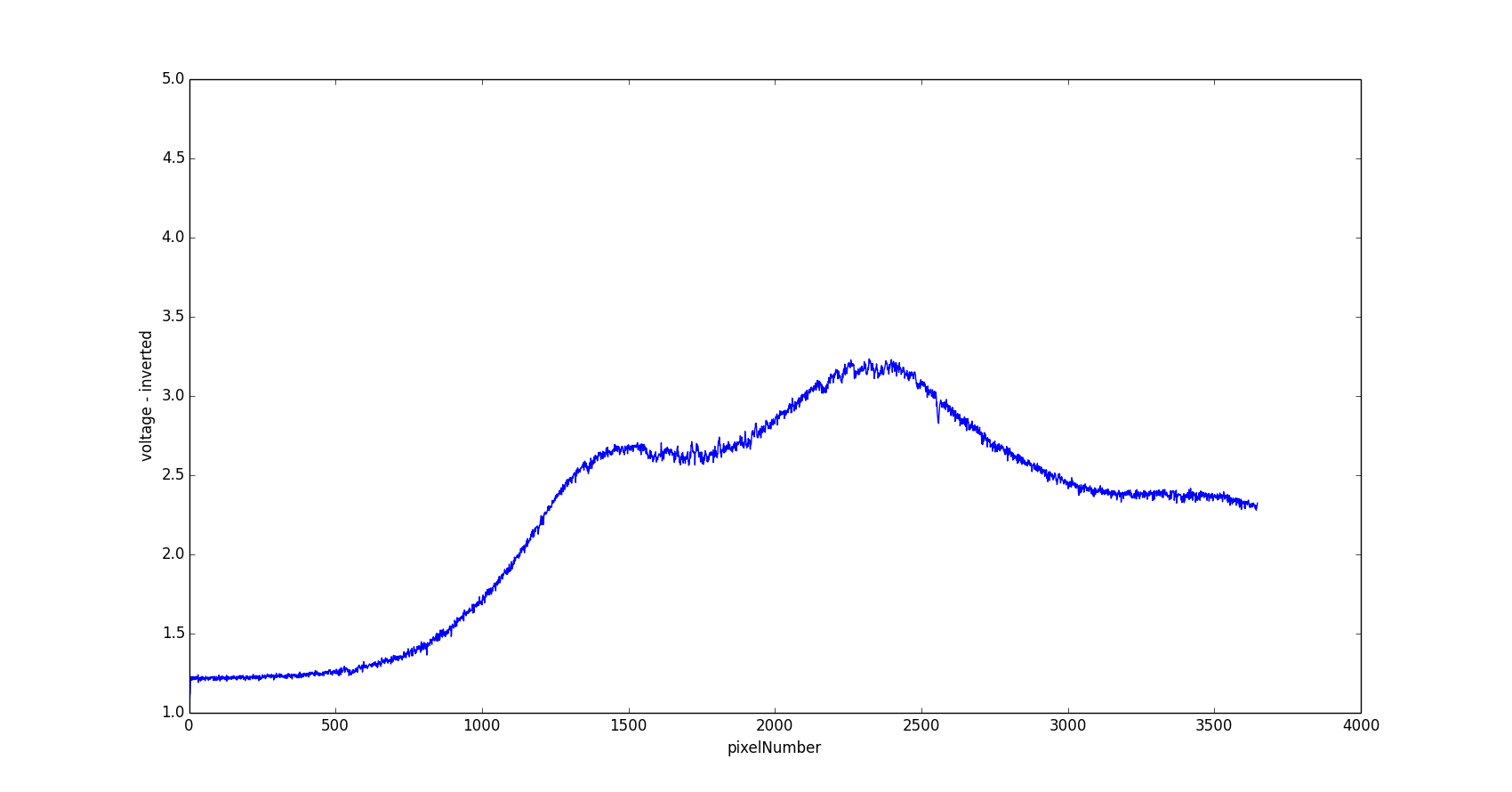
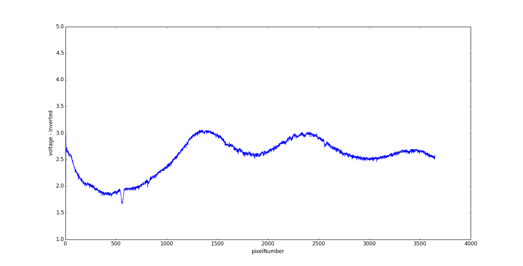
So, here's what matplotlib plots out from the serial data sent from the imagingBoard....
Here's the red filter...
![]()
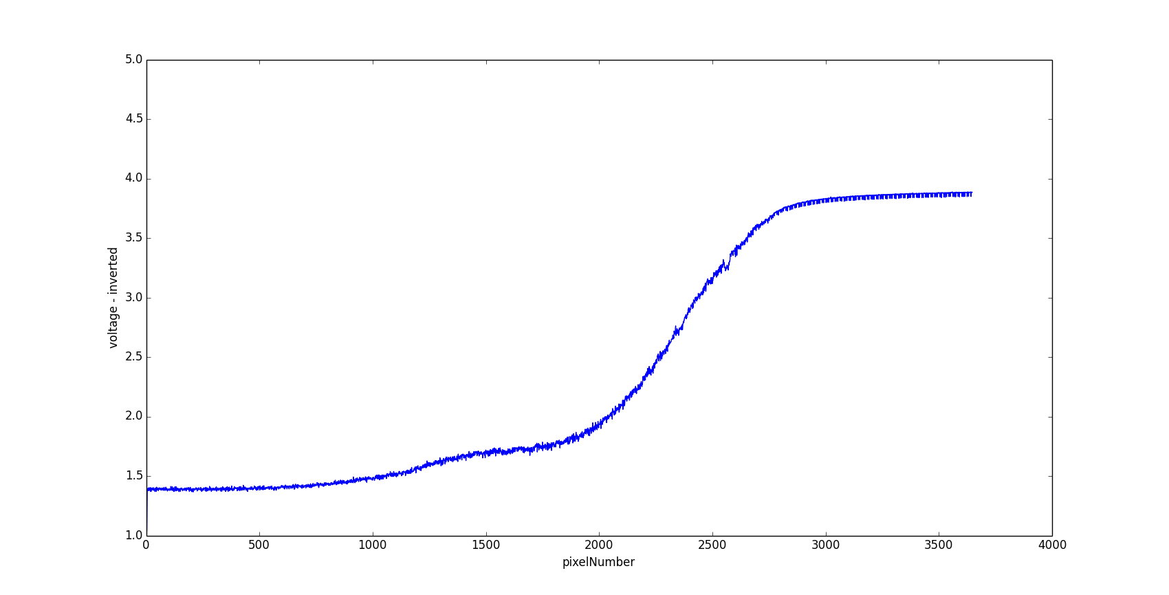
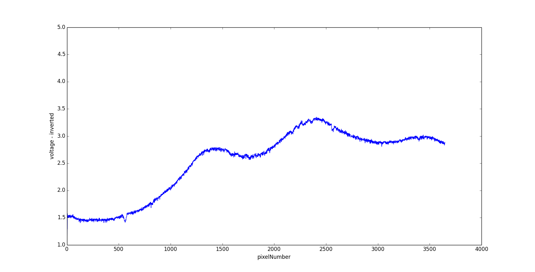
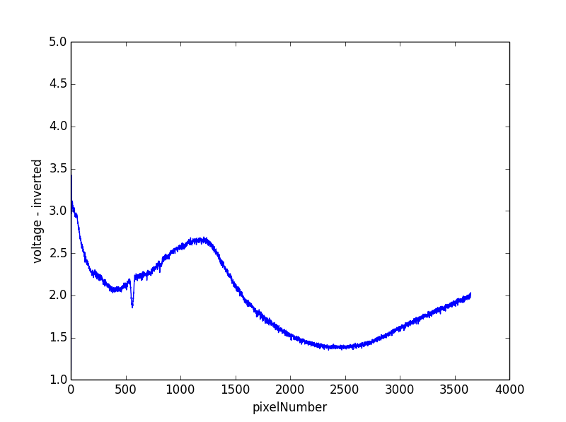
Orange..
![]()
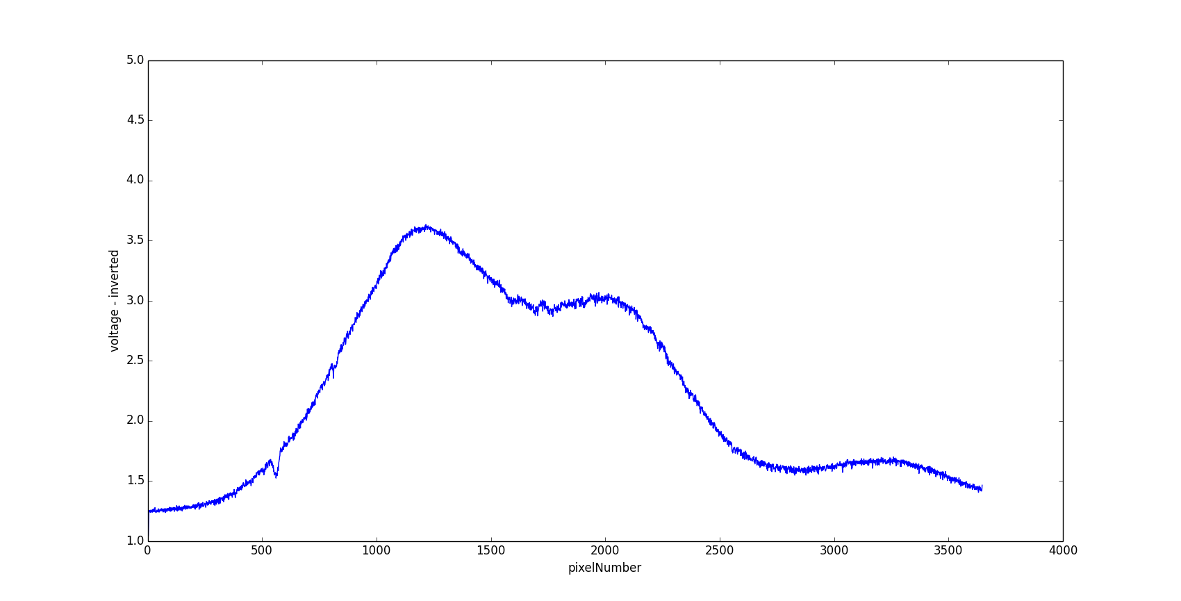
Yellow..
![]()
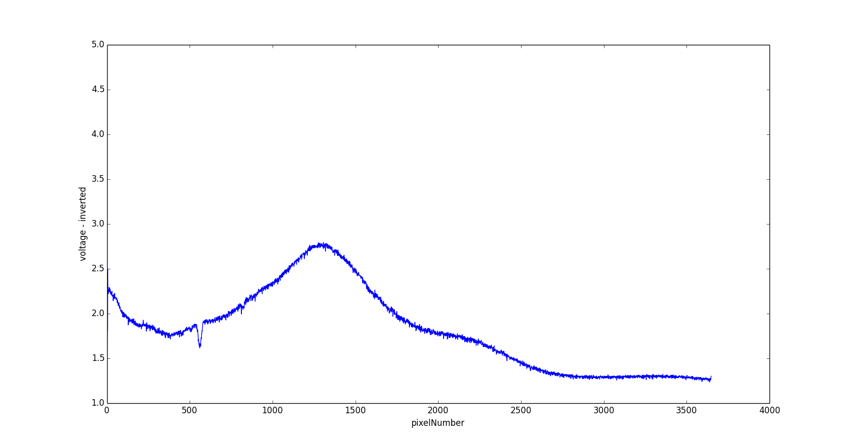
Brown..
![]()
Green..
![]()
Blue....
![]()
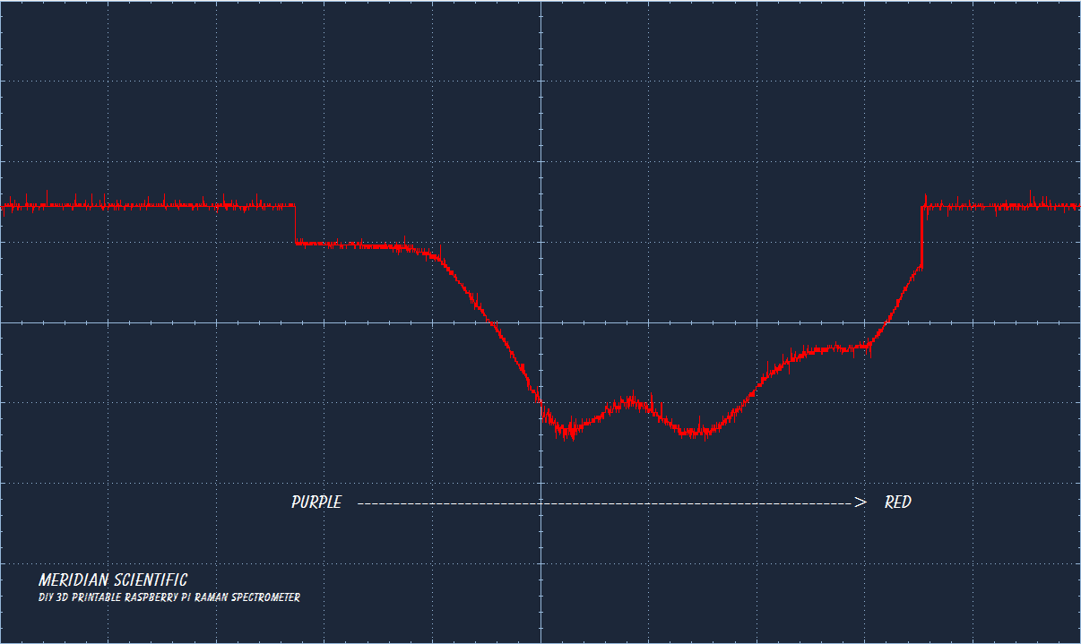
Purple...
![]()
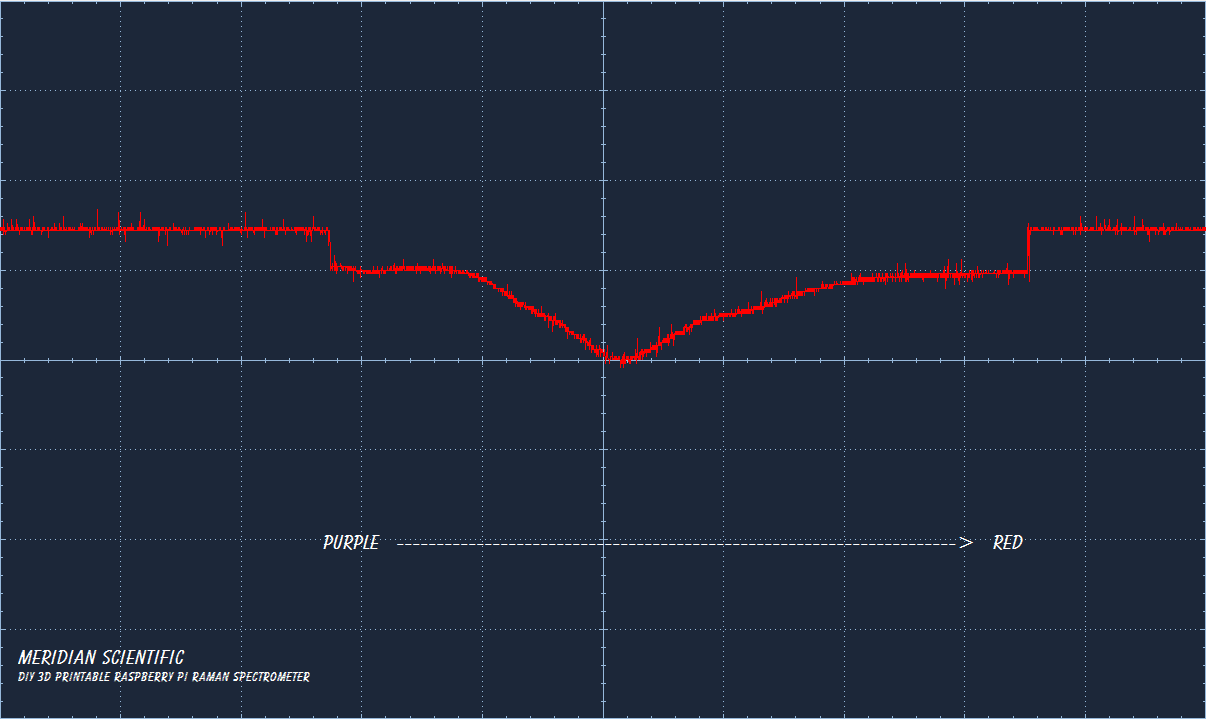
And purple sharpie for fun.. I saved this one at a different resolution sorry... ¯\_(ツ)_/¯
![]()
So.. the python code is up on gitHub... as is the code for the nucleo or you can look at the nucleo code on the mBed repo..
I'm just about finishing up this round of testing... and will be ready to move to the next phase soon.... Which will be finalizing the design for the printable spectrometer... I have been experimenting with locations and angles to place the light baffles, etc... and those will be included in the final design.. probably in more places than just the spectrometer.. During some previous tests I noticed a few hotspots for stray light around the beam splitter and the objective lens... So I will probably be paying attention to those areas and maybe others as well. I'll be experimenting with different methods.. When printing alot of these objects, and using the supports for overhangs...it occurred to me that the printer can do some interesting things with the plastic.. I might look into creating a surface on the inside that inhibits reflections, etc.. I don't know yet, but I'll be looking into it..!
![]()
-
A quick fun test with better filters..
08/18/2014 at 03:36 • 2 comments![]()
Ok, so I totally re-wrote the code for the CCD driving.. I actually totally removed the PWM driver for the ICG line and replaced it with a sort of state machine driven by the Shift Gate... So, now the firmware tracks the pixel position and what types of pixels it's reading so it can make decisions about what to do with the incoming data from the analog port. I haven't got so far as to actually buffer the data (right now it's dumping it to the serial port at 921600baud, which isn't quite fast enough).. I would like to store the data in memory and dump it every cycle, or when it's requested. I'll get there.. I need to write some python code to generate a graph based on that data too.. I'd love to get the remote rpc over serial working, but the mbed platform doesn't seem to support that on the Nucleo boards yet... I'll get there too... But for now, the filters I ordered from Amazon this morning (Sunday) arrived this afternoon (Sunday).. Amazing is what they should be called. Anyway, I took a minute to make these pics...I know I said I was going to try and capture real world pics of the CCD face to compare to each, but my camera just doesn't do that too well.. At least the one on my galaxy.. I'll try another camera when I can..Maybe my gopro will do better..
There's a lot of scope captures if you click the read more!
![]()
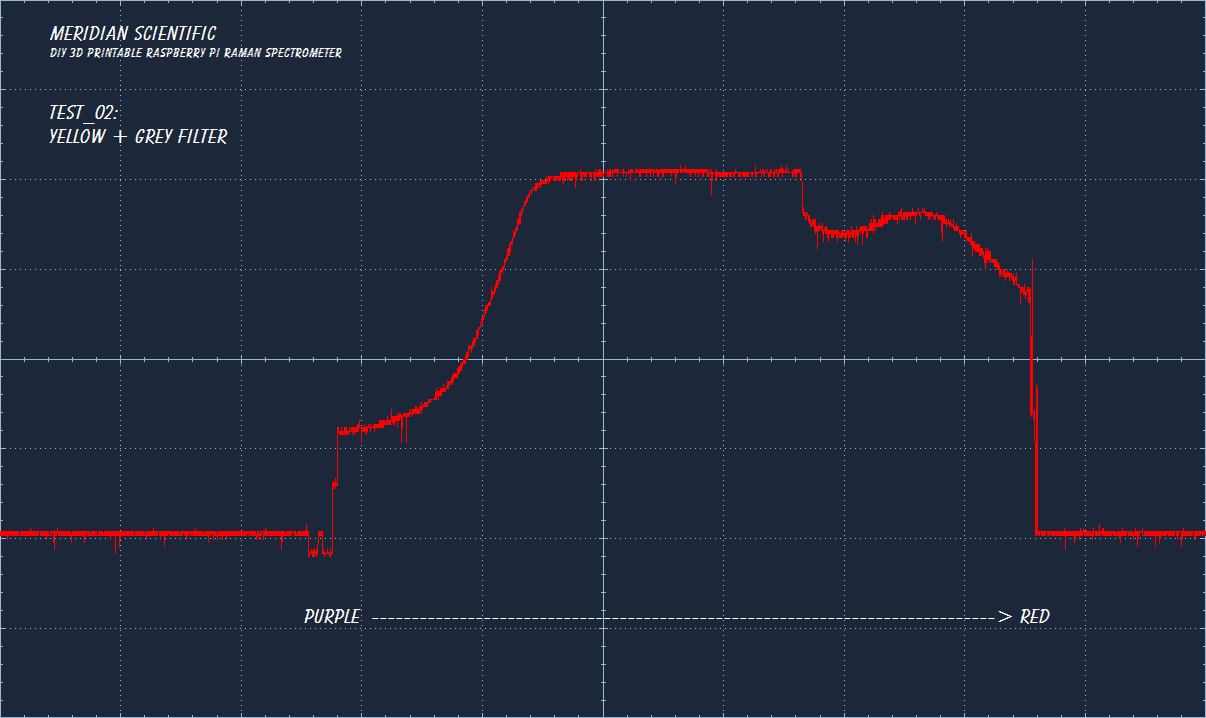
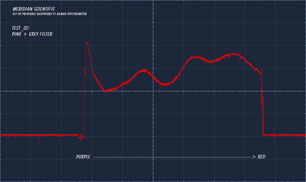
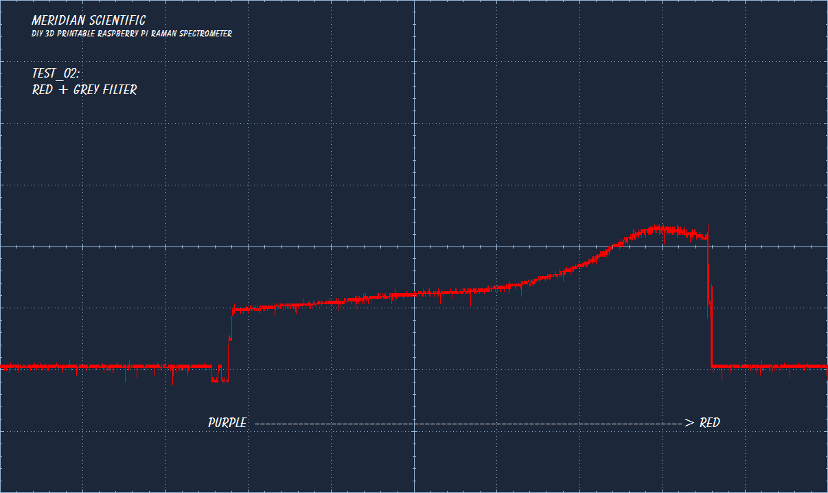
So, these filters are a LOT better.. Here's the results..
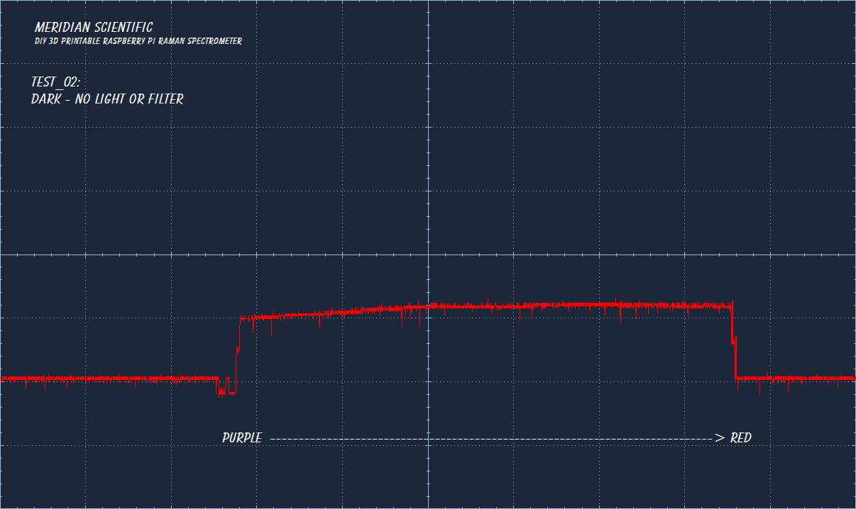
This is just the CCD at idle..no light source and no filters... I couldn't seem to get it dark enough.. =/
![]()
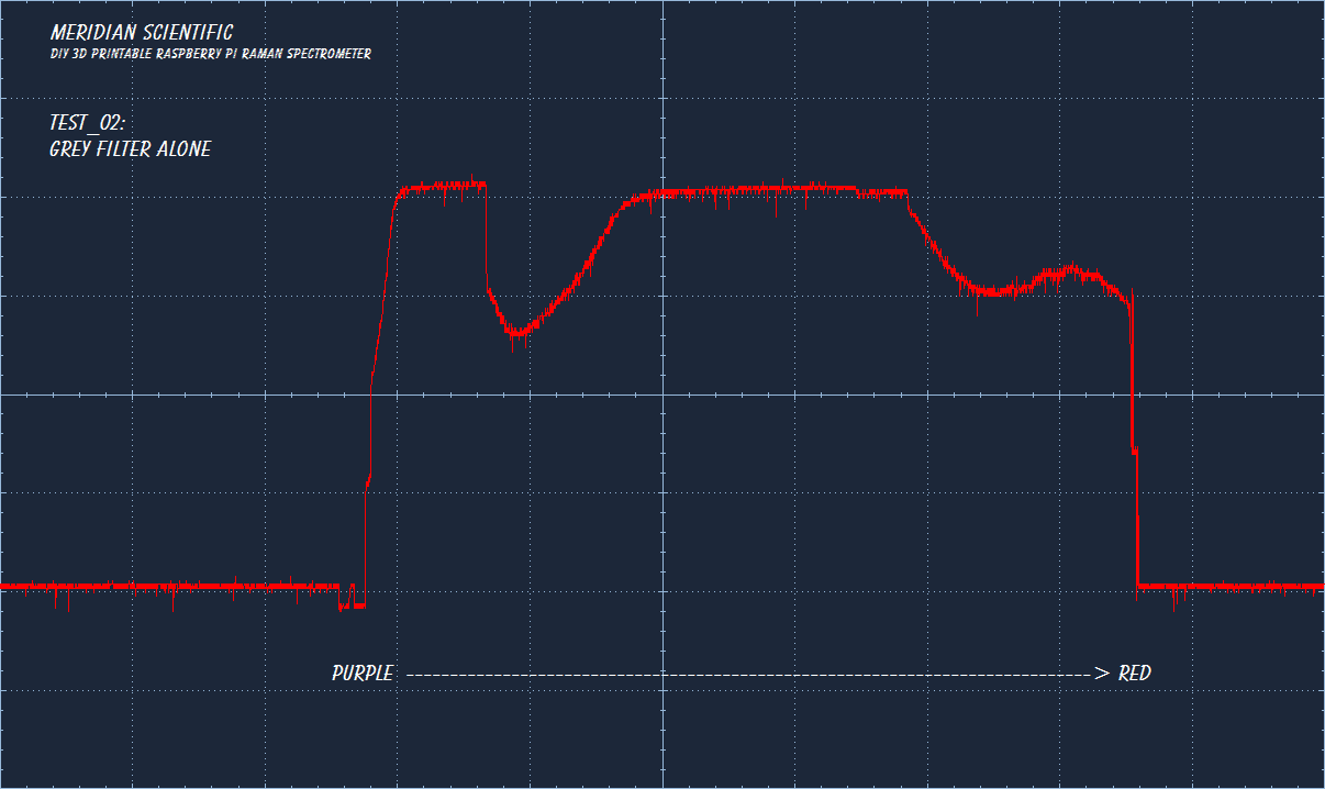
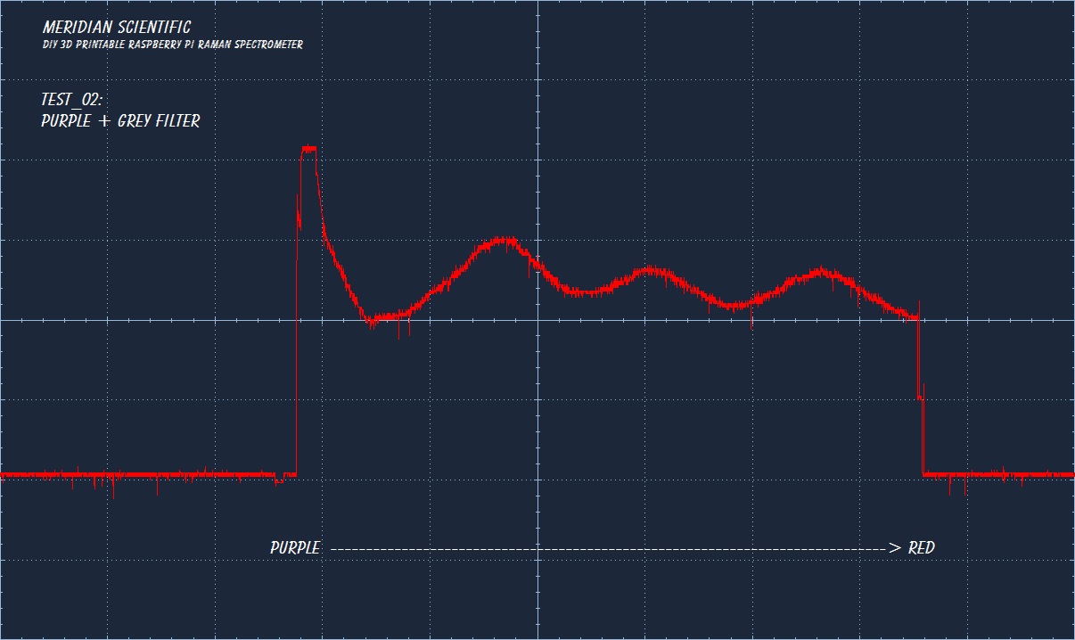
This is just the grey filter with the light source on... All the remaining captures have this grey filter added on because I couldn't get the light level low enough.. I could have adjusted the slit..but I didn't want to get that involved for this short test.
![]()
Here is purple...
![]()
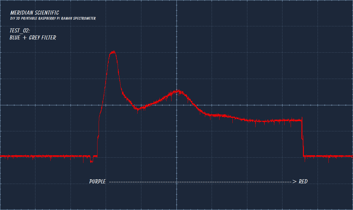
And then blue..
![]()
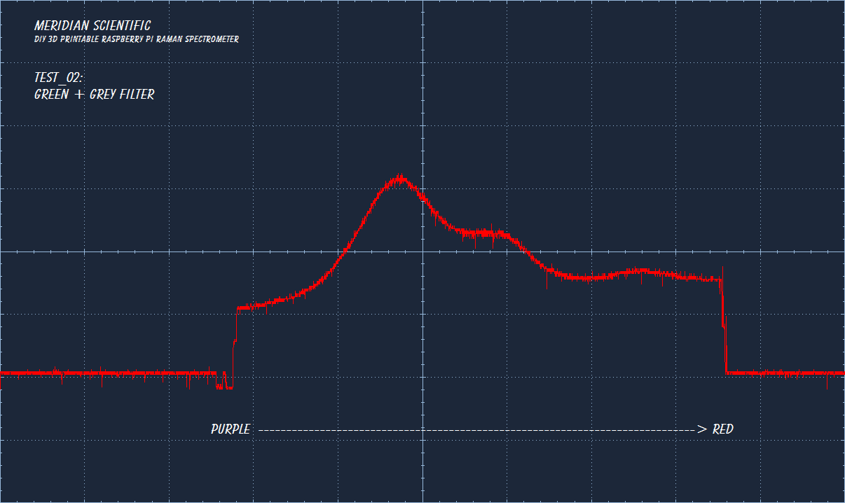
Next we have green..
![]()
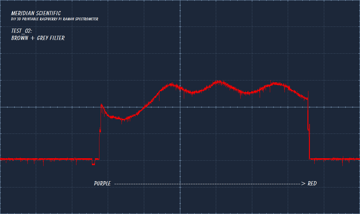
And perhaps brown..?
![]()
Then we'll go with yellow...!
![]()
And how about we throw in some pink..?
![]()
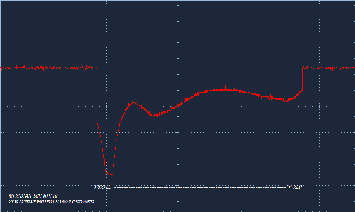
And finally we have red... :)
![]()
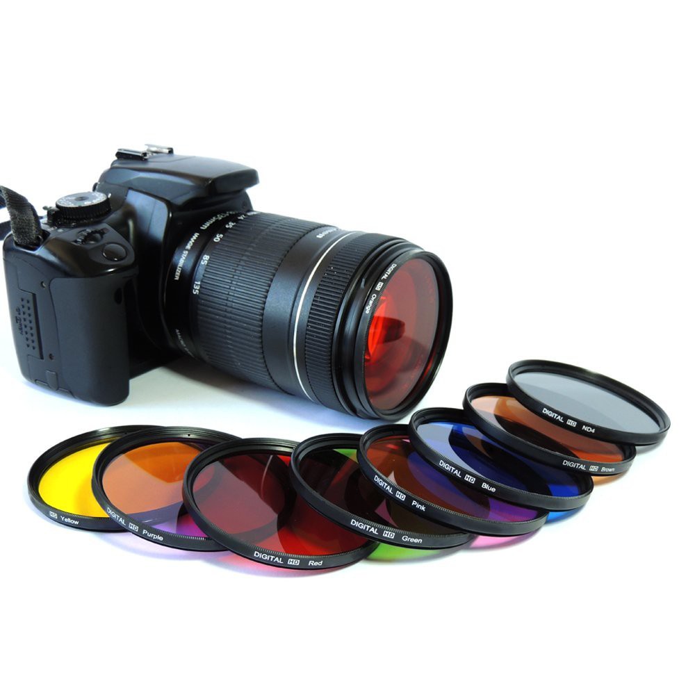
Here is a pic from Amazon of the filters used for this... Standard 52mm camera filters...
![]()
And just for good measure... and for those who would rather look here than go to the gitHub or mBed repo... The code I used for these... If anyone has any good suggestions on how to go about buffering the data, or getting the rpc over serial to work...I would love to hear it!!
#include "mbed.h" // *** BE SURE TO TEST BEFORE AND AFTER FOR 'IDLING'... CLEAR THE CCD EVERY OTHER FRAME TO TRY AND ELIMINATE NOISE BUILDUP //From <a href="http://www.ing.iac.es/~docs/ins/das/ins-das-29/integration.html">http://www.ing.iac.es/~docs/ins/das/ins-das-29/integration.html</a> //"Idling" vs. integrating //Charge from light leaks and thermal noise builds up on the detector between observations. If this charge is integrated by the detector, it may not be completely //cleared away by the clear cycle of the next observation. In that case, the observation will be contaminated by extra counts. (Often, this appears as a ramp in the //background leading up to a saturated region in the low-numbered rows.) //To avoid this problem, the detector is made to clear itself continuously between observations. This is called "idling", and is reported as such on the mimic. PwmOut masterClock(PB_4); PwmOut shiftGate(PB_8); InterruptIn shiftGate_int(PC_6); //PwmOut icg(PB_3); DigitalOut ICG(PB_3); //interruptIn icg_int(PB_3); AnalogIn imageIn(A0); //AnalogOut imageOut(A5); DigitalOut LED(LED1); Serial raspi(USBTX, USBRX); int masterFreq_period = 2; //microseconds int masterFreq_width = 1; //microseconds int shiftGate_period = 200; //microseconds int shiftGate_width = 100; //microseconds int none = 0; int veryLow = 1; int low = 100; int medium = 100000; int high = 1000000; int veryHigh = 10000000; double imageData; int sensitivity = none; int pixelTotal = 3694; int leadingDummyElements = 16; int leadShieldedElements = 13; int headerElements = 3; const int signalElements = 3648; int trailingDummyElements = 14; int pixelCount; int readOutTrigger; int state; #define readOut_Begin 1 #define readOut_ACTIVE 2 #define readOut_LeadingDummy 3 #define readOut_LeadingShielded 4 #define readOut_headerElements 5 #define readOut_signalElements 6 #define readOut_trailingDummy 7 #define readOut_integrationTime 8 #define readOut_IDLE 9 #define readOut_Finish 0 #define MV(x) ((0xFFF*x)/3300) float pixelValue[signalElements]; void error() { while(1) { LED = !LED; wait(0.5); } } void checkState() { if (readOutTrigger == 1) { // state = readOut_LeadingDummy; } switch (state) { case readOut_Begin: readOutTrigger = 1; state = readOut_ACTIVE; // ICG = 1; LED = 1; break; case readOut_ACTIVE: ICG = 1; state = readOut_LeadingDummy; break; case readOut_LeadingDummy: pixelCount++; if (pixelCount == leadingDummyElements) { pixelCount = 0; state = readOut_LeadingShielded; } break; case readOut_LeadingShielded: pixelCount++; if (pixelCount == leadShieldedElements) { pixelCount = 0; state = readOut_headerElements; } break; case readOut_headerElements: pixelCount++; if (pixelCount == headerElements) { pixelCount = 0; state = readOut_signalElements; } break; case readOut_signalElements: pixelCount++; // pixelValue[pixelCount] = imageIn.read(); // imageData = ((imageIn.read_u16() * 5.0) / 4096.0); raspi.printf("%4.12f \r\n", (imageIn.read_u16() * 5.0) / 4096.0); LED = !LED; if (pixelCount == signalElements) { pixelCount = 0; state = readOut_trailingDummy; } break; case readOut_trailingDummy: pixelCount++; if (pixelCount == trailingDummyElements) { pixelCount = 0; state = readOut_integrationTime; ICG = 0; } break; case readOut_integrationTime: wait_us(sensitivity); state = readOut_Finish; raspi.printf("---\r\n"); break; case readOut_Finish: state = readOut_IDLE; wait_us(sensitivity); LED = 0; ICG = 1; break; case readOut_IDLE: if (ICG == 1) { ICG = 0; state = readOut_Begin; } break; default: break; } } int main() { ICG = 1; LED = 0; pixelCount = 0; readOutTrigger = 0; state = readOut_IDLE; masterClock.period_us(masterFreq_period); masterClock.pulsewidth_us(masterFreq_width); shiftGate.period_us(shiftGate_period); shiftGate.pulsewidth_us(shiftGate_width); raspi.baud(921600); wait(0.5); shiftGate_int.rise(checkState); raspi.baud(921600); while(1) { wait(1); } }![]()
-
The Joy of Specta
08/16/2014 at 13:38 • 7 comments![]()
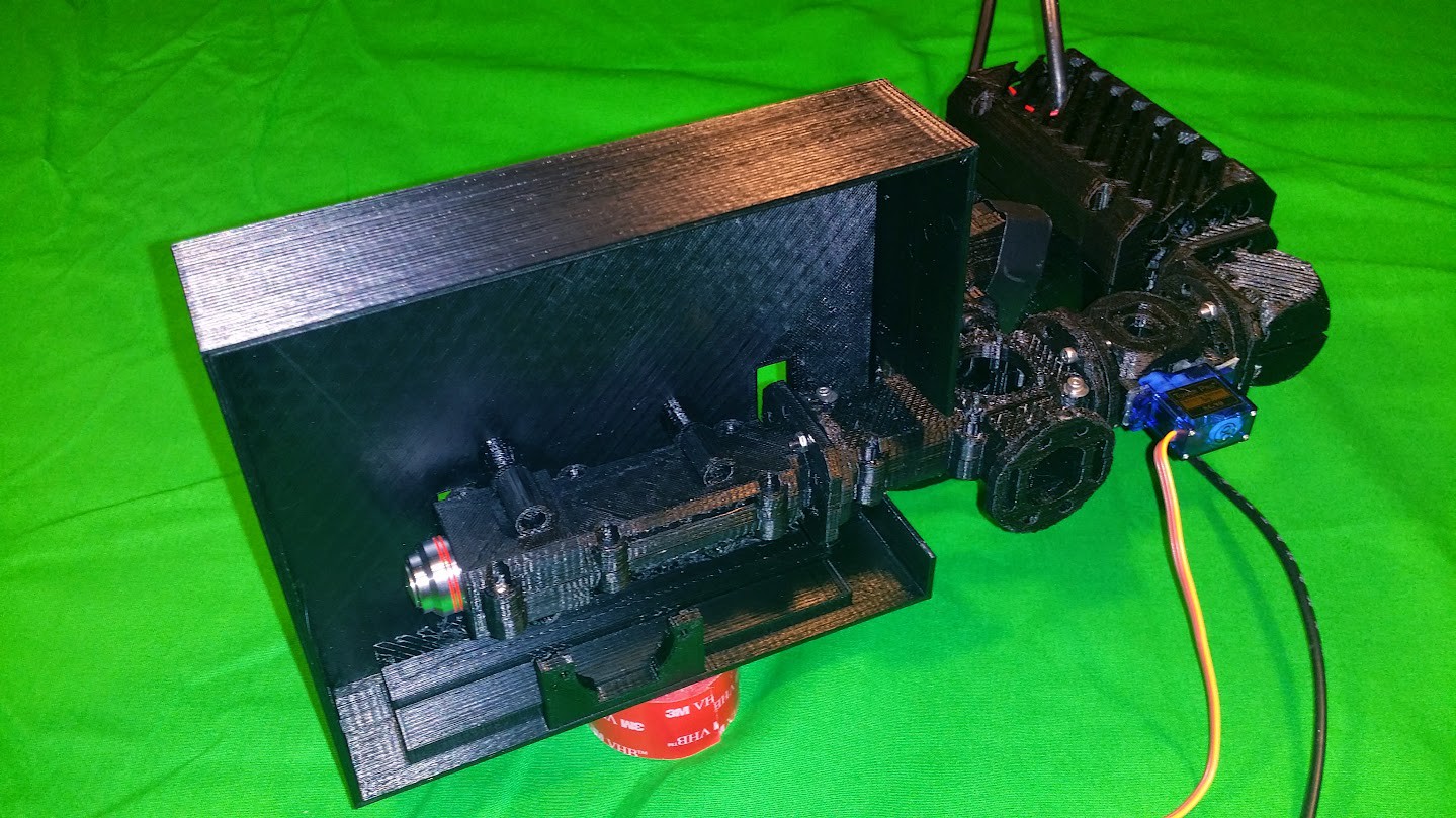
So.. Here it is... Success.. This is just a test rig, and it's not raman spectra (yet).. but this is my linear ccd setup, with the Crossed Czerny-Turner Configuration..using the optics from Edmund Optics.
![]()
This is using the 3D printed parts I threw together a day or so ago... and I have been waiting for them to finish printing for a couple days now..... Well, that wait is over and my first round of tests have some results..
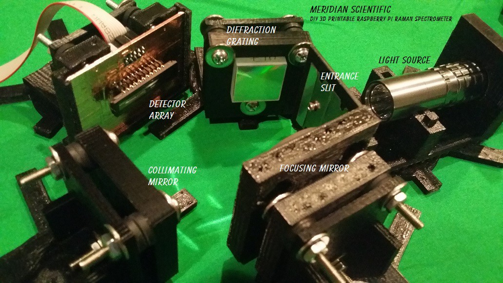
Here is an overhead view of the test setup.. For this simple test, I'm using an LED flashlight.. Nothing fancy to start with.. Mind you these are just throwaway stands I whipped up for this test..they won't go into the final design...
![]()
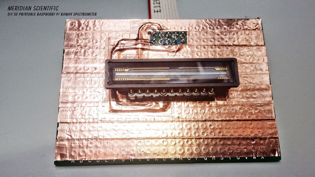
Here's my CCD Board that I'm using for this test.. I haven't added any ADC since I haven't started that part yet, I'm just using a scope for this round.. and I'll be using the 12bit ADC in the Nucleo for the next round.. I'm going to give the mBed 'Fast ADC' library a try for starters... So again, nothing fancy..
![]()
A little closer up... This is the Toshiba TCD1304DG.. Same (except for packaging- this one's ceramic not plastic) that the Ocean Optics, and other major brands use.. I got it on eBay for 15 bucks. They still sell new for around $22..
![]()
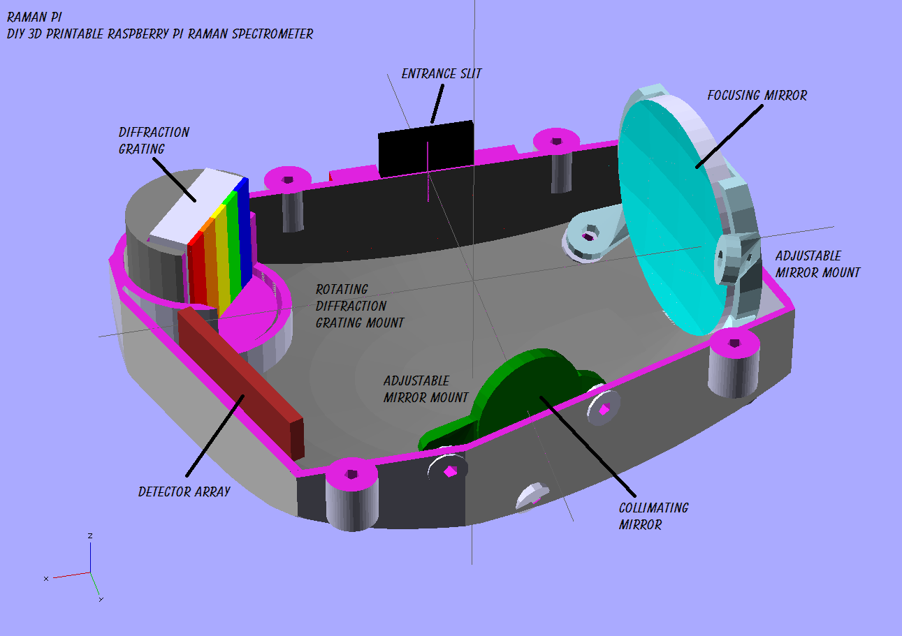
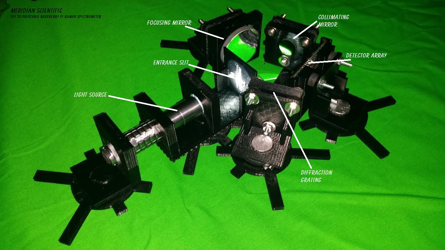
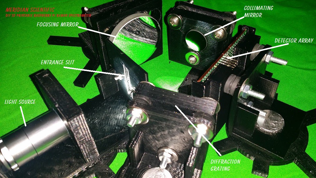
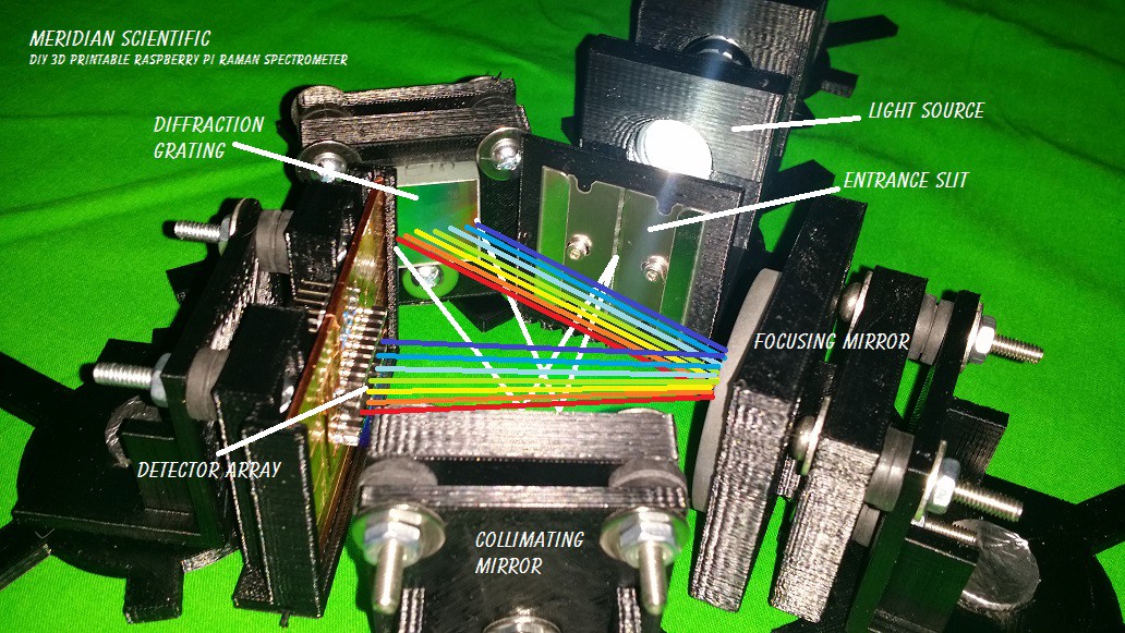
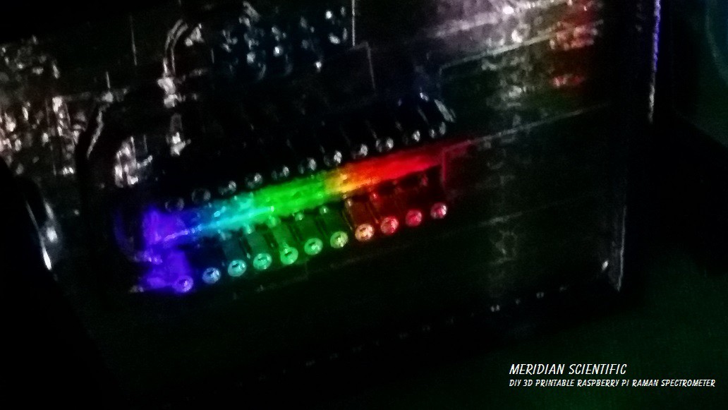
Here's a nice close up.. The light comes in from the left with the flashlight, goes through the entrance slit which acts like a vertical aperture where it's trimmed down and projected as a vertical line on the collimating mirror.. as a result the light is directed into a column onto the diffraction grating in the lower center of this pic.. it's then reflected and diffracted into a rainbow onto the focusing mirror where it's focused across the detector array(linear CCD- Toshiba TCD1304DG)...
![]()
A little closer shot with a slightly better view of my twin razor blade entrance slit and the diffraction grating..
![]()
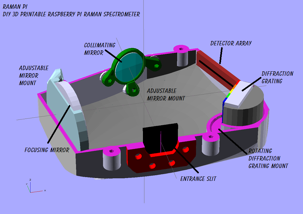
Another angle and illustration of the light path...
![]()
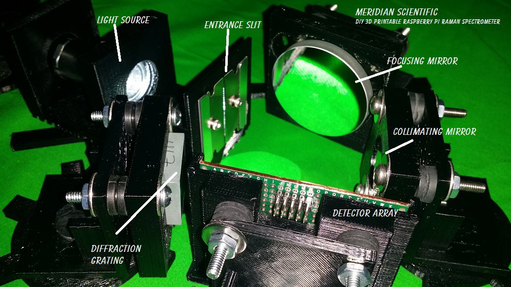
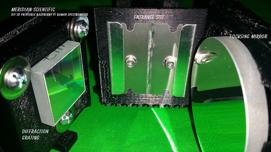
A really nice closeup of the twin razor blade entrance slit, and both the diffraction grating (left), and the focusing mirror(right).
![]()
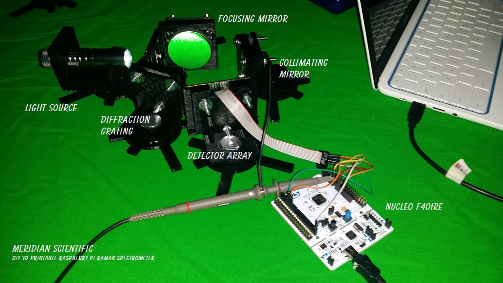
Here's the whole setup with the nucleo hooked up to the Toshiba CCD...
![]()
One more angle for good luck.. ;)
![]()
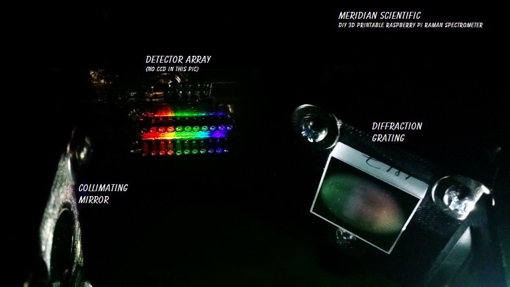
And what you've been waiting for... First spectra... I didn't have the CCD installed here because I wanted to align everything first.. But there it is... (You might notice the notch in between the blue-green and the purple where the LED flashlight doesn't emit much light..)
![]()
Another angle of the same, with the grating and collimating mirror visible..
![]()
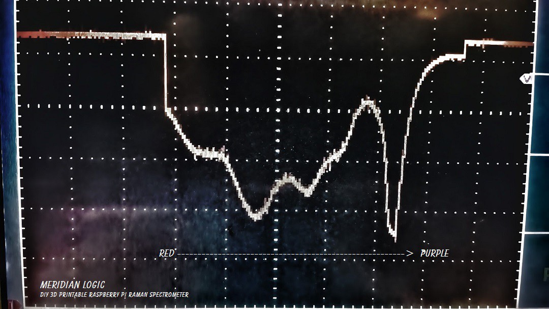
And there's the scope... Bad photo but it clearly shows the notch I mentioned above between blue-green and purple! And you might also notice how little noise it's producing.. =) I might also note, that the scope pictures are inverse values.. So what you see is essentially upside down. In this first picture, you can really tell the LED had a lot in one band of purple not much blue and quite a bit of green and yellow, and about half as much red...
This one goes from red on the left to purple on the right and the others from the PC are the opposite...
![]()
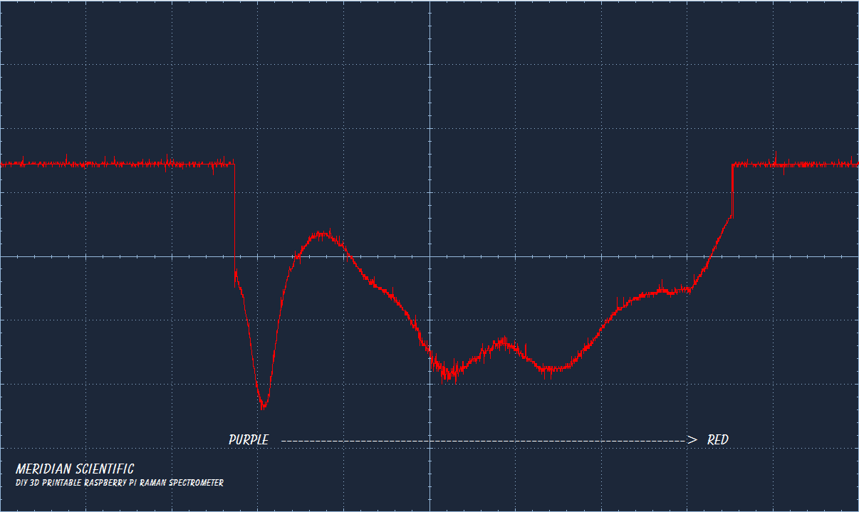
Ok.. so here are some better captures from the PC software...
First up... The straight LED light from the flashlight...
![]()
Next up is a piece of clear plastic colored with a purple sharpie..
![]()
Next we have another piece of plastic colored this time with a yellow sharpie..
![]()
And the same but this time it's green...
![]()
So, there you have it... the first round of result with some good spectra! Next step is to get a little more serious with my code... start using the numbers from all of this in my 3d models and hopefully print some stuff up to test with... And more importantly...something better than an LED flashlight to test with... and some better color filters than sharpie colored plastic...not sure why I didn't think ahead on that one...And especially here... if anyone has any input or suggestions...or just friendly comments and criticism...I'd love to hear it all!
![]()
-
First Serious Spectral Test Setup
08/15/2014 at 08:18 • 1 comment![]()
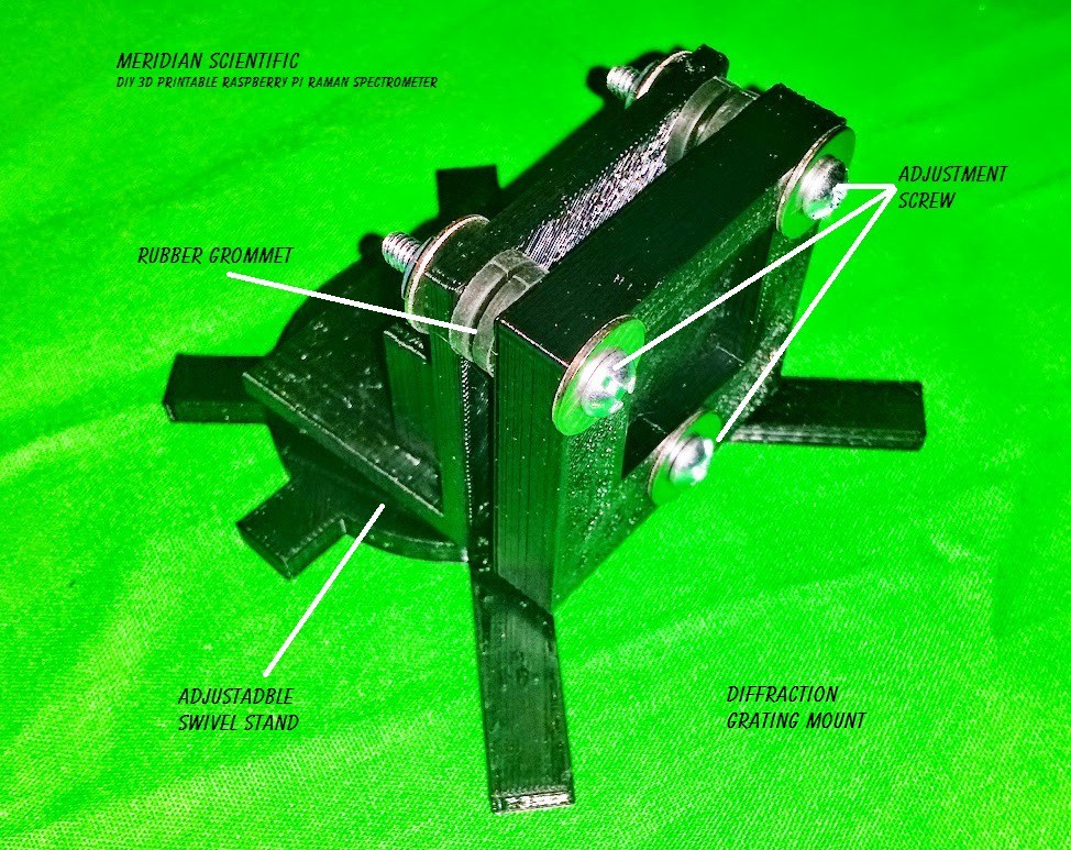
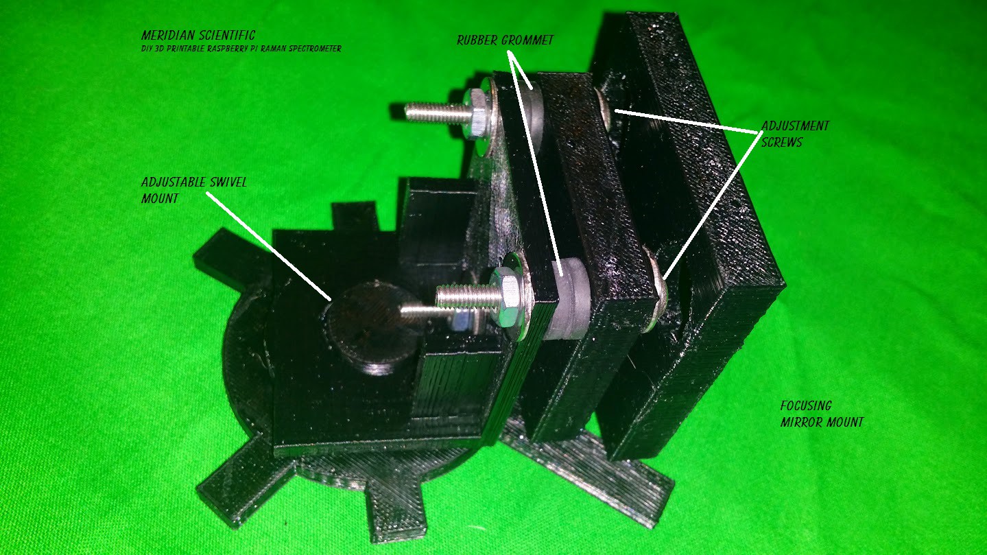
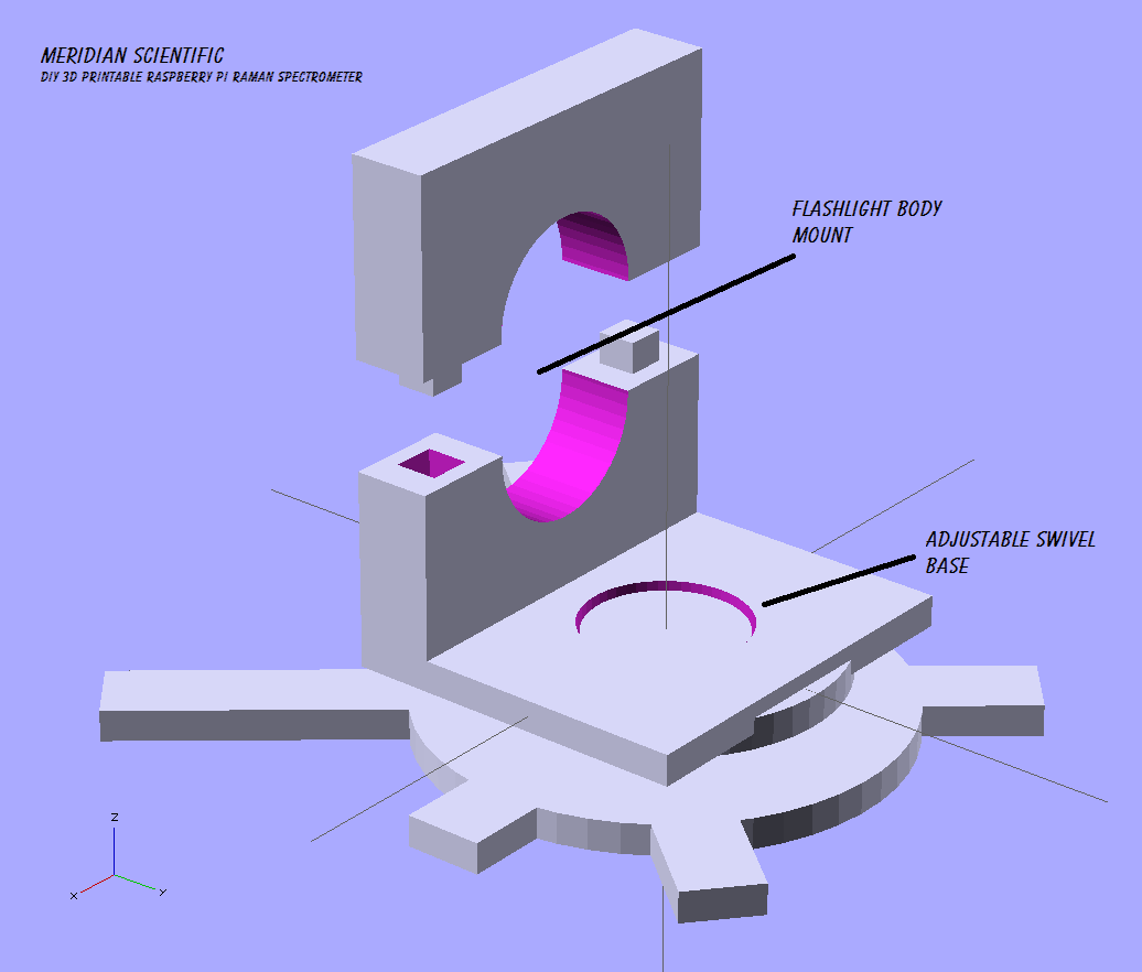
So, in the process of designing the spectrometer portion of this system.. I want some real world examples before going out on a limb and trying full scale right off the bat... In this spirit, I have designed some small throwaway test stands for the optics that will allow me to arrange them in whatever configuration I want. Each stand has a similar base which can freely rotate, and has three adjustment screws which will allow me to make minor adjustments to the mirrors, etc.. For people building their own version, you'll probably not need to print or make these... this is mostly for my testing for the design..
Some of the mounts are still printing right now, but here is what I have so far...
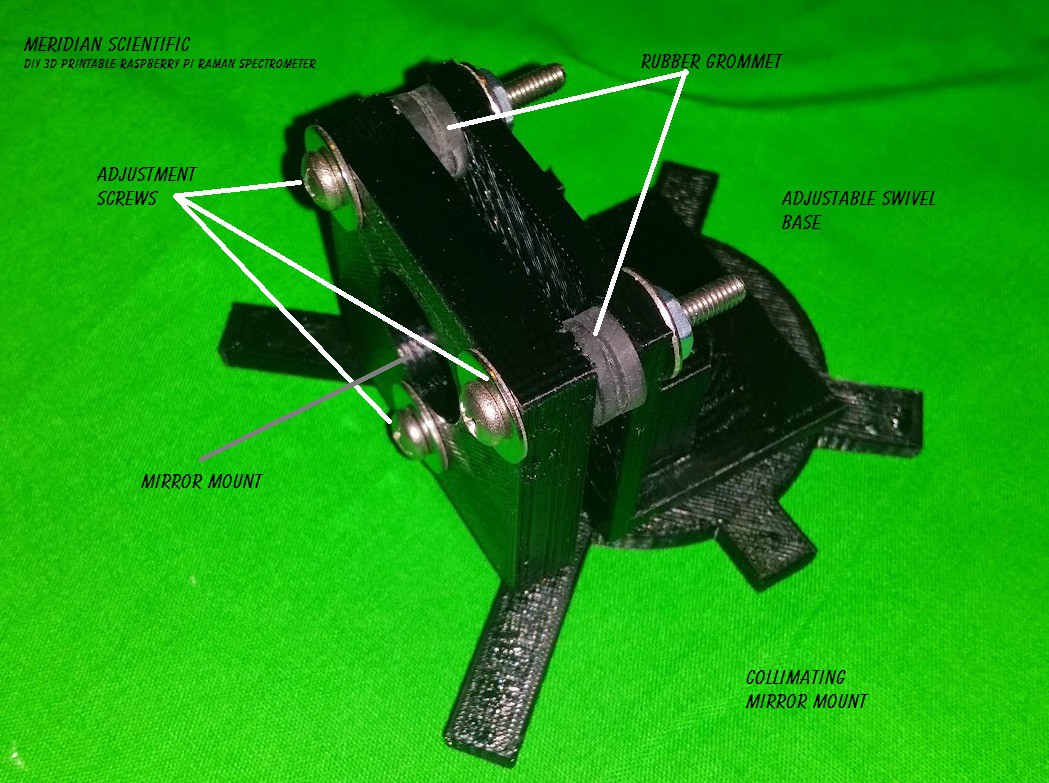
This is the back view of the collimating mirror stand.. As you can see, it swivels and there are three screws to allow for directional adjustment...
![]()
And the front of the collimating mirror stand...
![]()
The diffraction grating stand..
![]()
The focusing mirror stand... A little larger because this mirror is 50mm in diameter...
![]()
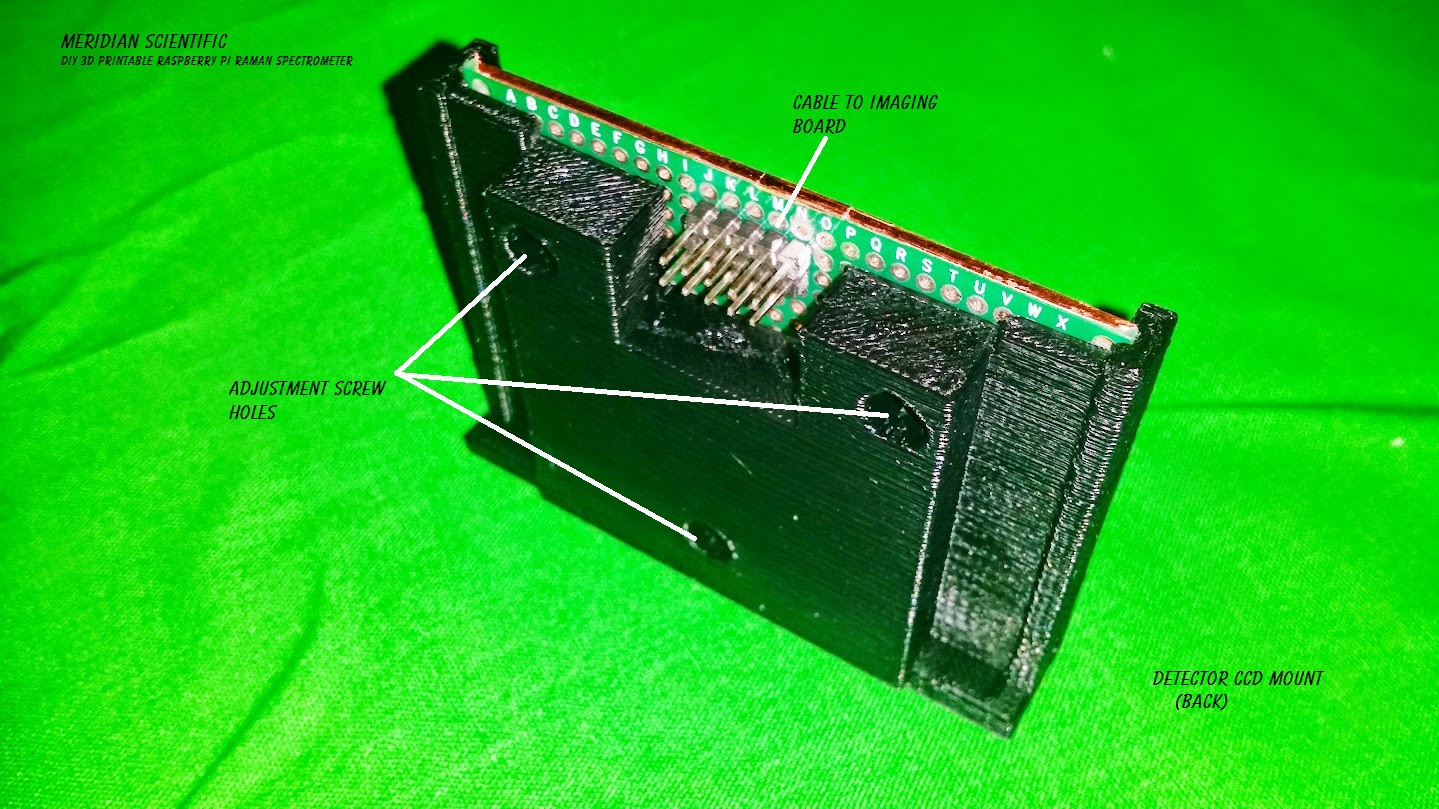
Here's the back of the mount for the linear CCD... The PCBoard just slides into it...
![]()
And a front shot (with no CCD in the socket at the moment)...
![]()
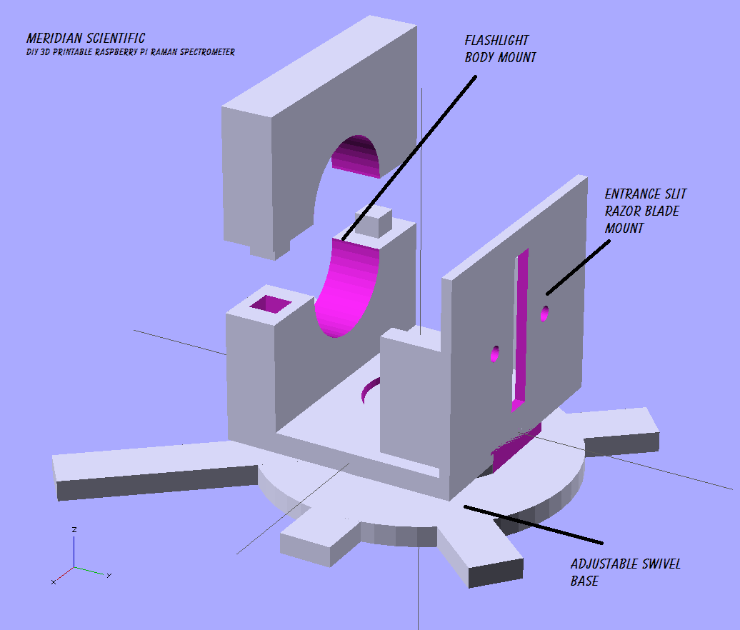
I'll post an update when I have the rest of the objects printer... for now, here's the renderings...
Here is the front end of the stand that holds the light source...For this test I am using an LED flashlight since I am only trying to align and test everything...I am just going for a regular spectra like a normal spectrometer so it won't include the laser until my next tests when I go for the raman spectra...
The front half of this also has the verticle support for the entrance slit... which in this test will be two razor blades screwed to the stand to allow for adjustable width..
![]()
And the rear half of the light stand...
![]()
Hopefull all goes well, and I will post very soon some photos with results! I'll be capturing the spectra hopefully with both a camera..(I might use my gopro) and the oscilloscope..!
As always, the files for these objects are all located in the gitHub repo!
![]()
-
It had to happen some time...3D Printer problems...
08/13/2014 at 13:54 • 5 comments![]()
It had to.. Murphey's Law.. Well, I have printed quite a bit on the new Da Vinci 3D Printer... I actually really like this thing...
![]()
But it is out of commission for the moment.. Sputtering prints... I ran through all the normal cleaning procedures... Long story short... .. A combination of problems.. Many failed attempts and a lot of wasted time and plastic...I think I have it under control...It is currently 5 hours and 8 minutes into a print with 3 hours and 2 minutes remaining....and the print looks good so far.
If anyone is interested, I can share a couple lessons learned...
Update: Thanks for the interest! Here's what I learned..
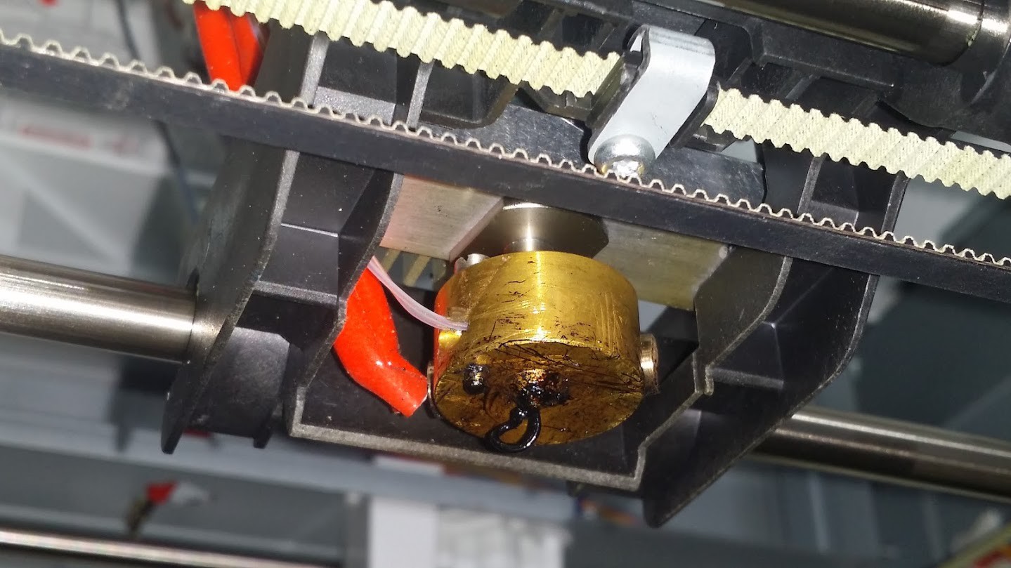
It started out with the printer just having little spots here and there where there'd be sputters and inconsistent flow.. That didn't always ruin a print.. but it was annoying, I'm sure most people are familiar with that.. The major problem came when the extruder started making the clicking thumping sound...that sound it makes when the drive gear slips and strips the plastic... It only seemed to do it at certain points in the print.
So, the nozzle was pretty dirty... (worse than this actually because I forgot to take a pic of it)
![]()
So, I started with the normal suggested cleaning... Wire brush... Broke out the little wire cleaning tool provided with the Da Vinci.. Heated the nozzle, poked the wire in there scrubbed around.. Looked good.. Tried it again.. nope. Same problem and more wasted time and plastic.
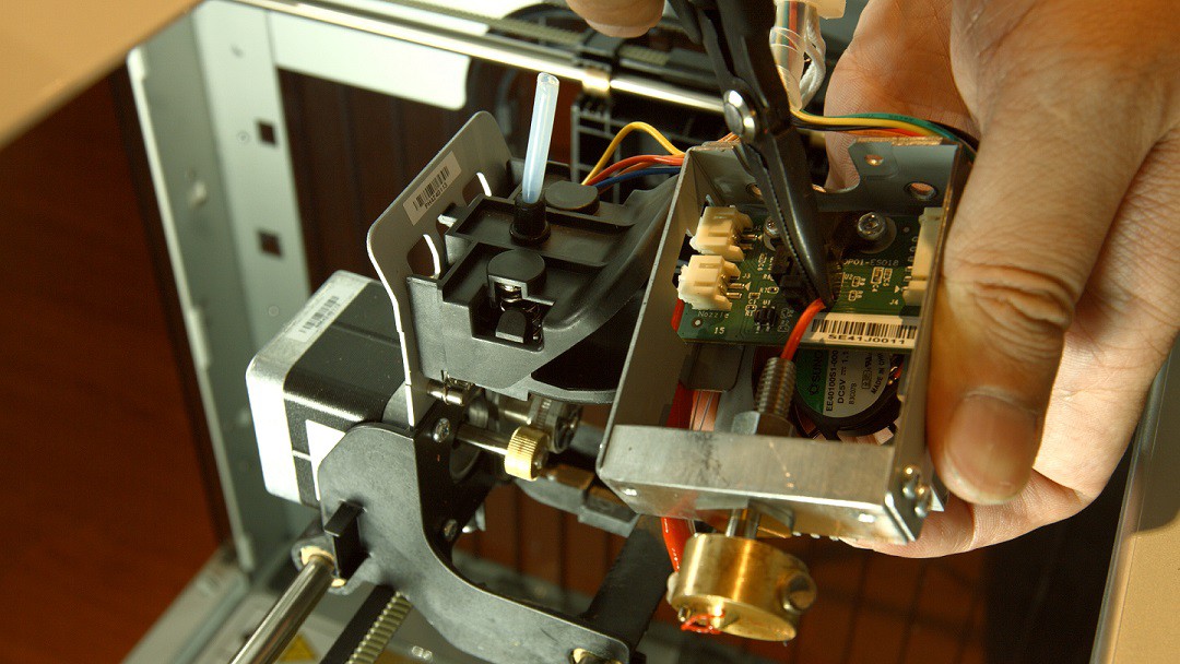
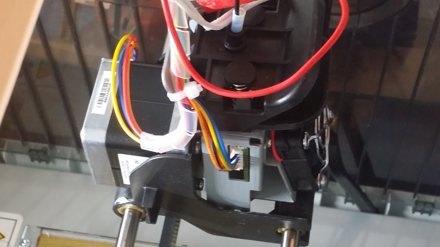
Next round.. This time I decided to go a little further.. The Da Vinci is pretty cool for a few reasons.. The extruder is mounted with a quick release...(which is a double edged sword that I will get into in a bit.).. I pulled the cable to the extruder and hotend.. then removed the extruder..
![]()
I cleaned more.. even cleaned the optical encoder wheel they have on the extruder gear..pretty cool.. This time it was going to work for sure.. .. right?
Nope. When I put the extruder back in, and connected the cables..powered on the printer.........I went to the menu option to inset the filament......the nozzle temperature was reporting 10 degrees Celsius.. It was heating..I found that out the hard way.. But the thermocouple wasn't sending.. So I pulled it out again, tested the resistance.. nothing... Huh? How did I break a wire? The thermocouple surely couldn't have just gone back that quickly..and I don't think I am that clumsy...the wires are pretty substantial...
![]()
Tried again.. nope.. another meter... dead battery.. Ugh.. Lucky I had a third because that meter showed some resistance.. Murphey's Law in full effect..
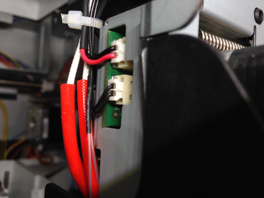
So... I trace the connection.. the top half of the thermocouple goes to gnd and the case of the machine.. the other goes to the top pin on the big connector with the black wire..I do a reading and get resistance at that connector.. So, the extruder assembly seems good.. I put the whole thing back together and connect it up.. still nothing with the sensor.. In my brain, this means something is up from the connector to the main board.. And again.. I don't think I'm that clumsy.. So I try an old trick that works with cheap connectors sometimes.. I tweak the pins in the connector so they're just angled enough that they are guaranteed to make connection...
![]()
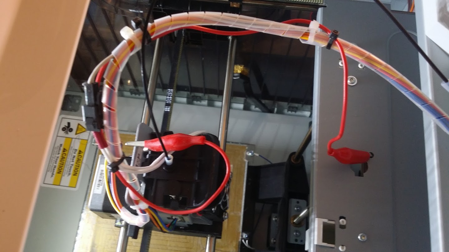
Put it back, this time I get a reading... Good. I push on the extruder to make sure its seated.. reading goes to zero. AGH.. Long story short, after a couple rounds I started noticing that it wasn't the connector after all. It was more to do with how the extruder was seating.. So, I whip out the multimeter...continuity between the metal frame of the extruder to the metal frame of the printer was iffy... Weird.. So I decided to try an alligator clip from the extruder to the frame... Bingo... a reading every time and movement and bending the wires made no difference..
![]()
After all of that. and running through another pretty thorough cleaning... I ran white filament through, kept running it until it was clean... then removed it.. then cleaned it again.. making sure to heat the nozzle the whole time.. I ran the wire from the top down through the whole thing.. getting every little particle out.. I didn't want to try the blowtorch thing because I'd hate to try and rebuild this thing.. especially in the middle of a project. I then put the black filament back in, ran it through for a bit..
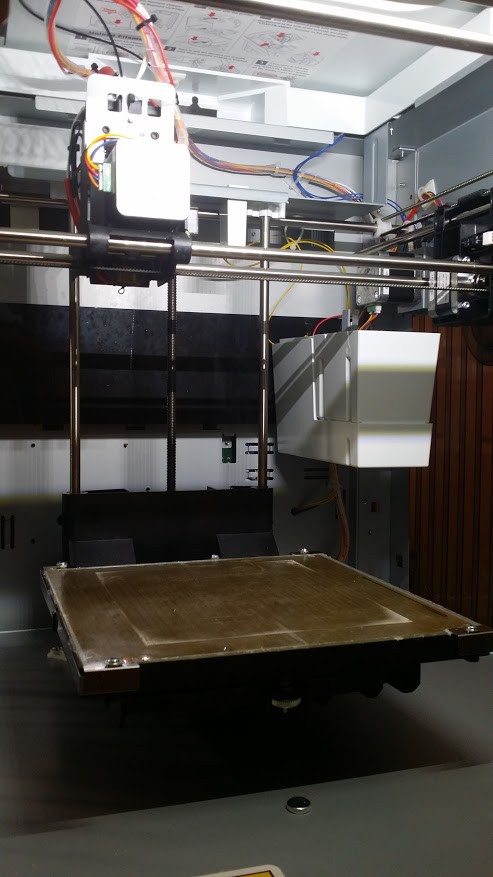
And the next step is what I think made the most difference.. The bed on this printer is mounted at three points with springs and thumb screws..
![]()
The printer automatically calibrates by moving the bed up and having the nozzle touch three corners of the bed to make an electrical connection.. if the bed is out of whack more than 5mm on any corner it fails.. I tried the calibration (and you really have to make sure the metal tabs are clean) and it failed several times.. I adjusted since my front right corner was too low...until it passed..
![]()
So, it finished the print after over 8 hours... and it looked great.. Couldn't be happier.. Lesson learned.........1. you get what you pay for.. $500 is super cheap for a 3D printer, and this one does a great job for that price.. And I don't regret buying it... However, it's not perfect, and you will have some minor but not insurmountable problems.. 2. Bed leveling is not fun and being out of what can cause major issues. 3. 3D Printers need better technology for extruders and hot ends... I want a printer I can dump scrap into the back of, and it prints wonderful parts in an array of colors and doesn't take forever.. Ha.. I can dream. 4. I'm going to investigate further, but I think part of the issue might have been the filament.. I'm not sure how long it takes this stuff to get soggy, and I'm not sure how much of a problem that really is...and the major issue with the Da Vinci is the filament... you can only use theirs, and it's like double the cost of normal filament...and you can only buy ABS.. I know there are hacks, but I haven't had time... and from what I read, XYZ plugged that hole by using encryption.. sad.. But that's the world we live in..
But ultimately, it seems to be back on track and printing great parts!
![]()
Hope that was worth the wait... =D
![]()
ramanPi - Raman Spectrometer
The open source 3D Printable Raman Spectrometer using a RaspberryPi and easy to find off the shelf components..