fl@C@
fl@C@-
Spectrometer Optics
08/12/2014 at 11:51 • 0 comments![]()
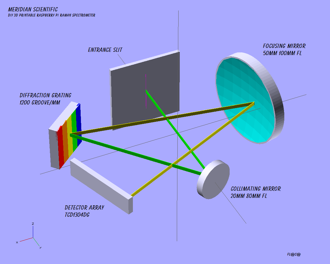
So.. after a lot of reading.. a lot of thinking... a lot of experimenting.. playing around and tough decisions.... I have what I think might be the candidate for the actual spectrometer.. This is using the optics I just received from Edmund yesterday. I have a quick rendering of where the entrance slit, mirrors, grating and detector are in relation to each other.. I still need to fit this into a box that will fit in with the rest of the components..
But... here's a sneak peak..
![]()
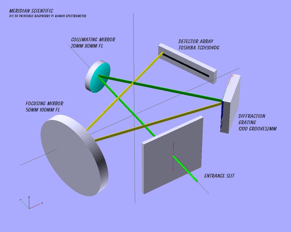
Another view....
![]()
As always, I'd love to hear what you think!
![]()
-
CCD Noise Considerations
08/12/2014 at 07:40 • 2 comments![]()
I've been working on getting things tied up with the CCD... I wrote some more sophisticated code to control the CCD, code that allows me to control the exposure and integration times.. It's amazing how sensitive the Toshiba chip is.. I covered the face of the chip with a 1/8" peice of black plastic, then sat a peice of foam over that...and the CCD could still respond quite well to just the reflected light from me lifting my arm two feet away.. All that with very little noise still..about the same amount as my scope captures in my previous post..
So, sources of noise.... This document does a great job of outlining sources of noise in a CCD.. There's shot noise, Reset Noise, Output Amplifier Noise, White Noise, Clocking Noise, Dark Current Noise, Surface Dark Current Noise, Bulk Dark Current, Photo Response Non-Unifiormity(PRNU).. As a side note, apparently these chips are fairly sensitive to IR and prolonged exposure to IR will cause degradation and will increase the PRNU..
There is a lot of give and take with this stuff. I am mainly going to focus on a couple types of noise for this project at this stage.. And I am going to start with Dark Current Noise..
Dark Current Noise
Dark current arises from thermal energy within the silicon lattice comprising the CCD. Electrons are created over time that are independent of the light falling on the detector. These electrons are captured by the CCD's potential wells and counted as signal. Additionally, this increase in signal also carries a statistical fluctuation known as dark current noise. CCDs can be cooled either with thermoelectric coolers (TECs) or liquid nitrogen to reduce this effect. Ideally, the dark current noise should be reduced to a point where its contribution is negligible over a typical exposure time.In the transfer region, a dark current occurs under the transfer electrode, and its magnitude is proportional to the signal transit time of the CCD analog shift register area: i.e., it is proportional to the product of the clock pulse cycle and the number of shift register transfer steps. Therefore, the dark signal increases as the operating speed decreases. Furthermore, the dark signal output doubles with approximately each 8°C increase in ambient temperature. As previously described, as the operating speed decreases and the ambient temperature rises, the dark signal increases and the dynamic range of the video signals decreases.
![]()
Doubling the dark signal output for every 8degrees Celsius is nothing to ignore... This document has some good information.. And I think cooling is probably a good idea.
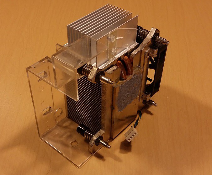
I did some quick testing with cooling options for the CCD. So, I tried a few combinations of CPU heatsinks and a 12v peltier device.
The first test I did was with a small CPU heatsink with a small fan... I attached a medium sized 12v 40mm peltier hot side to this heatsink .. The fan and the peltier were connected to the 12v output of a 230w ITX power supply.
![]()
The surface of the peltier never reached lower than 52 degrees Fahrenheit. I tried the same heatsink above but on the cold side and a larger heatsink on the hot side.. The heatsink on the cold side, after about 20minutes dropped to about 54 degrees.. Meh..
So, I moved to the next option.. A heatsink I removed from an old PC I had laying around.. Same config pretty much as above..Hot side of the peltier to the heatsink and so on..
![]()
This heatsink was able to help reduce the surface of the peltier to around 32-36 degrees Fahrenheit.. Pretty big improvement, but still not quite what I was hoping for...
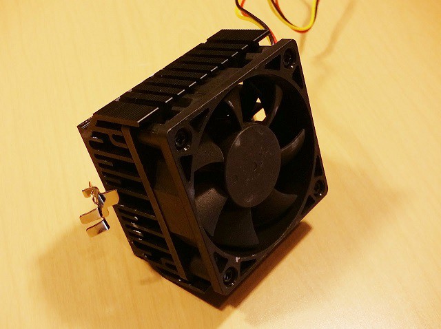
I then, pulled out the crazy...if not impractical try.. This monster.. =D
![]()
Ok, so this thing got the surface temperature down to -6 degrees Fahrenheit.. That's -21deg C.. Wow. Same peltier device, same voltage, etc.. Big difference.
I've read that going to -50C isn't uncommon...a lot of systems use liquid nitrogen.. I am waiting on an eBay order for some various peltiers and I will see if I can eek any better results with a smaller heat sink.. I had a thought about stacking or staging them, and apparently there are people doing it.. I still need to look into that, but it doesn't appear to be much more efficient. I will also know better what I can fit into the case after I complete the spectrometer design.. (The optics arrived today so I can get that going!) As far as physical contact with the CCD chip itself to transfer the heat, I am thinking that I will mount the chip on a dual sip socket so it has about 13mm clearance under it and between the pins.. and a 12.5mm square copper bar will fit under and wrap to the underside of the PCB into a sort of coil..like a heatpipe... The peltier will sit on this flat coil.. I am waiting for parts for that..hopefully that idea works..it seemed the simplest thing to reproduce for people since you can buy the copper bar on amazon pretty cheap.
>edit: See comments below.. I need to do my homework on the 'heat pipe'... :)
![]()
-
1st step to spectral success
08/09/2014 at 13:18 • 1 comment![]()
First off - you're going to want to hit the read more tag on this one if you're interested in this project...all the good stuff is toward the end... :D
![]()
![]()
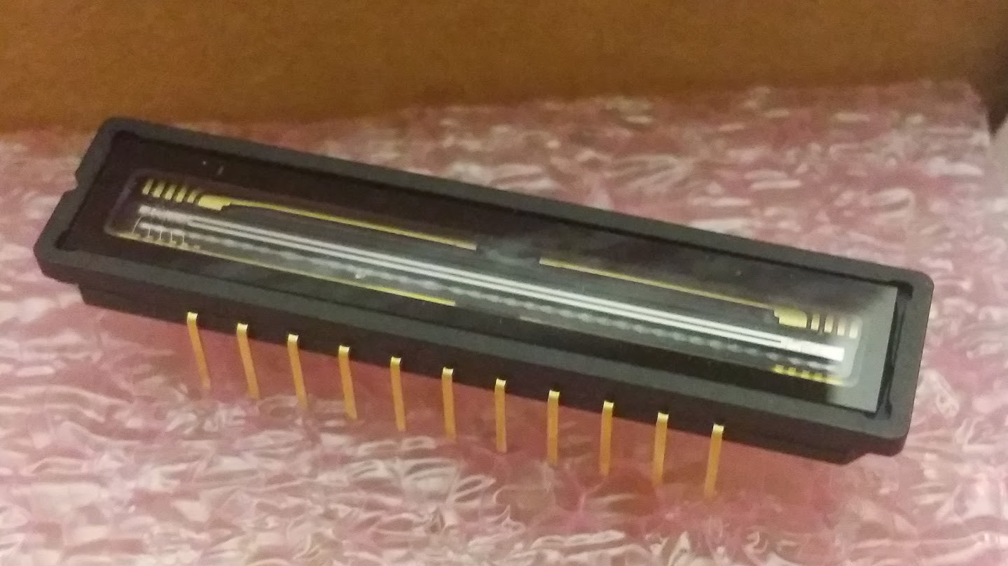
So... I got my delivery of the third Nucleo board from Mouser... A Toshiba TCD1304DG from eBay... and a few other parts that I ended up not needing...So, with that.. I set forth to get the CCD Array working.. I feverishly poured over every document I could find anywhere.. and there isn't much.. I tried to see if I could locate a development board, a prefab'd board that I could dissect...maybe a barcode scanner.. something... Nope. Nothing for less than $300 and certainly nothing I could get this month because of shipping..
A little backstory.. I had been mildly concerned about driving the CCD...how I was going to do it, etc.. I have no experience with CCDs, etc.. A bunch of searching turned up what I have said in previous build logs.. It seems the Toshiba and Sony chips are the most common used in spectrometers... the Sony chip is out of production... eBay has them, but it's literally weeks for delivery.. and someday they'll probably be gone.. not to mention they are mostly refurbished...... So, anyway.. Weeks have gone by that I've been flipping out stressed over getting the CCD up and running... I've been reading as much as possible, thinking, working on other parts of the project and so on.... Last night, I spent HOURS figuring out focal lengths and mirror angles for the spectrometer portion... and made a leap and ordered some optics from Edmund.. ok.. So, today..I figured.. I have enough parts to at least make an attempt with the CCD..
I sat down.. and went over some documents that I had previously found.. A site that sorta helped me gain my confidence and think maybe I had something to fall back on was this one.. Unfortunately he uses the Sony ILX511 and I couldn't get ahold of one for weeks.. After much searching, I decided to go to the source... The mBed website.. :) And after searching for 'ccd' there, one turned up! The mBed Pinscape_Controller is a project by Mike R. on the mBed site.. And oddly enough, he's using the TAOS TSL1410R which I did a writeup on thinking I might be going with that until I received some friendly advice from Marvin in the comments section notifying me that that chip was a bad option because of integration times... Thanks Marvin!!
So, after reading the writeup that Mike R had on the mBed site... I decided that maybe.....I would skip the ADC and other hardware that is normally used to control the CCD...and just drive it straight from the Nucleo.. There's only three clock signals... and the Nulceo has like 4 PWM controllers.. I figured it couldn't hurt to try... :D
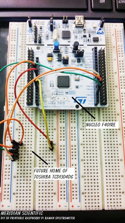
So, I sat down with the datasheet for the Toshiba TCD1304AP (which is almost identical to the DG except for packaging)... And study, study, study for a few hours... Then I built up the nerve..So I started off with just placing the Nucleo on a protoboard (it doesn't insert due to the dual rows of pins) with some jumpers to where the CCD would be...
![]()
Then I starting some coding.... I wrote a quick program to generate the three clock signals that are required by the CCD..
This is my super simple starter test...emphasis on test since I know this isn't a great way to set up timing..but it worked for this proof of concept..
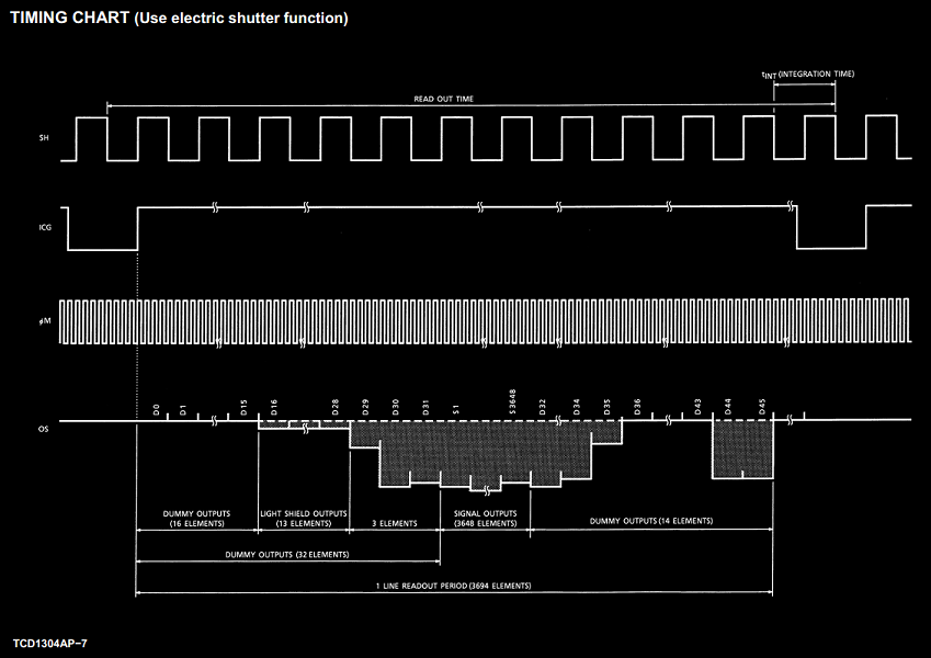
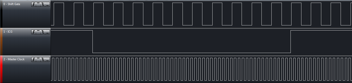
#include "mbed.h"

PwmOut shiftGate(PB_8);
PwmOut icg(PB_3);
PwmOut masterClock(PB_4);
AnalogIn imageIn(PA_0);
DigitalOut led1(LED1);

int main() {
    // set the masterClock
    masterClock.period_us(2);
    masterClock.pulsewidth_us(1);

    // set the shiftGate and have it start 15us after the masterClock - this will sync the clocks up so the shiftGate is going high just as a clock cycle is going high
    wait_us(15);
    shiftGate.period_us(20);
    shiftGate.pulsewidth_us(5);

    // set the ICQ clock and have it start 82.76ms after the shiftGate - this will sync the clocks up so the ICQ is going low slightly before the shiftGate is going high
    wait_us(82760);
    icg.period_us(80000);
    icg.pulsewidth_us(79990);

    // do something while it's having fun..
    while(1) {
        led1 = !led1;
        wait(1);
    }
}
Here is the timing chart from the datasheet for the TCD1304AP.... I needed to match this as closely as possible.
![]()
My first attempt wasn't good...nowhere near what I needed to have...but it was at least generating three PWMs..
![]()
My second attempt was a little closer... But still waaaay off.. But it was getting a lot closer.. Not quite, but a little.
![]()
At this point, I was ready to insert the CCD in and try out my clocks...
![]()
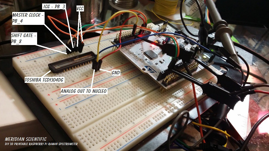
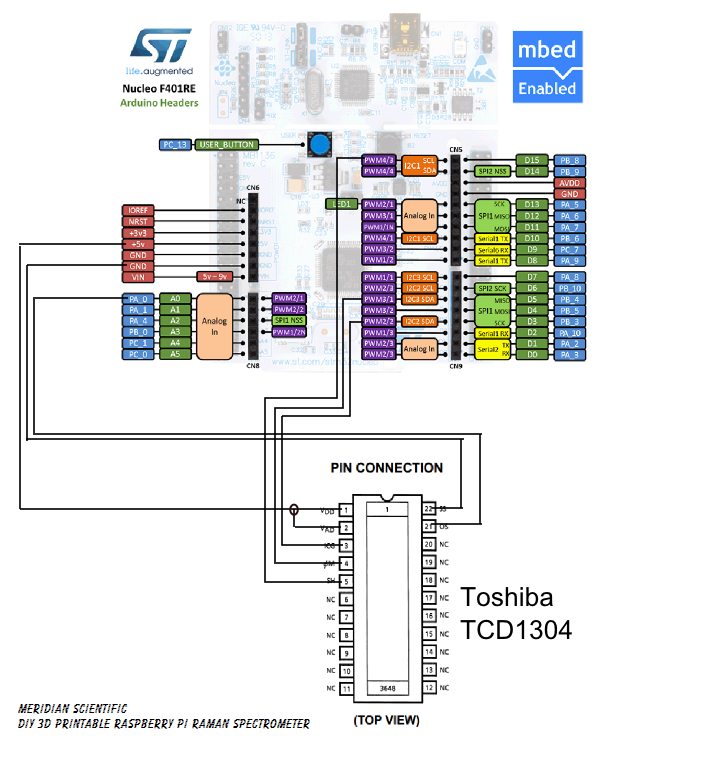
Double check and make sure all the pins are going where they should be......
![]()
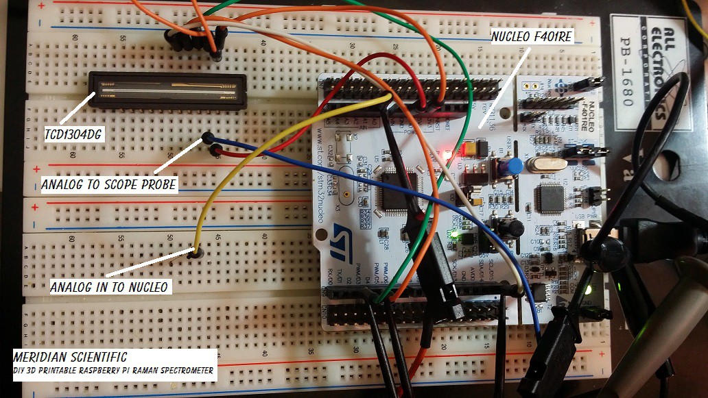
And you have to excuse me.. I've been writing these logs after like 12 hours of working on this every day and I'm usually falling asleep when I'm writing... But here we go... This diagram shows how I have it hooked up for now...
![]()
The Nucleo has a 12bit ADC... I figured that is good enough for my initial testing... As far as how fast it is.... I have to double check that, but I'm not entirely sure it's that critical since I won't be pulling at any high frame rates...
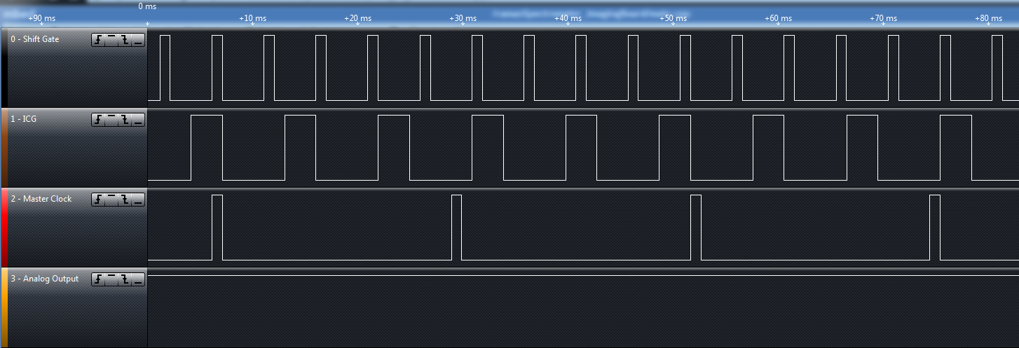
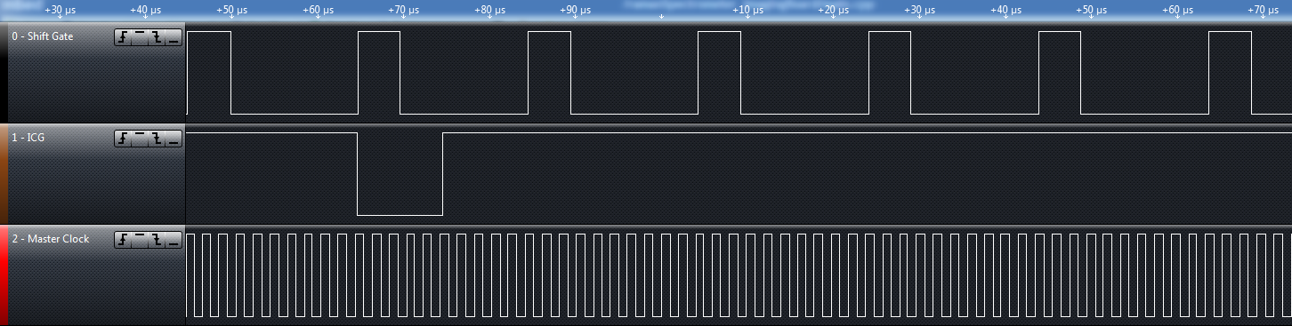
And so.. after MUCH time of going around in circles with the timing... trying to get it just right... testing, changing, trying it again... I hit the money...
![]()
With this, suddenly the scope signal that was kinda working and kinda responsive to light but totally like an old tv out of sync.... Straightened right up and looked like what you would expect.....
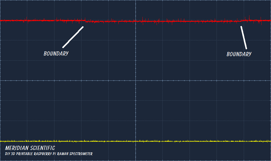
This is a scope capture from the CCD with my hand covering it to make it dark... (It's the red line)
![]()
This is a scope capture from the CCD sitting in the room with just ambient light hitting it...
![]()
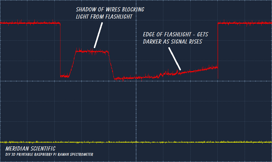
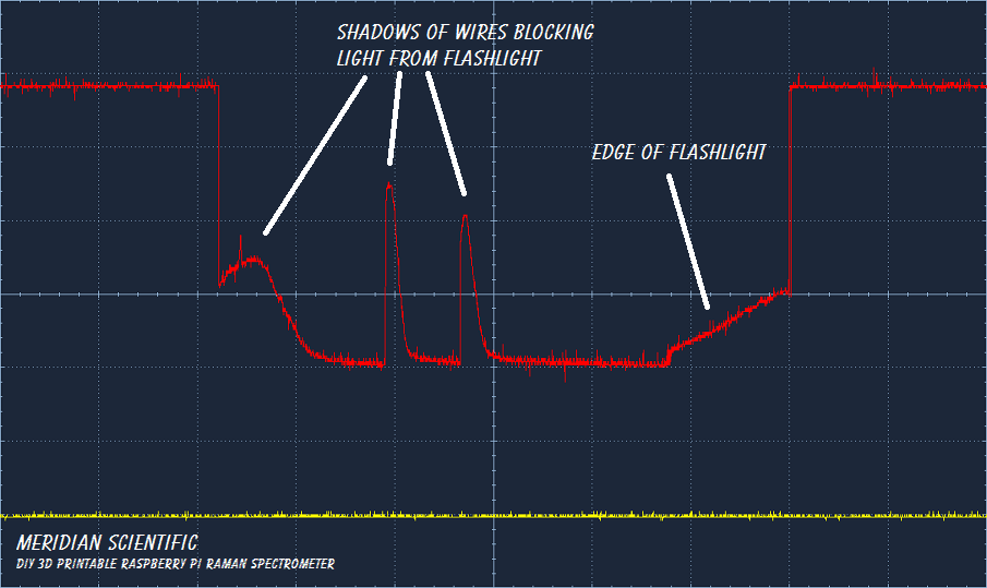
Here, I shined a flashlight and the shadow of some of the hookup wires blocked an area of the CCD....
![]()
Another angle with the flashlight and more than one wire blocking the light...
![]()
So... I have a video of the whole thing working to... I am waiting for it to upload and process... then I will update this post with that as soon as I get up tomorrow... =D
Next step.....Add a better ADC, do some more testing... See if I can clean up the signal... although I am surprised how clean this came out considering it's on a breadboard with hookup wire...
Anyway... Let me know what you think! I'd love to hear it!
![]()
-
Digging deep into designing the spectrometer...
08/08/2014 at 12:02 • 0 comments![]()
So.. When I first started this project.. I had some ideas on how I was going to accomplish this. I was thinking of using the raspberryPi Camera Module, and a diffraction grating I bought on eBay..along with the two edge filters, etc.. I had a lot of parts designed that were sort of an optical table style..with sliding lens holders for the edge filters.. All in open air for the most part..
Lessons learned..
- I probably bought the wrong diffraction grating for what I was thinking of doing.. I did some more research and decided I was going to go with the crossed Czerny-Turner setup.. I am still thinking that is the best option for this device..
- The raspberryPi Camera Module has a number of issues stacked against it. Noise, bayer filter, sensitivity, etc.. This system would probably benefit more from a Linear CCD Array.. That doesn't mean the raspberryPi Camera Module is completely out, I may still design a lower cost option for that...using a monochromator diffraction grating (the original grating I bought actually) and rotate the grating, etc.. We'll see where that goes..
- The original design I had almost completed when I entered thehackadayPrize has been retired in favor of the new tubular design which eliminates a lot of issues...structural rigidity, vibration, stray light, mounting, and so on..plus the new design looks a lot cooler.
So, it's come time to put my brain to work and get the imaging side of this done.. I've started a research campaign to compliment all the great help people here have given me.. (I appreciate it!)..
This document is giving me a lot of useful information.. I've never worked with spectrometers, let alone raman systems before I started this project a couple months ago...and my knowledge in that area is lacking..but I'm trying to make up for it..
![]()
Starting here, I began my planning..
I need to begin by determining the entrance slit size...From B&W Teks website, they have this blurb about the entrance slit...
The function of the entrance slit is to define a clear-cut object for the optical bench. The size (width (Ws) and height (Hs)) of the entrance slit is one of the main factors that affect the throughput of the spectrograph. The image width of the entrance slit is a key factor in determining the spectral resolution of the spectrometer when it is greater than the pixel width of the detector array. Both the throughput and resolution of the system should be balanced by selecting a proper entrance slit width.
The image width of the entrance slit (Wi) can be estimated as:
Wi = (M2×Ws2+Wo2)1/2
Where M is the magnification of the optical bench set by the ratio of the focal length of the focusing mirror (lens) to the collimating mirror (lens), Ws is the width of the entrance slit, and Wo is the image broadening caused by the optical bench. For a CZ optical bench, Wo is on the order of a few tens of microns. So reducing the width of the entrance slit below this value won’t help much on improving the resolution of the system. The axial transmissive optical bench provides much smaller Wo. Thus it can achieve a much higher spectral resolution. Another limit on spectral resolution is set by the pixel width (Wp) of the array detector. Reducing Wi below Wp won’t help to increase resolution of the spectrometer.
Under the condition that the resolution requirement is satisfied, the slit width should be as wide as possible to improve the throughput of the spectrograph.
So... They also state above this that...
The most common slits used in spectrometers are 10, 25, 50, 100, 200 μm, etc.
And.....200um is .2mm ... Which I think is on the sketchy boundary of at least my 3D printer.... So that puts to rest any notion of printing the slit. Which I had tried previously with some sad results.. They weren't terrible, but they weren't great.
So, I will start with a 25um slit.. I plan to acheive this using the 2 razor blade approach.. I would like later on to make them adjustable using tiny stepper motors..I found a bunch on ebay that should work fine for this...
![]()
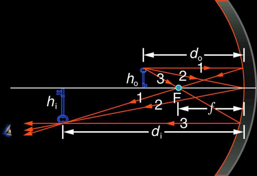
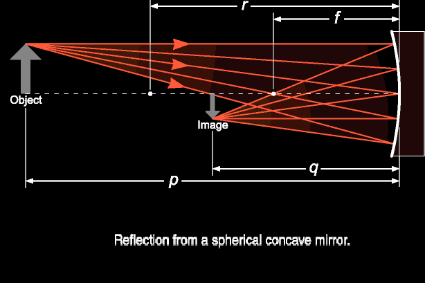
Next would be the collimating mirror.. I am currently working on calculating the focal lengths and angles required.. Not an terrifically easy task.. Ultimately, I believe at this point... since my first mirror's focal length is 80mm, that's the distance the mirror goes from the slit..
![]()
![]()
The above images are used to calculate angles.. My collimating mirror looks like it will be at about a -15deg angle from the entrance slit.. This website explains it pretty well...
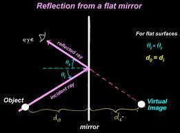
I am using a flat holographic diffraction grating for this attempt.. So, the rules are fairly simple..
![]()
The next mirror is the same concave mirror so the rules above apply there too.. This mirror will be at a -128deg angle from the grating surface.. This will probably change when I look at this tomorrow with a fresh brain...
![]()
On a side note.. I just placed an order for these optics... I bought a couple combinations of mirrors with different focal lengths to experiment with.. These do not have to go into the final design, and suitable eBay replacements probably can be found much cheaper.. But I am gearing this up to be done before the August 20th deadline!
ProductPriceQtyTotal
- 1200 Grooves/mm, 25mm Square, VIS Holographic Grating
- Stock No. #43-216 $135.00
- 25mm Dia. x 50mm FL Protected Aluminum, Concave Mirror
- Stock No. #43-466 $37.50
- 20mm Dia x 80mm Focal Length, Spherical Mirror
- Stock No. #46-239 $37.50
- 50mm Dia. x 100mm FL Protected Aluminum, Concave Mirror
- Stock No. #43-471 $42.50
- 25mm Dia. x 50mm FL Uncoated, Double-Convex Lens
- Stock No. #32-624 $28.50
![]()
-
interfaceBoard adventure update
08/07/2014 at 10:52 • 0 comments![]()
![]()
So, after yesterdays tragedy... I started a new day and decided to just try replacing the questionable cap that I repurposed from another board.. Magic.. Everything worked like nothing ever happened. So.. I'm going to re-examine my choice of parts, etc..
At any rate.. Since it was working again, I had the opportunity to spend some time working on other parts.. And so......
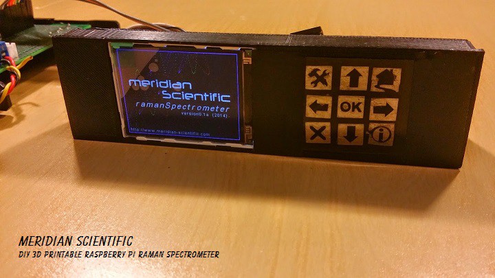
The buttons.. I'm putting together a little how-to here.. I haven't seen this done before.. and I wasn't sure it'd work when it came to mind..and I've kinda had it in the back of my mind the whole time with this project..I designed the 3d printable parts like I already knew it'd work...and it does...like a champ.
So, here's what it looks like..
![]()
![]()
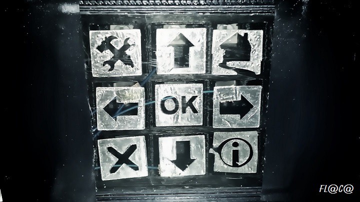
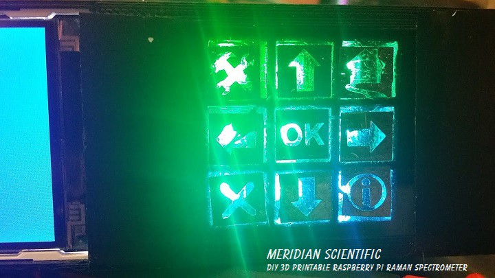
And.. the buttons backlit by the neoPixel RGB LEDs... They are really hard to photograph...!
![]()
This is a really quickly thrown together test example.. I made this panel from the lens out of an imax 3d pair of glasses....(I couldn't find any dark plastic laying around so I will have to buy some...) But it works..
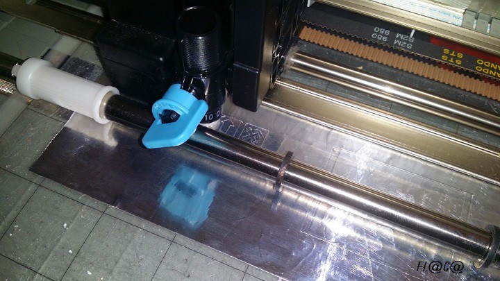
So.. to make a touch sensitive panel like this...
You're going to need something like a silhoutte Cameo or other hobby vinyl/craft cutter.. I use mine for A LOT of things.. If you don't have one.....and can't buy or borrow one... I'll upload a printable template for the keypad that you can trace and cut by hand...or I am also looking into actually etching the keypad on a single sided PCB and letting the light shine through that.. More to come there, but for now.....
![]()
This guide is going to be updated probably fairly soon.. I just wanted to get this up and show how it works and the progress I made..
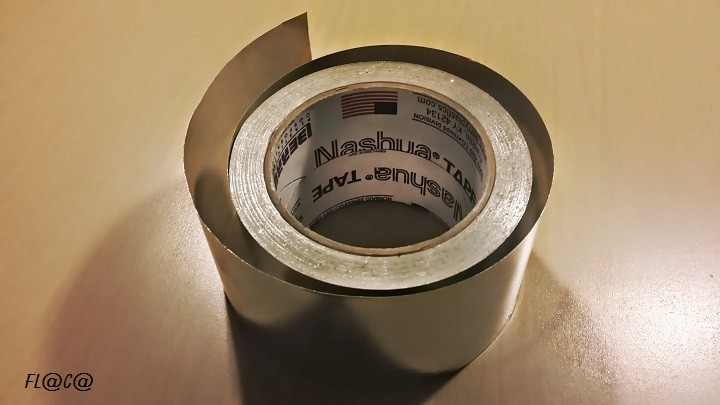
1. Get yourself some aluminum tape... They sell it at Home Depot, Lowes, or other hardware stores... Here it is on staples.com... It's best to get the 3" stuff... If you don't already have this, you should :)
![]()
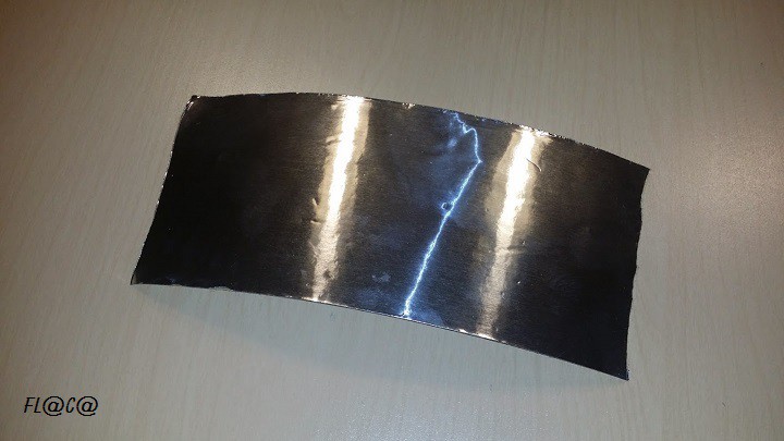
2. Cut a section of the tape about 7 inches or 18cm long..
![]()
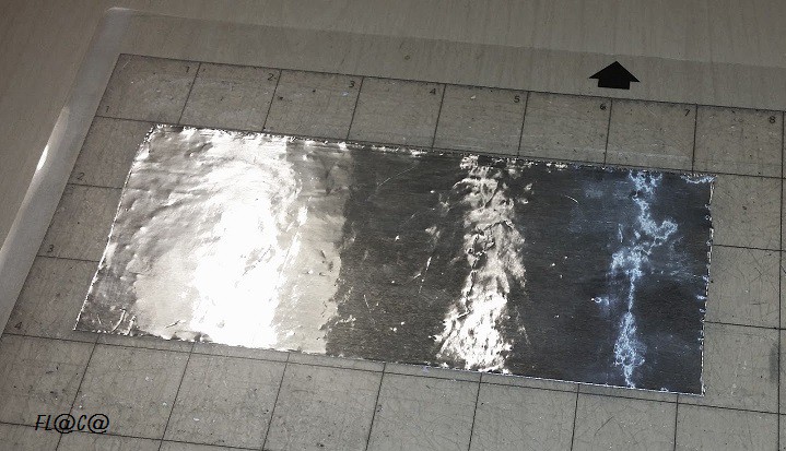
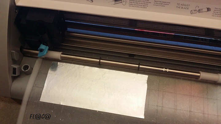
3. Place the cut section on the Cameo's cutting matt...in the upper left hand corner aligned with the file..about 1 inch down and .75 inches over..
![]()
4. Press the cut section and make sure it's adhered to the matt well and is smooth..
![]()
5. Place the mat with the cut section into the Cameo (or other hobby cutter)...and load it...
![]()
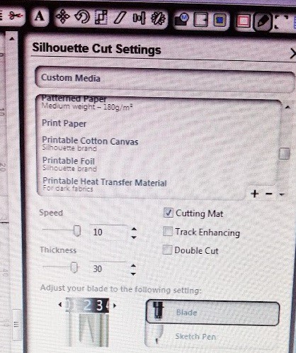
6. With the file loaded in the Cameo software... choose these settings...
- Speed:10
- Thickness:30
- Set the blade at 2
- Use Printer Paper and make sure cutting mat is checked.
![]()
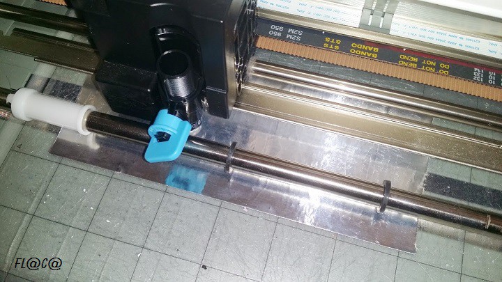
7. Start the cut... and make sure it doesn't bind up in case you didn't flatten it out properly..
![]()
8. The cameo will do its business...
![]()
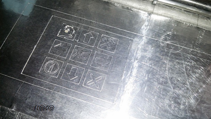
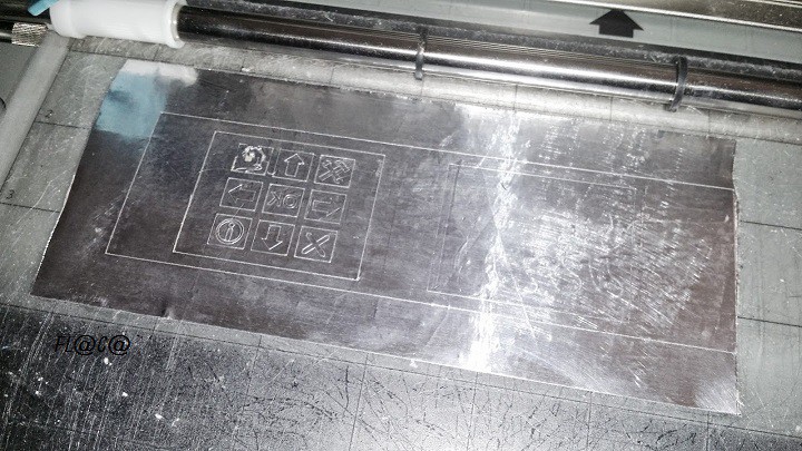
9. When it has finished... You'll have the start of the panel buttons!
![]()
![]()
10. Next you will need to remove the inside of the button icons... and place them on the plastic... Make sure to align them better than I did here...and press them on so they are smooth..
![]()
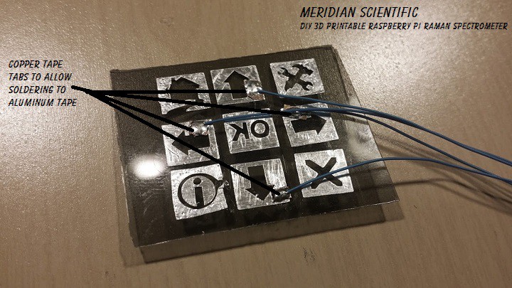
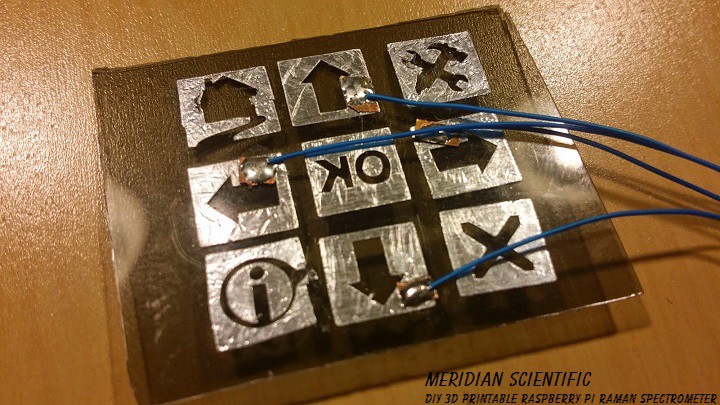
11. When you've got them on.. take a tiny section of copper tape and stick it on the corner of each button and press it on firmly so you have a solder pad to which you can solder the electrode wire...
![]()
12. Solder your wires to each button (I only have four in these pictures...)
![]()
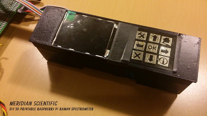
13. Place the button panel in the faceplate... (So, again.. this is my test panel... and it's stuck on with electrical tape for the moment.. I need to find some suitable plastic to use to cover the whole face.. but this worked for a nice test.)
![]()
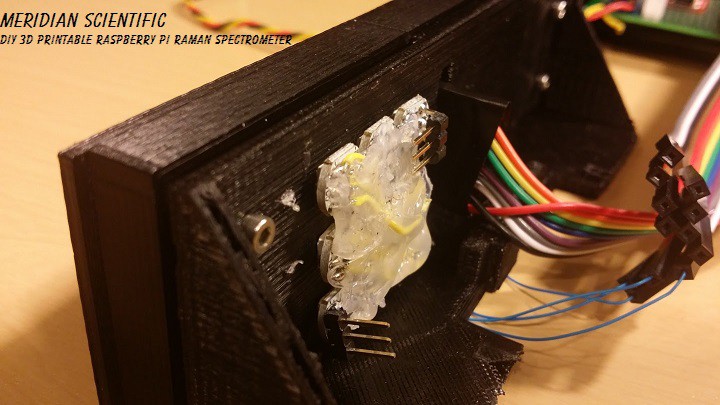
14. Wire up the neoPixel RGB LEDs...
![]()
15. Power it all up!
![]()
And it works!
![]()
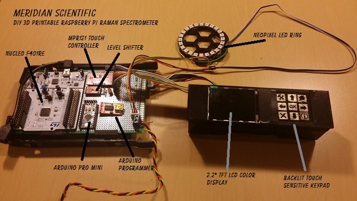
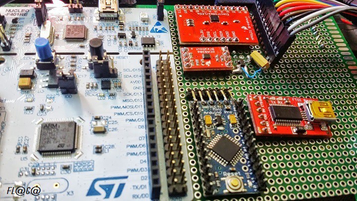
So, here's the board with the display panel and neoPixel ring...
![]()
And a closeup of the board.... The sparkfun MPR121 and level shifter are going to be ripped off the board and replaced with a new adafruit breakout that has the 3.3v regulator and the level shifter all in one breakout... That should be here Friday..
And since I'm not able to go to Defcon, I'll be working on that instead.. :(
![]()
It still needs a little work.. But this is a great proof of concept...!
![]()
-
interfaceBoard update
08/05/2014 at 11:11 • 0 comments![]()
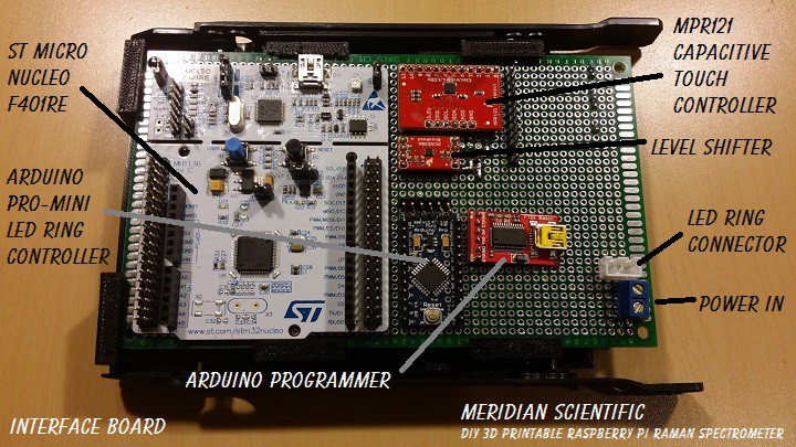
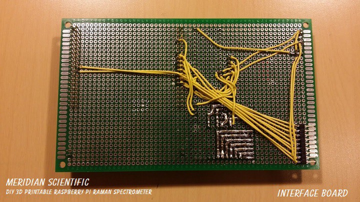
So the level shifter for the capacitive touch controller (MPR121) came today...
The interfaceBoard now has the touch controller, the nucleo, and arduino pro-mini (for the LED ring) and it's programmer.... I've got everything wired up and ready to test....which will happen tomorrow..
Here's a couple shots of the board as it stands..
![]()
![]()
This is of course the prototype..and I'll be creating the eagle schematics and board layouts from it as soon as it's all tested... The connector on the bottom right in the second picture is for the TFT display...
![]()
Update to this update... First failure..
I started my testing this afternoon... Had a little trouble getting it to work at first... Broke out the logic analyzer... turns out the sparkfun board for the MPR121 comes with the pullups active...and so does the level shifter breakout.. oops.. Tried again.. nope. Long story short, I fumbled around... turned out to be the code..after I weeded out all the hardware glitches... The code example on this page worked perfectly.. So... awesome! I got the touch panel controller working, then I added that code to my test program for the TFT... made some mods and got it displaying a different screen for each button I press... Cool!...the road to progress... so then I started whipping up a little test keypad with some electrodes... and I look over and see a little puff of smoke and a TON of 'failure to communicate to i2c' errors zipping on the terminal screen... AGH...!! I pull the power connectors, etc... the puff seemed to come from the failed capacitor on the 3.3v regulator (MIC5205-3.3BM5 (LB33)).. Not cool.. So...... Not entirely sure why it failed...except I had to salvage it from another board since I didn't have any laying around.. Looks like another order is in order.. Hopefully it didn't fry the MPR121 or the level shifter, etc.. I would be sad.. But I am going to order spares along with the cap to be sure... can't afford to wait!
I've got a mouser order on its way for some additional parts to build up the CCD detector.. So looks like until then it's more work on the filter selector, etc..!
![]()
-
The filterWheelAssembly...
08/04/2014 at 12:15 • 0 comments![]()
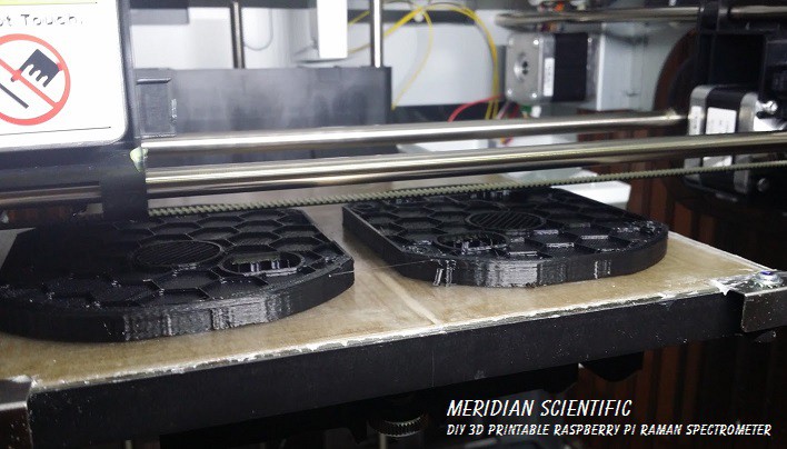
It's coming right along... I have the outer casing and the wheel itself printable now... The stepper motor fits perfectly, and the optical encoder fits too.. The filter wheel has nice mounting holes to make the filters removable, etc..and that way you can customize a mounting bracket to fit whatever optics you need without changing the wheel itself..
Here is the outer casing being printed...
![]()
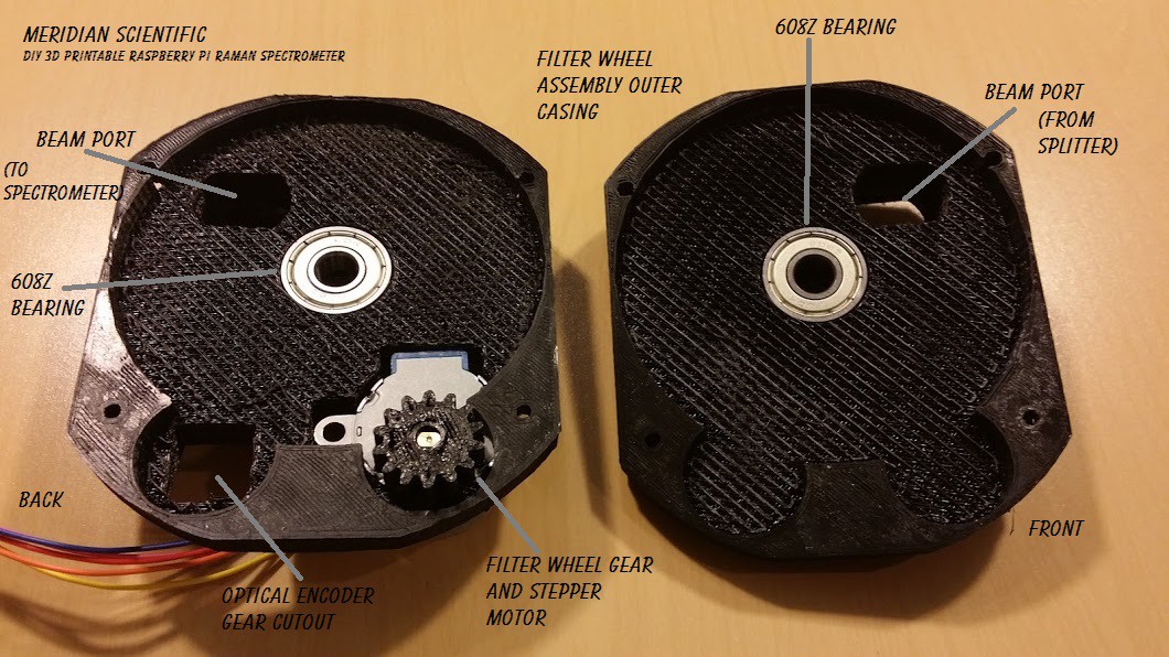
The front and back with the stepper motor in place...
![]()
The inside with the bearings, stepper motor and filter wheel pinion gear...
![]()
A closer inside shot of the back...
![]()
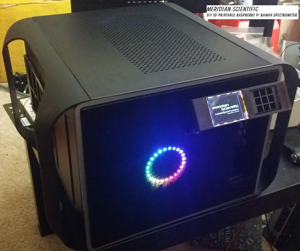
Here are also a couple nice shots of the case and the front panel as promised!
I think it's actually starting to look pretty good...!
![]()
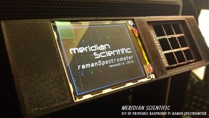
The front panel without the smoked glass cover which has the electrodes for the capactive touch keypad on the right...
![]()
Some laser action..... =D
![]()
![]()
-
Laser Emitter Alignment Test
08/04/2014 at 12:06 • 0 comments![]()
So, I started testing the process to align the laser.. I need to add a couple screw holes in the mirror mount and a place for the spring/grommet I use to hold it.. But I think the test came out pretty successful.. As it was pointed out, it does seem to make sense to put a coating on the inside to limit the stray light and reflections inside the beam tubes.. Here's a quick video showing the laser running in the assembly...
My next step is to get the beam splitter in there, with the adjustment screws in place for the mirror and see if I can get a solid beam out the objective lens and centered through the beam port to the filters... I am sure I'll have to place some adjustment screws on the mount for the beam splitter too....baby steps.. :)
![]()
-
Formulating a plan for the spectrometer portion..
08/01/2014 at 06:48 • 3 comments![]()
I always think ahead a bit... Starting with a rough idea, and gradually refining that until reality starts dictating the direction.. It's a balance I think most hackers battle with.. So, I had some grand ideas at the beginning of this project, and some misunderstandings of certain things, and a whole lot of research and learning has brought me a little closer..but I think that's what this whole thing is about.. It's all about learning and trying to do better. This project has definitely been a learning experience.. in multiple ways...and I continue to learn more and more..
So, having said all of that.. I have been upgrading my research efforts on how exactly I am going to tackle the final design of the spectrometer portion of this system.. There's certainly lots and lots of options.. My goals are to make it cheap, configurable, easy to build, and upgradable..
So.. There's some factors to consider.... What type of imaging device do I use? What type of optics do I use? How do I fit this all in and still make it work?
Well, in respect to which imaging device do I use.... I started out with the notion that I was going to use the raspberryPi camera and take multiple exposures, do some image stacking and so on... The tradeoff would turn out to be more significant than I originally thought.. Turns out factors such as the Bayer filter and noise would be a major limitation. I then turned my eye toward Linear CCD Array Detectors (Linear CCD).. As it turns out there are a couple that are most popular in spectrometers.. The Sony ILX511 and the Toshiba TCD1304AP.. From what I can see, it is relatively simple to interface to these devices.. The Sony from what I can tell is no longer in production (from what I can tell).. The Toshiba seems to be still around.. Both are not terribly easy to source...unless it is through eBay and is accompanied by a few weeks of waiting... At my stage in this project, and with the hackaday prize deadlines... I can't wait until September..
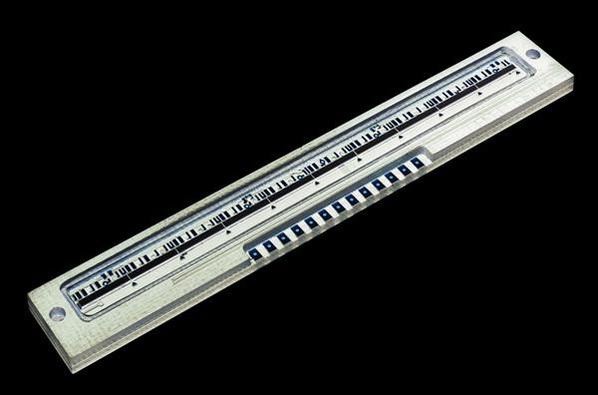
So, in a mad search today.. I discovered the AMS (formerly TAOS) TSL1410R..
![]()
![]()
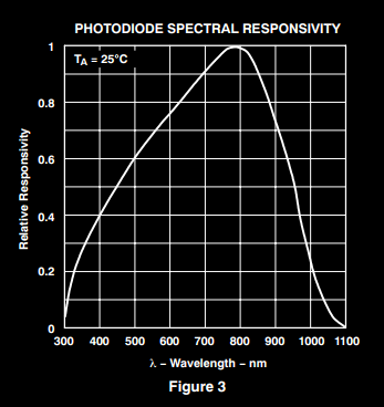
It isn't a CCD device.. Rather it is a diode sensor array.. It consists of two arrays of 640 photodiodes.. It's 400dpi and "The pixels measure 63.5 μm by 55.5 μm with 63.5-μm center-to-center spacing and 8-μm spacing between pixels." The TSL1410R seems to have a decent spectral range... at ~300nm to ~1100nm..
![]()
It looks like it will probably need cooling because the dark output voltage tends to rise when it gets around 40C... Not sure if it'll truly get that high, but I already have the circuitry in place and it's better safe than sorry.. This device also has an eval board available..which will make a handy reference for designing the driving circuitry.. The other option is to just go with something like a used ocean optics device or similar.. I feel that is kind of a cop out and I should not include something like that since it might be hard to source and is probably too expensive.. And then there's the option of just going with the Toshiba device... which I am still not ruling out.
So, the optics.. This is always a tough department because they are usually the expensive and prohibitive part of everything....and they make a difference. What I'm trying to do is make a reasonably easy to build/source and fairly cheap device. And people can pick and choose, and upgrade for their purposes. So, in the effort to establish a starting point... I'm thinking of going with the Crossed Czerny-Turner... Not the cheapest route, that'd probably be something with a transmission grating made from a DVD or some ruled film from eBay..which I've tried... and I'd like a little better results than that..
So, I am looking at the Edmund Optics 25mm Dia. x 50mm FL Protected Aluminum, Concave Mirror Stock No. #43-466 priced at $37.50ea for the collimating mirror and the imaging mirror.
- Diameter (mm): 25mm
- Effective Focal Length EFL (mm): 50
- Radius (mm): 100
- Edge Thickness ET (mm): 3.00
![]()
And the Edmund Optics 1200 Grooves/mm, 25mm Square, VIS Holographic Grating Stock No. #43-216 priced at $135.00 for my grating surface.
- Dimensions (mm): 25x25
- Groove Density (grooves/mm): 1200.00
- Thickness (mm): 9.5
![]()
Where these are not what a lot of people consider 'cheap'... they are as far as this stuff goes.. It's actually cheaper than anything I could find on eBay....used.
![]()
-
Filter Wheel Assembly Design Near Complete
07/30/2014 at 10:01 • 0 comments![]()
So, I have a few details to add and work out... but the first draft is looking good.. I'm going to add a few things (mounting holes for the filter adapters and such), and clean up the code..right now I don't think it'd print too well... I also need to separate all the parts such as the wheel itself, and the body, etc.. into individual files...
Here's a couple shots that show what is going on pretty well..
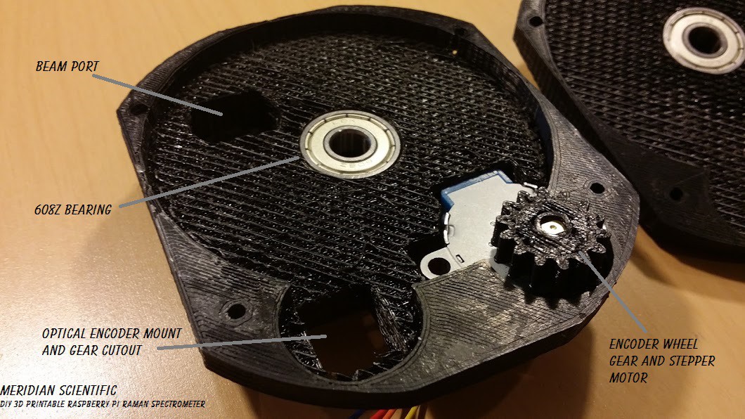
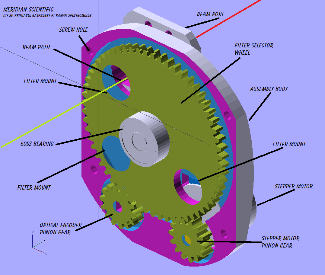
This one shows the inside... the big gear is the filter wheel and the holes are where the filters mount..the whole thing spins around and allows you to select the filter for the exposure your working on..The two gears below are the stepper motor drive pinion(right) and the optical encoder pinion (left), which allows the system to track the filter position..
![]()
The backside...Showing the stepper motor, the exit beam path, the screw holes and the mounting hole for the optical encoder...
![]()
I expect I'll have this done in the next couple of days.. I'll print it up and post it here as soon as I do!
And then I'll be on to laying out the collimating lens / entrance slit and then it's on to the actual spectrometer! That should be fun.. I need to purchase a new diffraction grating and a couple of mirrors soon...
![]()
ramanPi - Raman Spectrometer
The open source 3D Printable Raman Spectrometer using a RaspberryPi and easy to find off the shelf components..