fl@C@
fl@C@-
Considering a new approach
06/09/2014 at 12:45 • 0 comments--
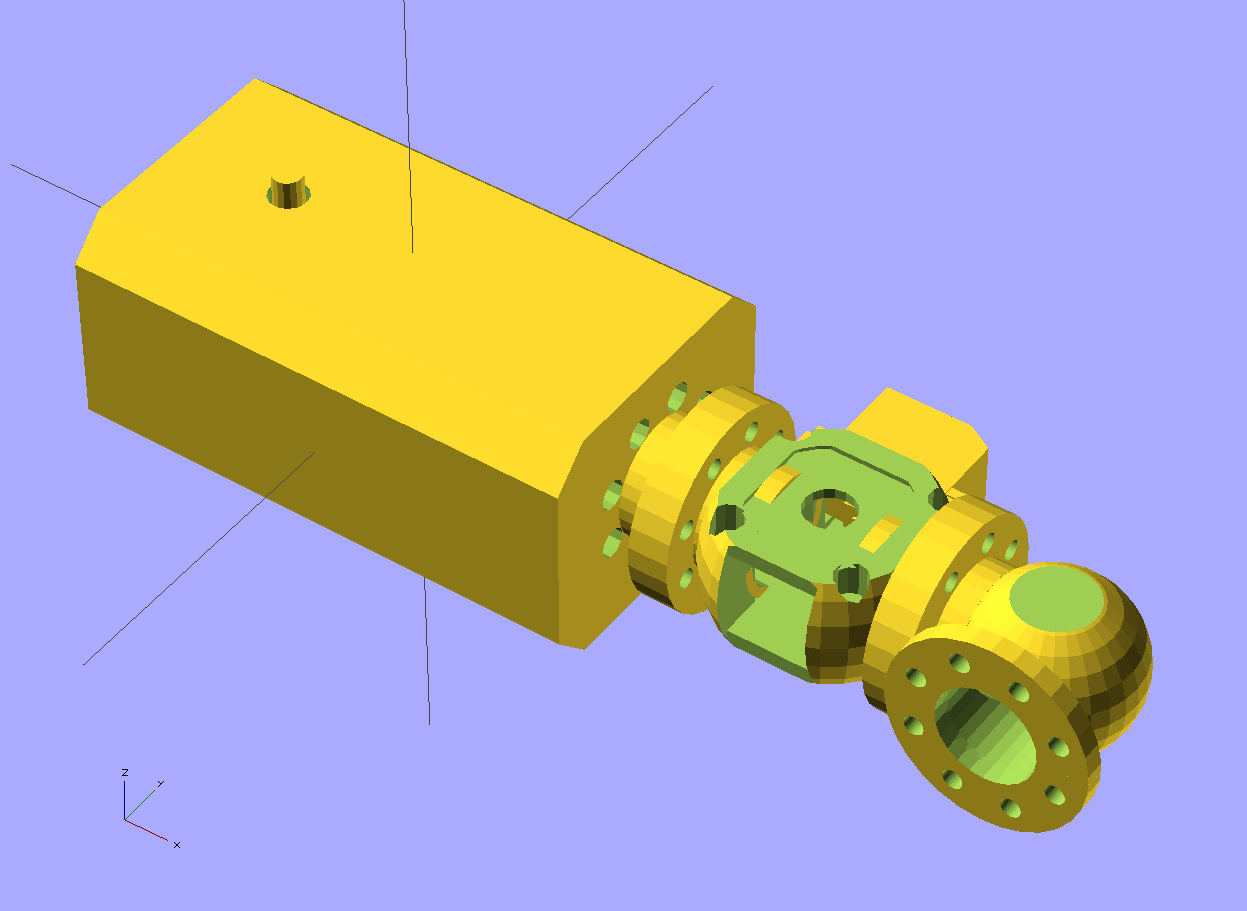
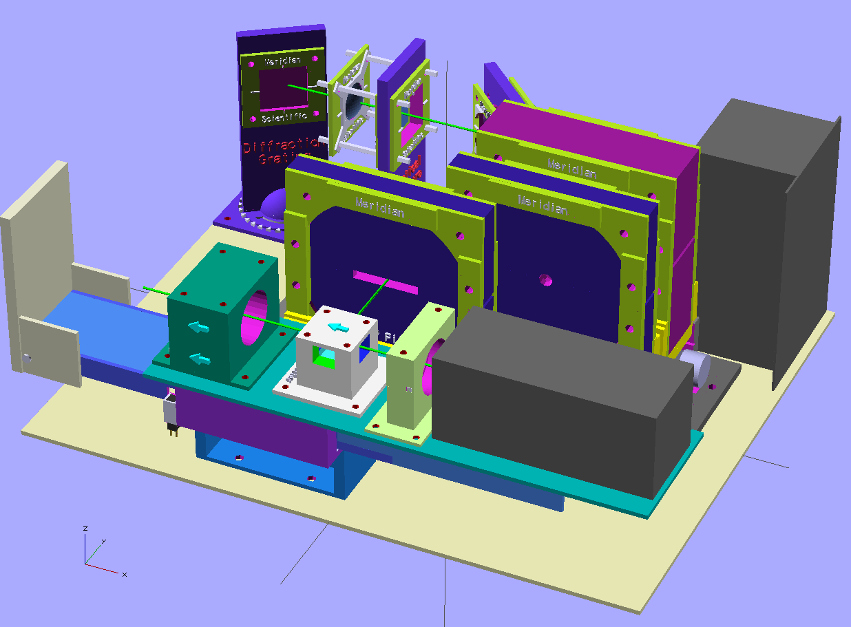
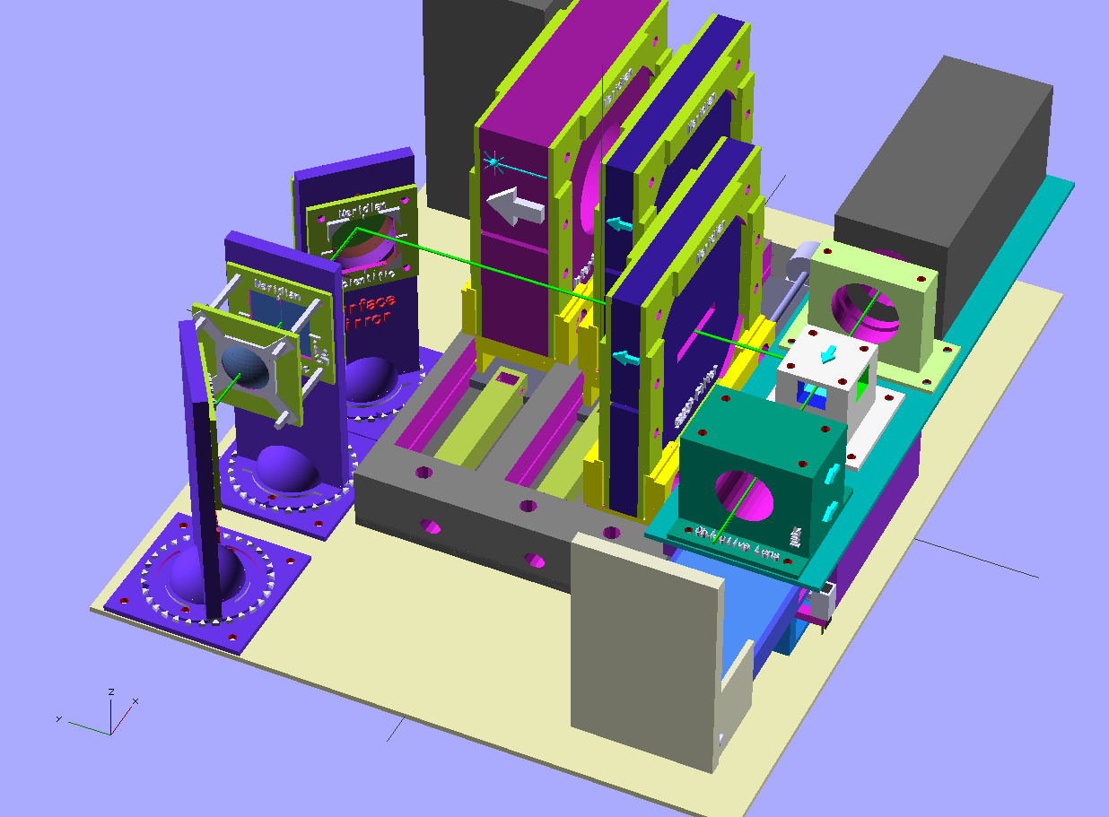
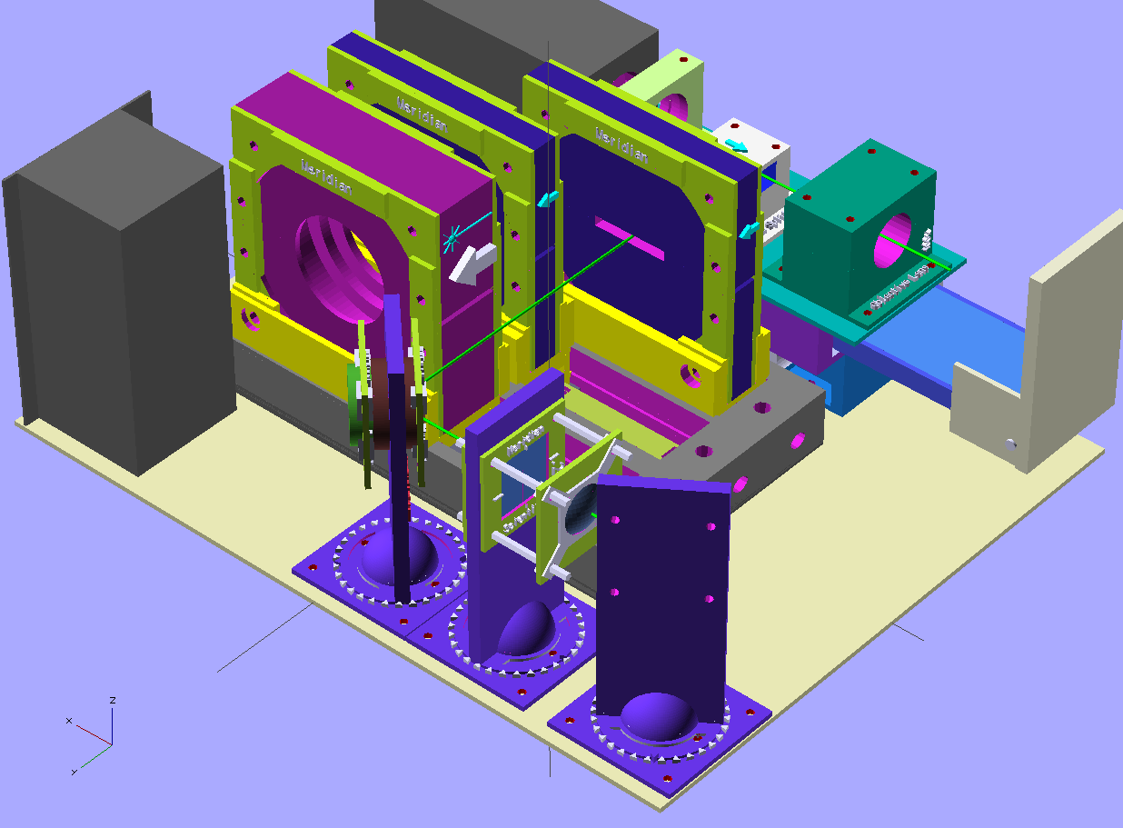
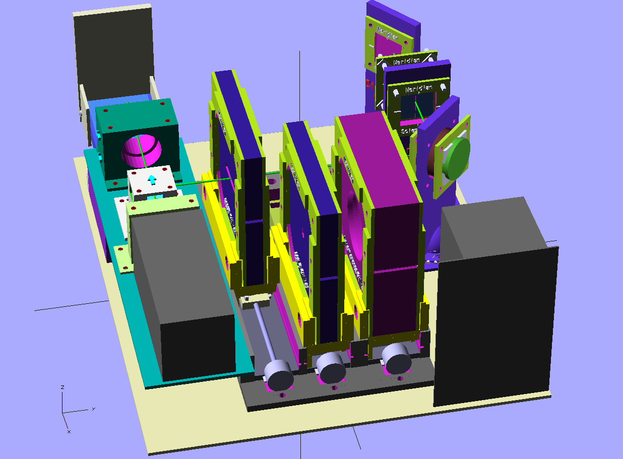
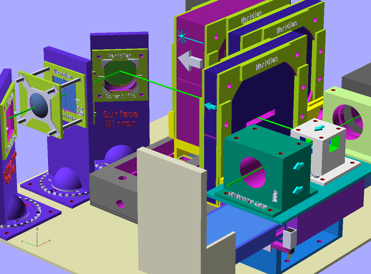
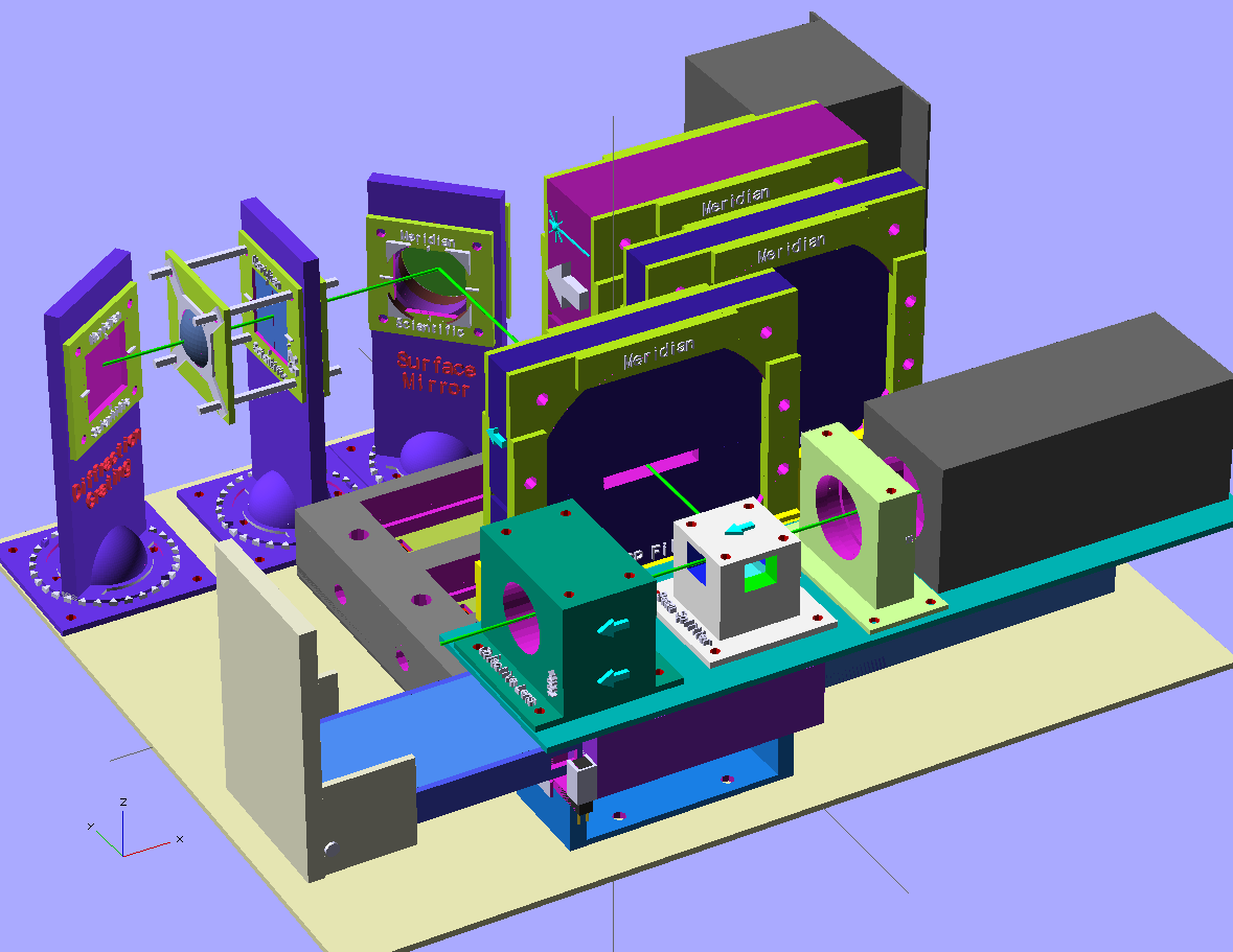
So, in an effort to simplify and make a more robust system... I'm considering this new approach.. Instead of having so many separate objects, all having to be mounted individually, aligned, etc... I'm looking at this more enclosed system.. Basically, the laser is attached to a series of modules...all connected using flanges.. Each module contains a part of the spectrometer... a mirror, a lens, or filter or a mechanism, etc.. Here is what I have conceptually so far..
![]()
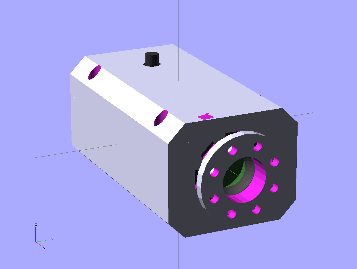
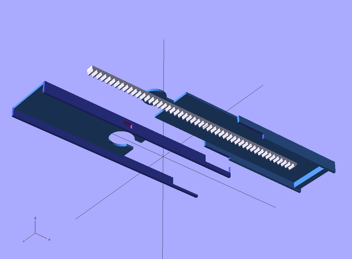
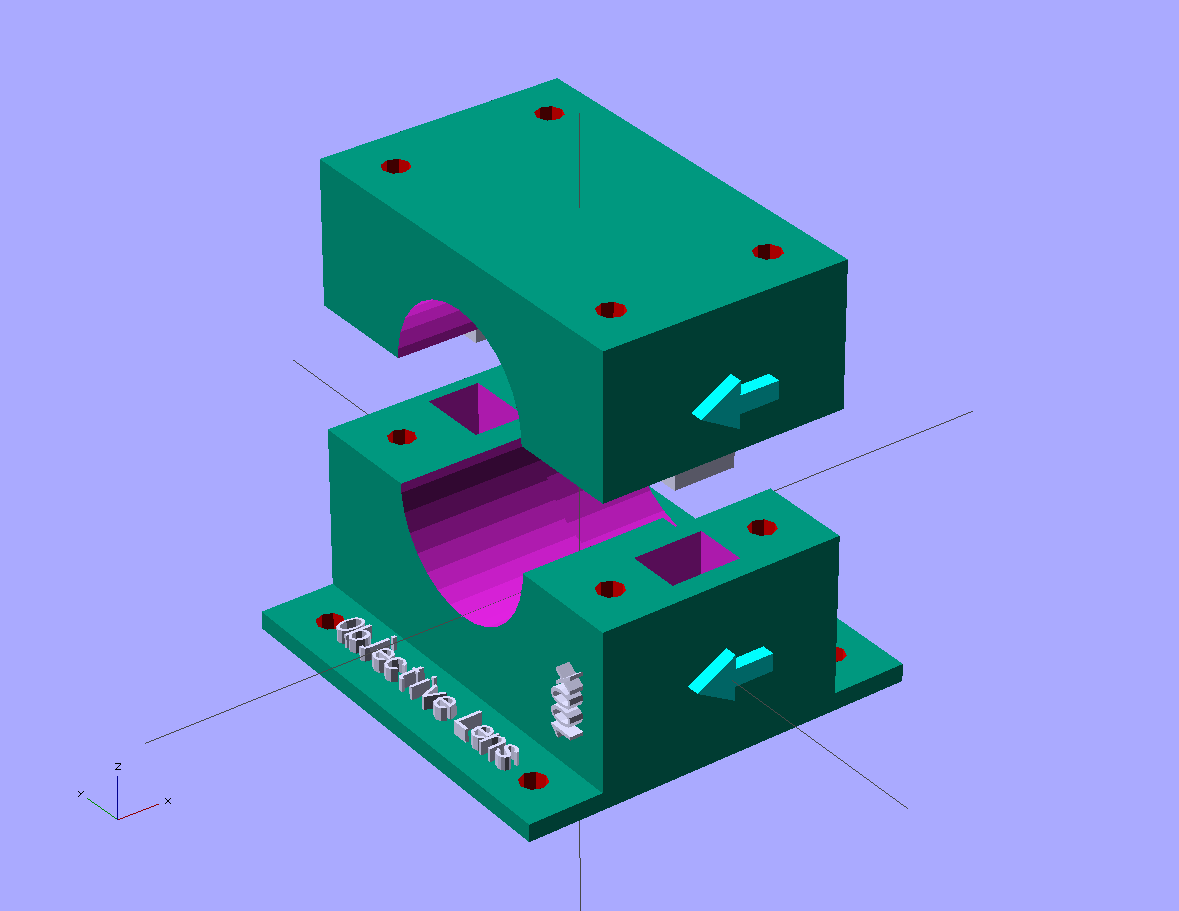
This part contains the laser on the left..connected to a module that holds the 532nm pass filter and a shutter mechanism driven by a servo.. that is then connected to the right angle module that contains a surface mirror. That will in turn connect to a module housing the beam splitter, then goes forward to the objective lens mount and cuvette holder and mechanism.. The beam splitter also would branch off parallel to the laser and connect to a much smaller shortpass/longpass filter mechanism which will probably also contain the vertical aperture as a modular attachment depending on if I make it adjustable or not... that connects to the collimator module and so on... This approach will make a much sturdier system, block out any external light sources, keep dust and dirt out, avoid any stray laser reflections from exiting and hitting your eyes, but still be modular and configurable...and modifiable.. It will probably lend itself to a wider range of cases too.. I'll probably rethink the laser mount, even though there's plenty of airflow and the laser is thermoelectrically cooled, I don't want to risk it..I'll test a couple different ideas with that.
Here's the individual modules you see above... and of course, they're all up on gitHub right now...
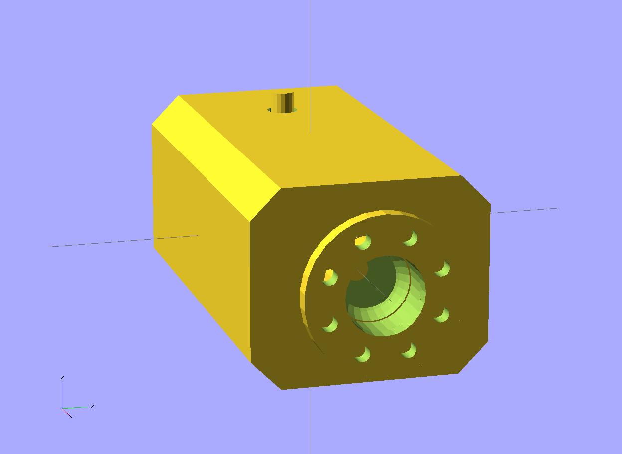
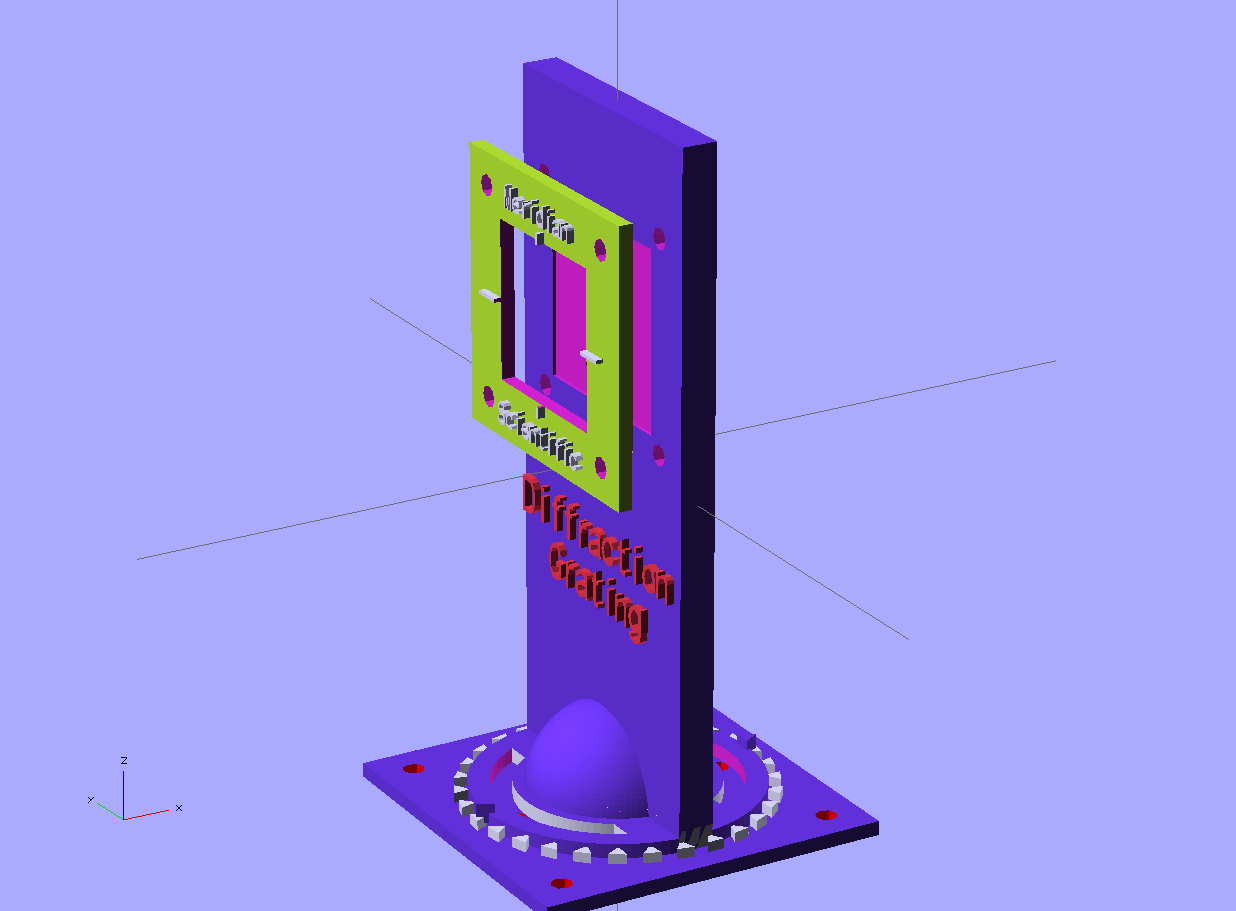
This is the laser emitter..
![]()
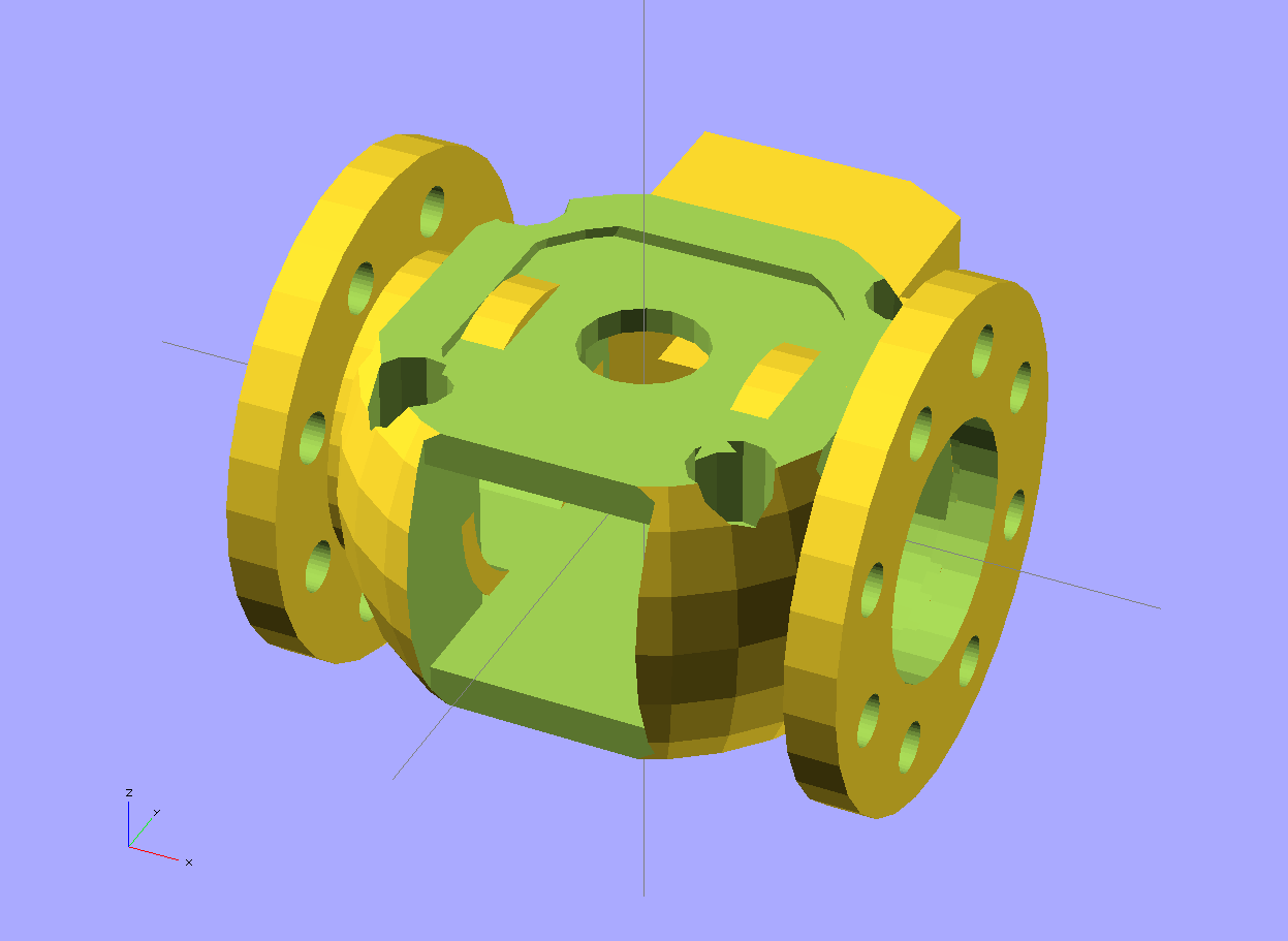
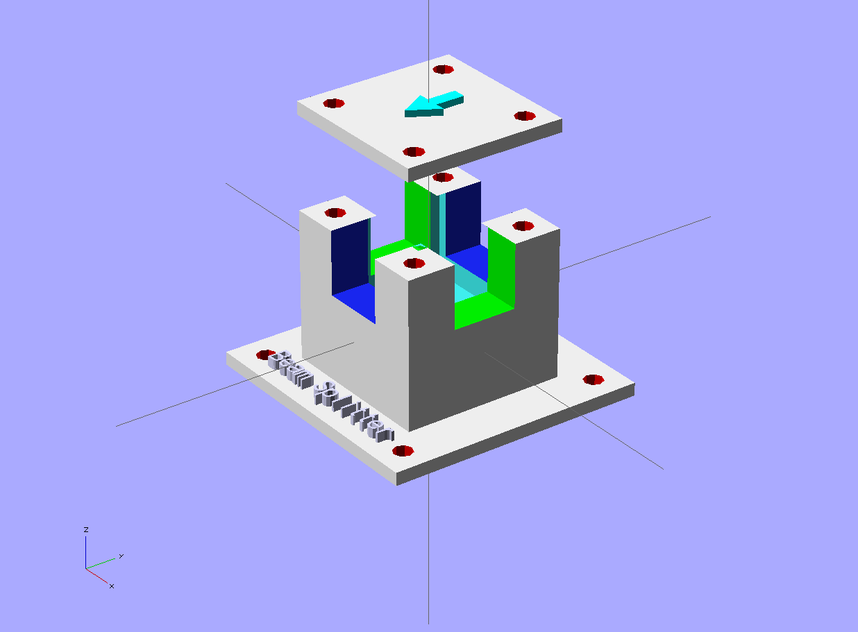
This is the 532nm Pass Filter and Laser Shutter...There's a port on the top so when the paddle blocks the beam it is reflected to a translucent plug in top that is illuminated to indicate the beam is on and blocked...and there's a portal on the side to allow observation and access if need be..
![]()
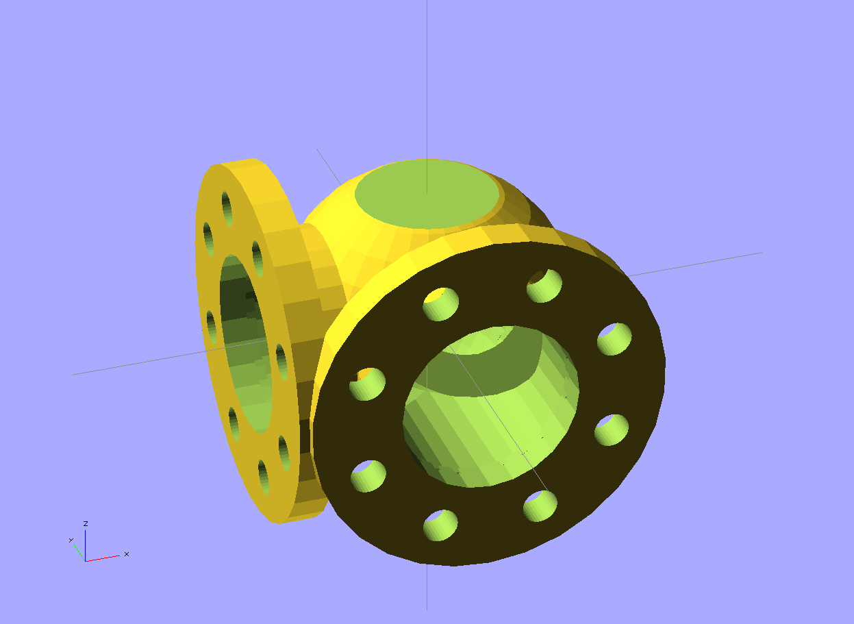
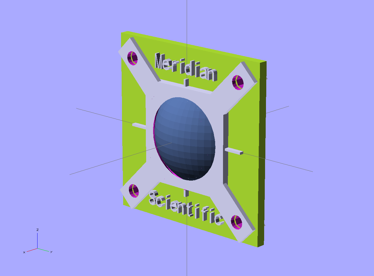
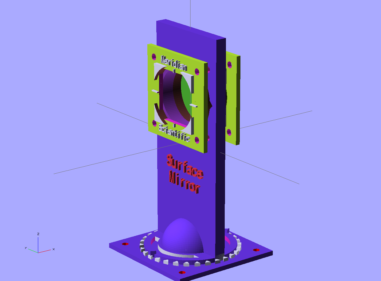
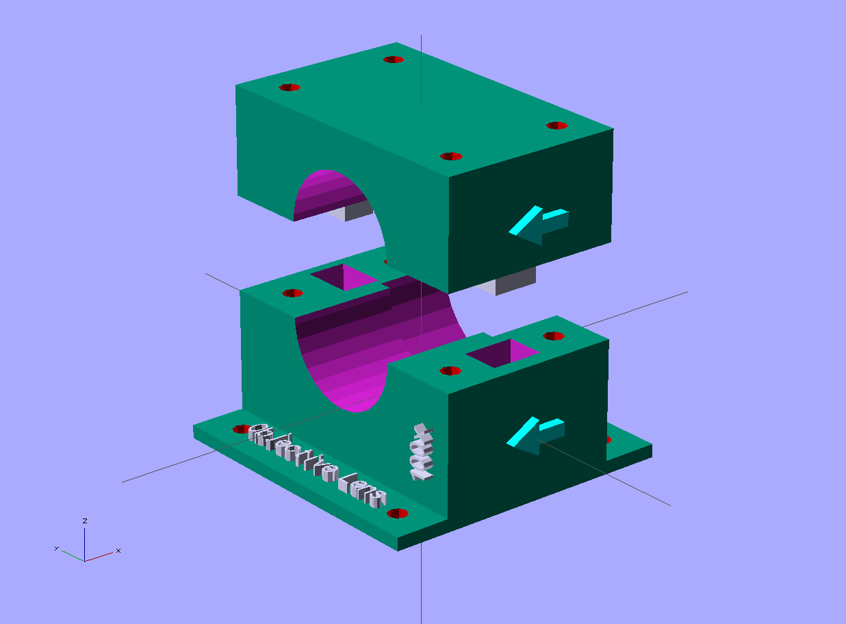
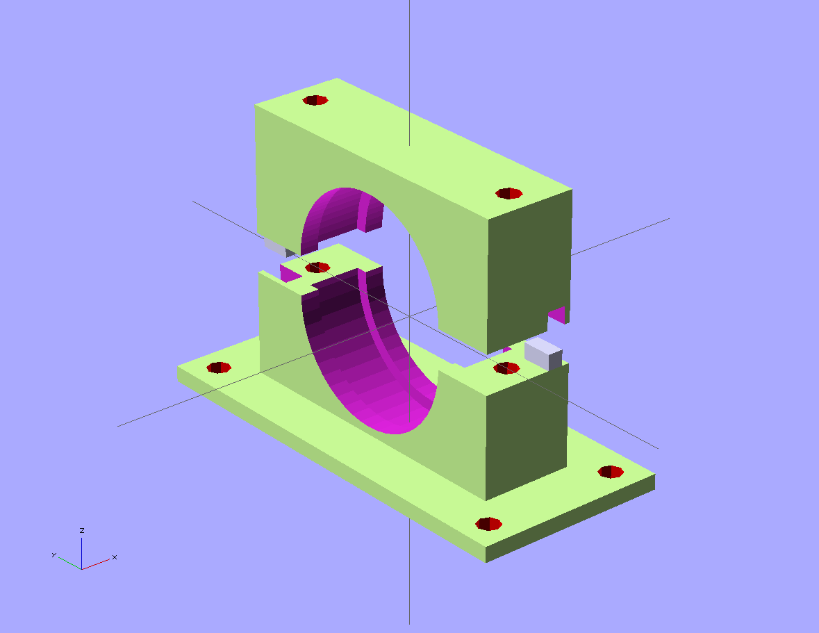
This is the mirror mount..which will soon connect to the beam splitter module...
![]()
If anyone has any thoughts or considerations, I'd love to hear them!!
-
Update
06/09/2014 at 00:09 • 0 commentsI have been working on a change that will be a pretty significant improvement in a couple ways.. Here's a preview... I hope to have more up later today...!
I'm doing a bit of miniaturization with some components, and integrating others... which will ultimately make the whole thing easier to assemble and be more sturdy at the same time..
Thanks to jk, Jason, Thomas Shaddack and medix for all of their input!! More to come soon!
![]()
-
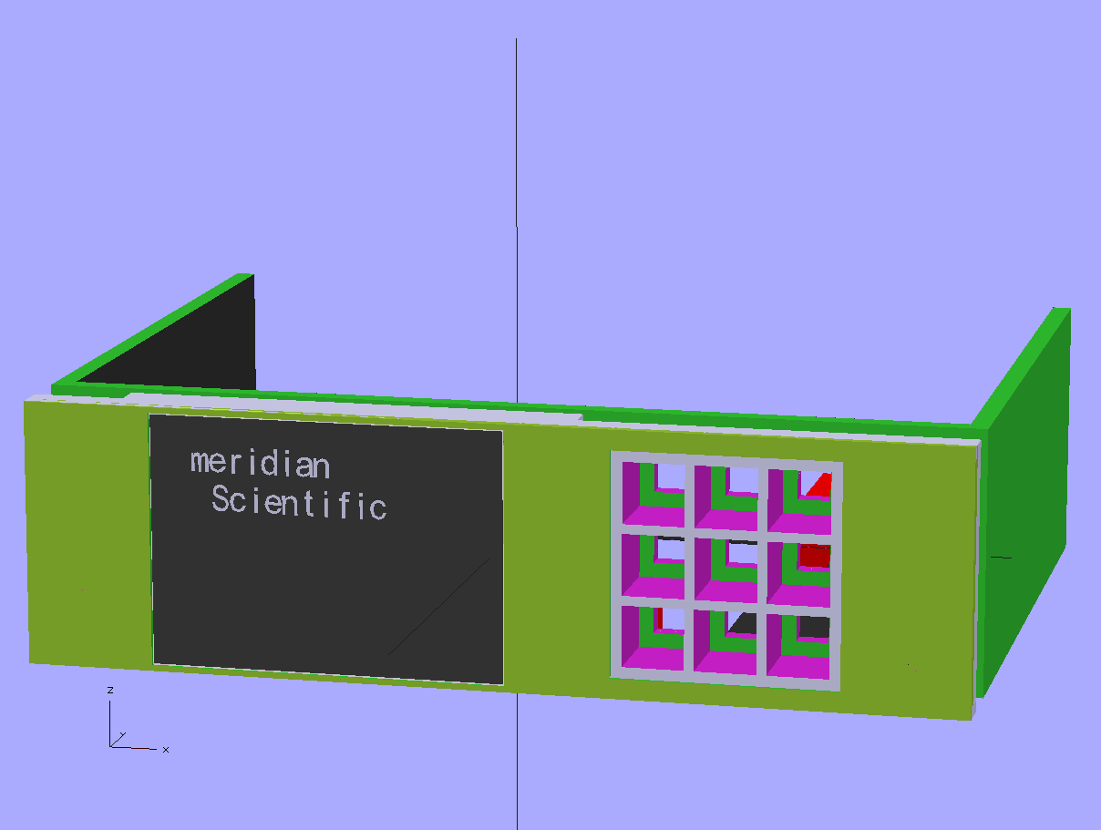
Display, faceplate and control board tray...
06/05/2014 at 11:47 • 0 commentsSo, I got the nice eBay $5.57 TFT 240x320 ILI9341 display working with the nucleo and designed a nice faceplate and tray for the 5.25" drive bay..
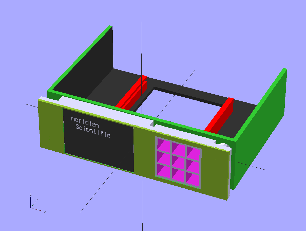
The empty boxes on the right are for the 'keypad'.. A pcb mounts on the inside of the box which has the interface electronics and an led that pokes or shines into the holes... A piece of smoked acrylic covers the entire panel and a vinyl cutter cuts some sticky copper foil (which is cut in reverse and stuck on the inside of the acrylic panel) with the silhouettes of the key graphics so the led shines through and is visible when illuminated through the acrylic....the copper is connected to a capacitive touch circuit and registers when that 'key' is touched.... Right now, this is all theoretical...but I'm hoping I can pull it off.. It shouldlook pretty cool. I might try glass instead of acrylic depending on the results...
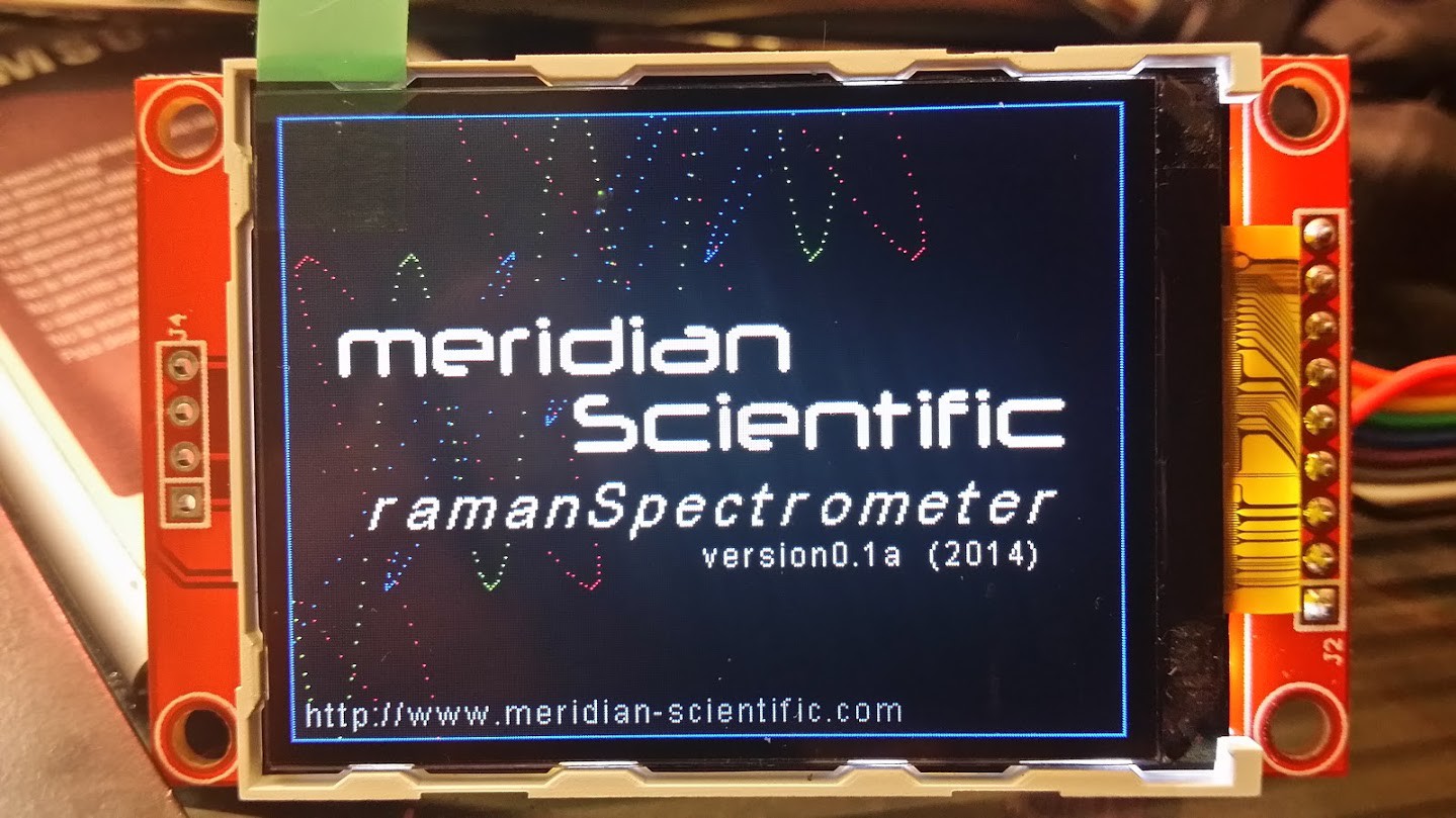
The display itself…works great..!
![]()
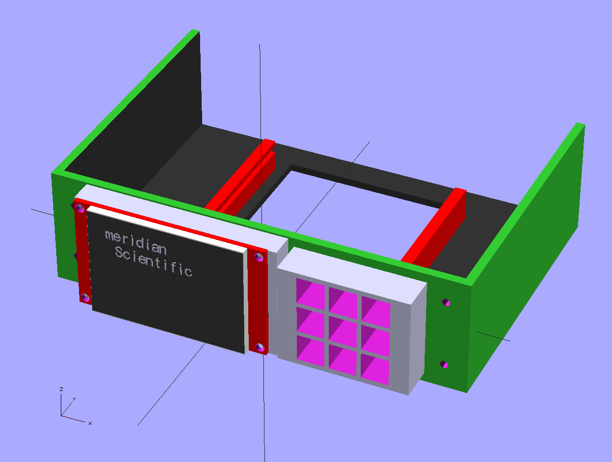
Here's the entire assembly minus the nucleo board...
![]()
From the back with no nucleo..
![]()
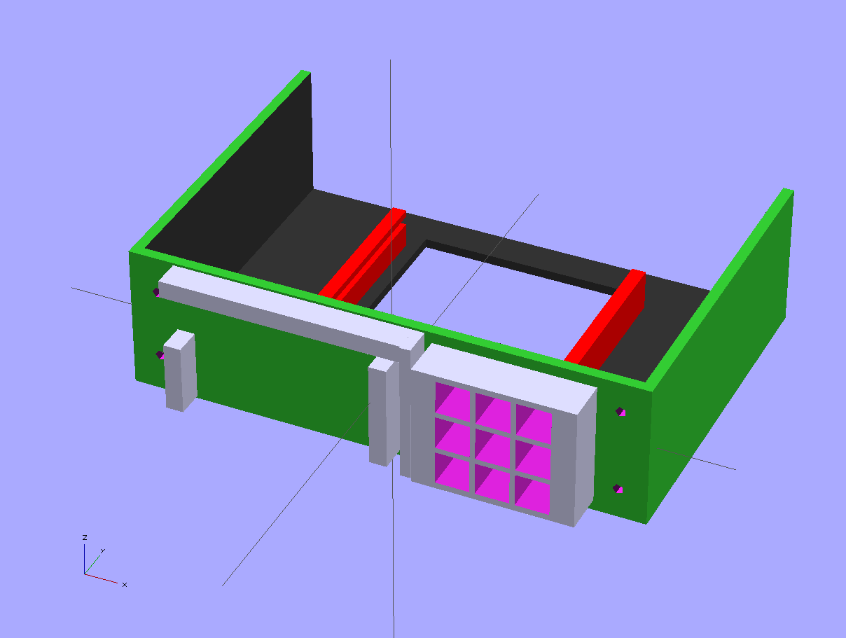
The front...![]()
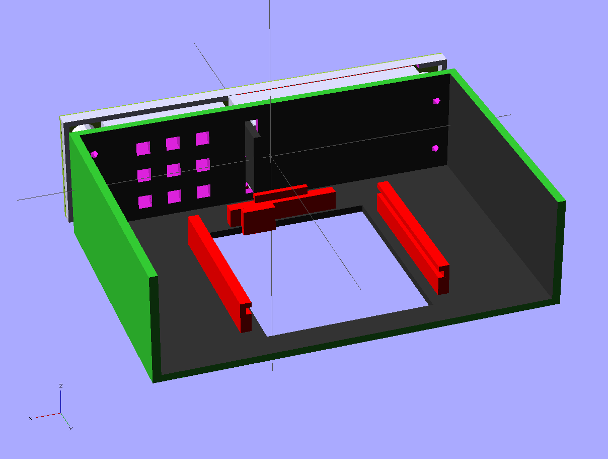
No faceplate, from the front...
![]()
No faceplate or TFT...front..
![]()
-
Some pictures..
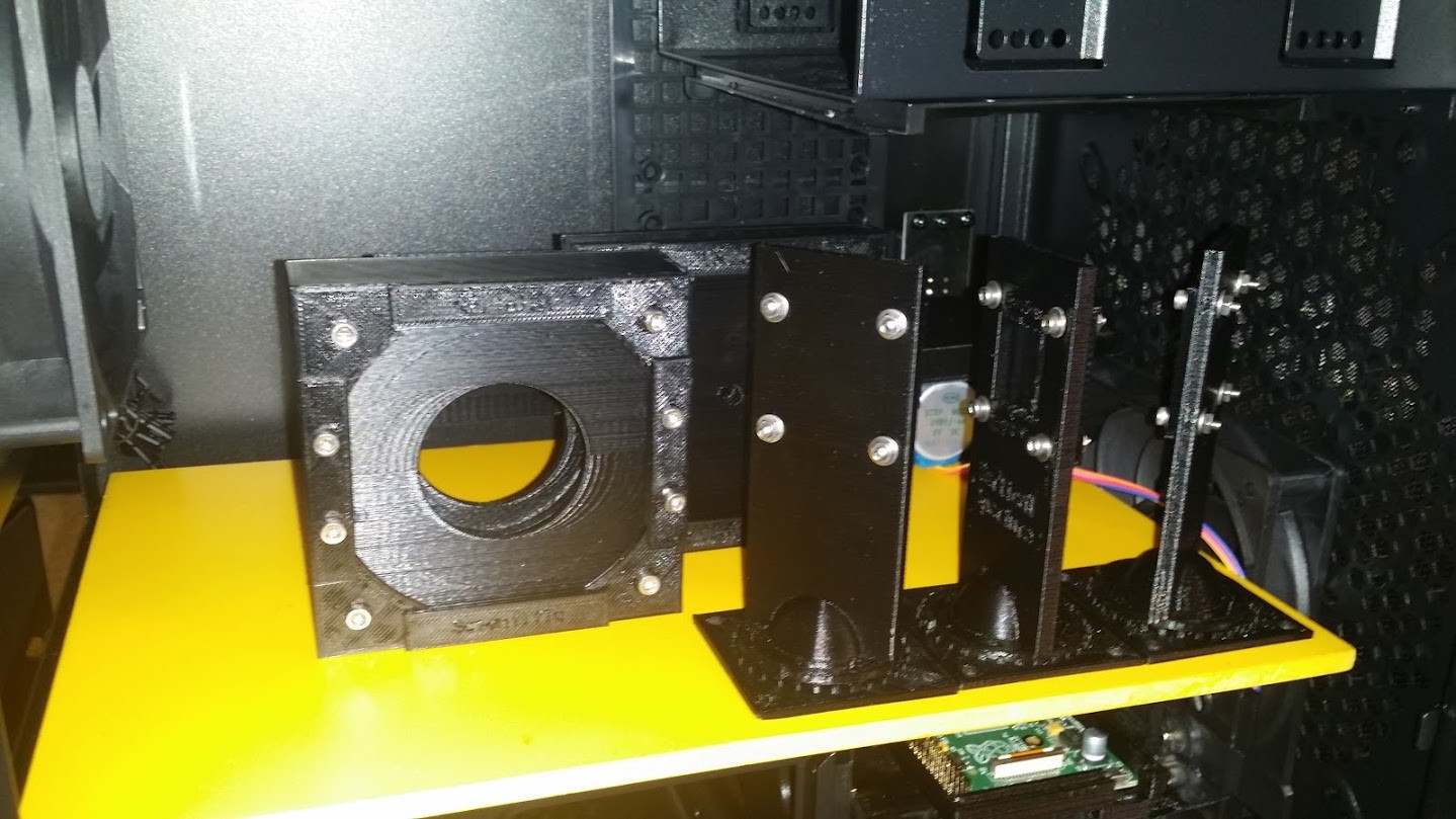
06/03/2014 at 13:10 • 1 commentHere's some pictures of some objects printed out...
Trying out the fit inside the case...early on..
![]()
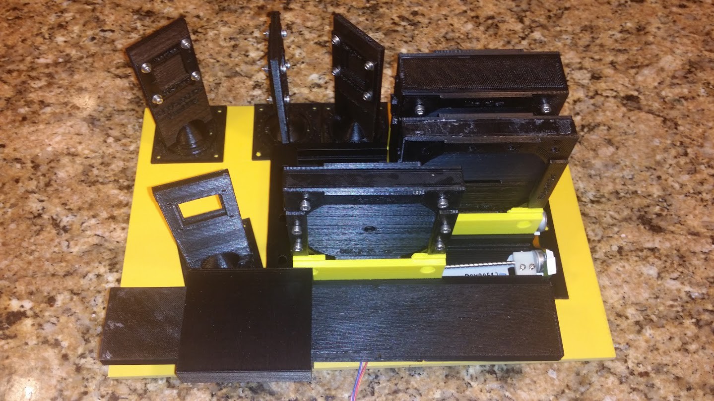
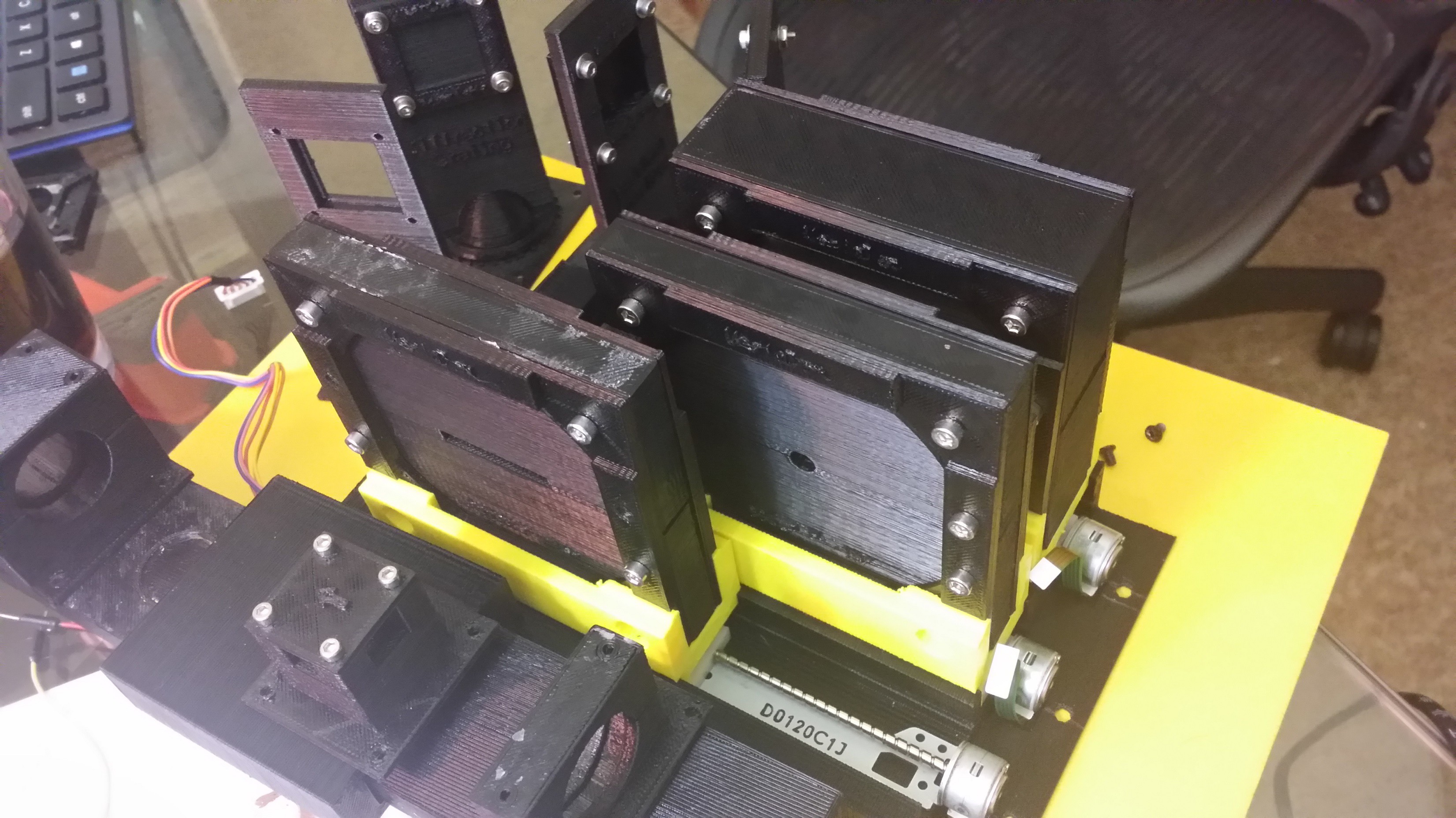
Top down look..(cuvette tray and gearbox in foreground, 550nmLP filter in foreground-not where its supposed to be, 522nmSP filter in the middle-not where its supposed to be either...the mirror mount before its present state in the middle back, the vertical aperture to its left and the diffraction grating in the far left corner before it's future state..)
![]()
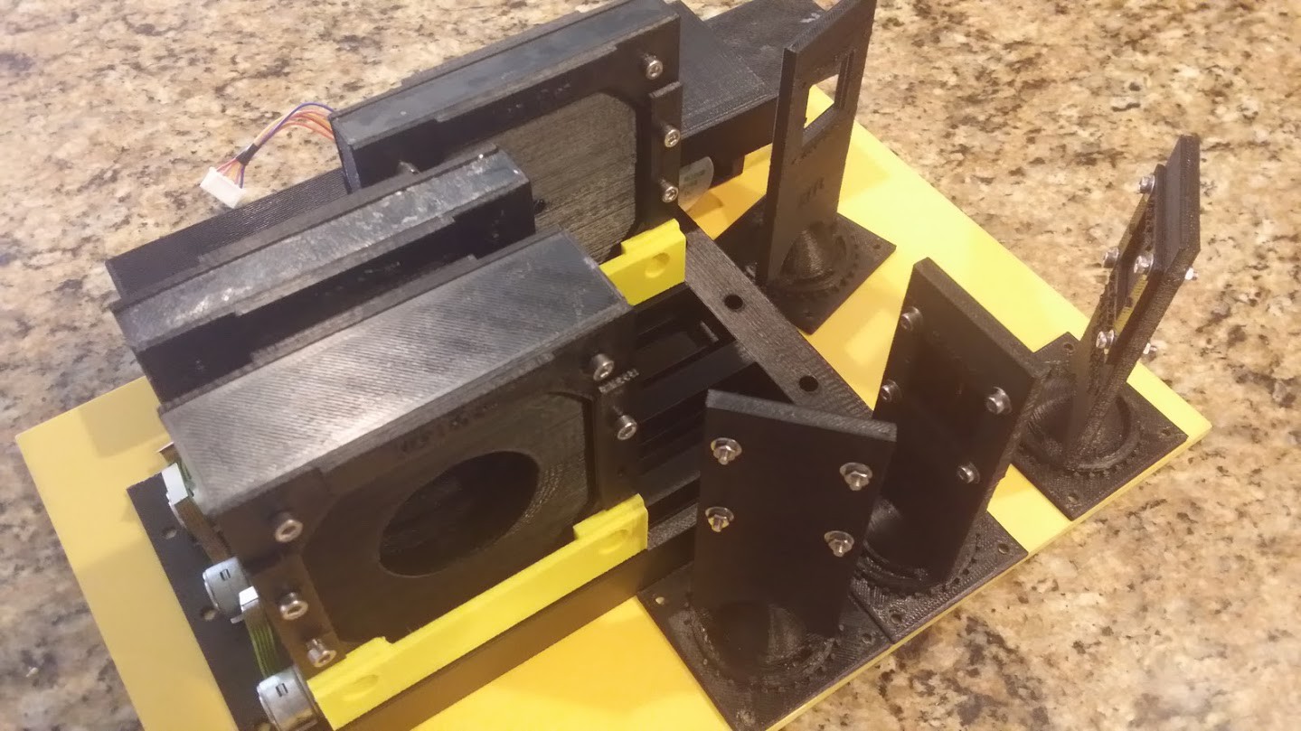
Another angle.
![]()
Yet another...
![]()
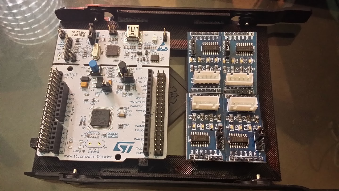
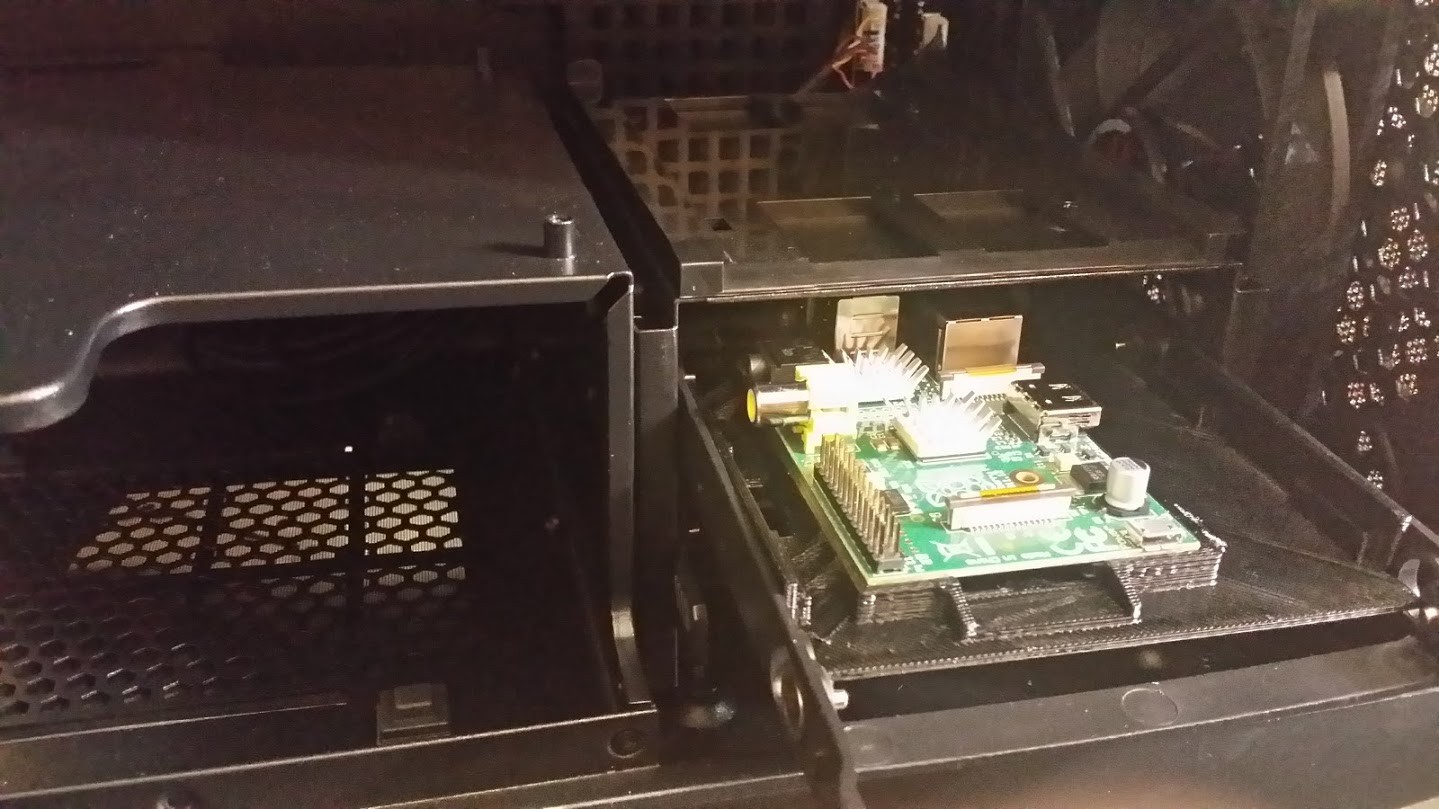
The ST Nucleo (arduino compatible) board and the stepper controllers(uln2003s soon to be replaced)...All mounted in a 3.5" drive tray with a 3d printed adapter plate to slide into the drive rack in the case..
![]()
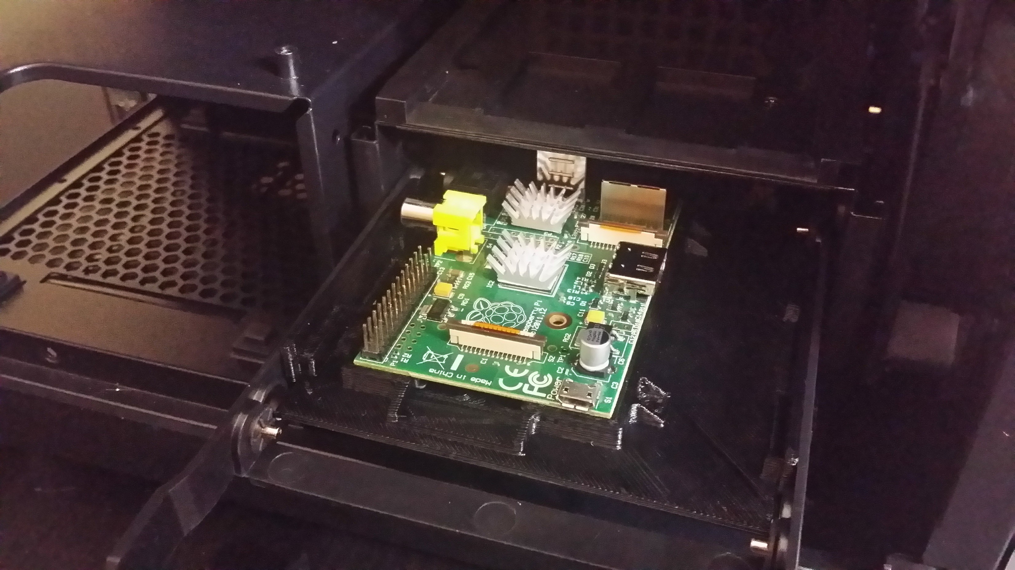
The raspberryPi sitting snugly in its adapter plate ready to slide into the drive cage above the nucleo board.
![]()
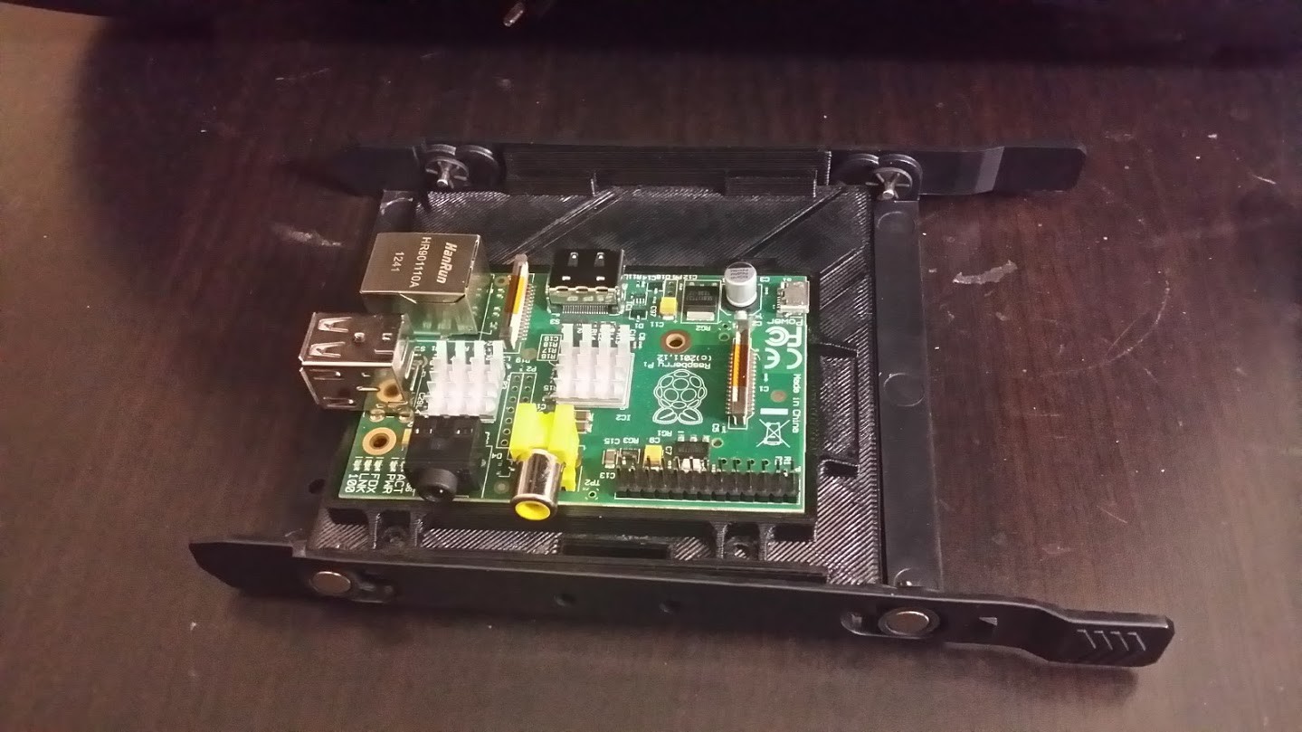
Another angle of the raspberryPi...
![]()
A view of the raspberryPi in its adapter plate...
![]()
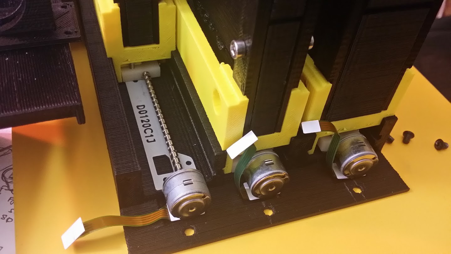
A closeup of the linear stepper motors for the filter adapter tray...
![]()
Another angle..
![]()
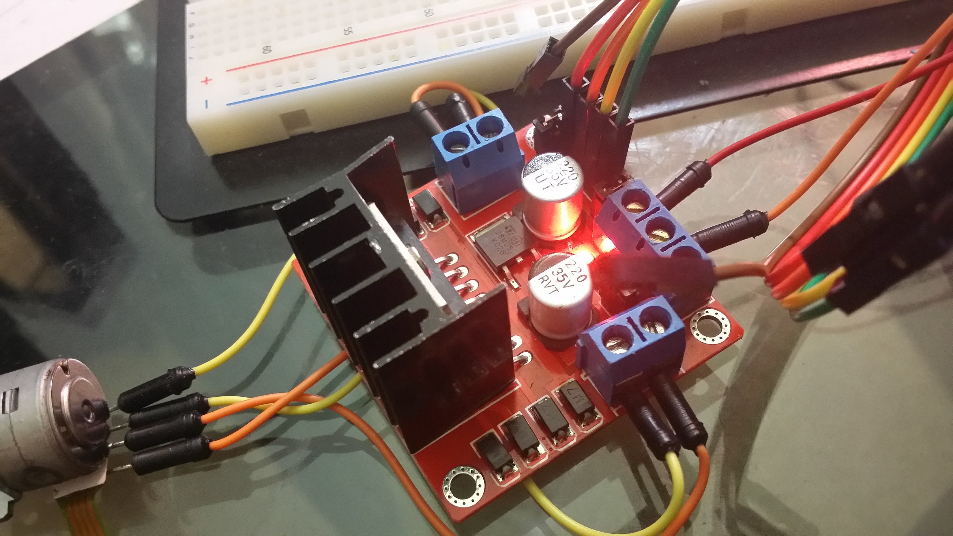
The HBridge hooked up to the linear stepper and the nucleo for testing...
![]()
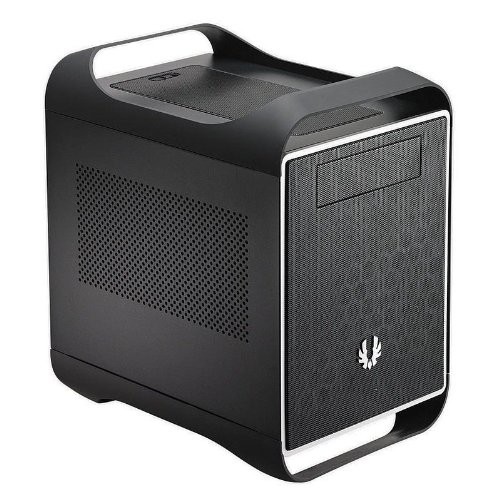
The case all this is going to fit into... I'm debating on how to handle the cuvette tray slide...unfortunately I can't use the 5.25" drive bay...the cuvette is too tall...
![]()
Update: Tested the TFT display.. works great..!
![]()
-
3D Printed Parts So Far...
06/03/2014 at 06:12 • 0 commentsI just wanted to break out and show the parts that I have and the status on their completion.. I have printed all of these objects and will soon post a side by side comparison of the rendered object and the actual object.. They all came out great in my opinion..I'm quite satisfied with the DaVinci printer... I used to use a rostock but am in the process of converting that to a pcb mill... more on that one later! So here we go....
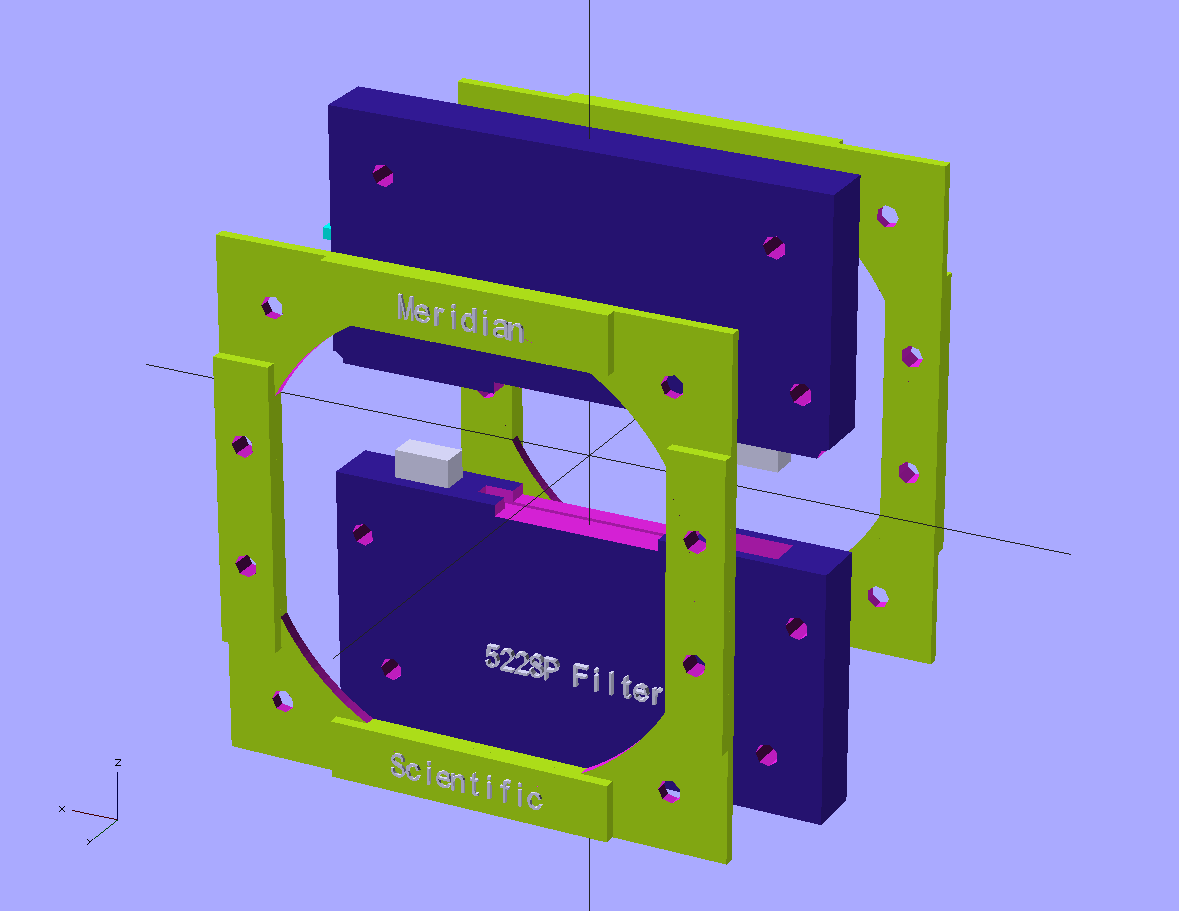
This is the 522nm Short Pass Filter Mount with its brackets... The filter I purchased is a rectangular piece and fits nicely in here.. The brackets are bulky because they are modular (and can be redesigned to fit whatever shape filter you get from eBay.. and the bulky mount allows for keeping the lens at the correct height to intersect with the beam)..
![]()
Here we have the 532nm Pass Filter mount... which is considerably shorter than the bulky filters in the sliding tray because it sits on the top shelf with the laser emitter and is the correct height to intersect there. All of these mounts are customizable to fit whatever lens you score off eBay..Mine's 1" round..
![]()
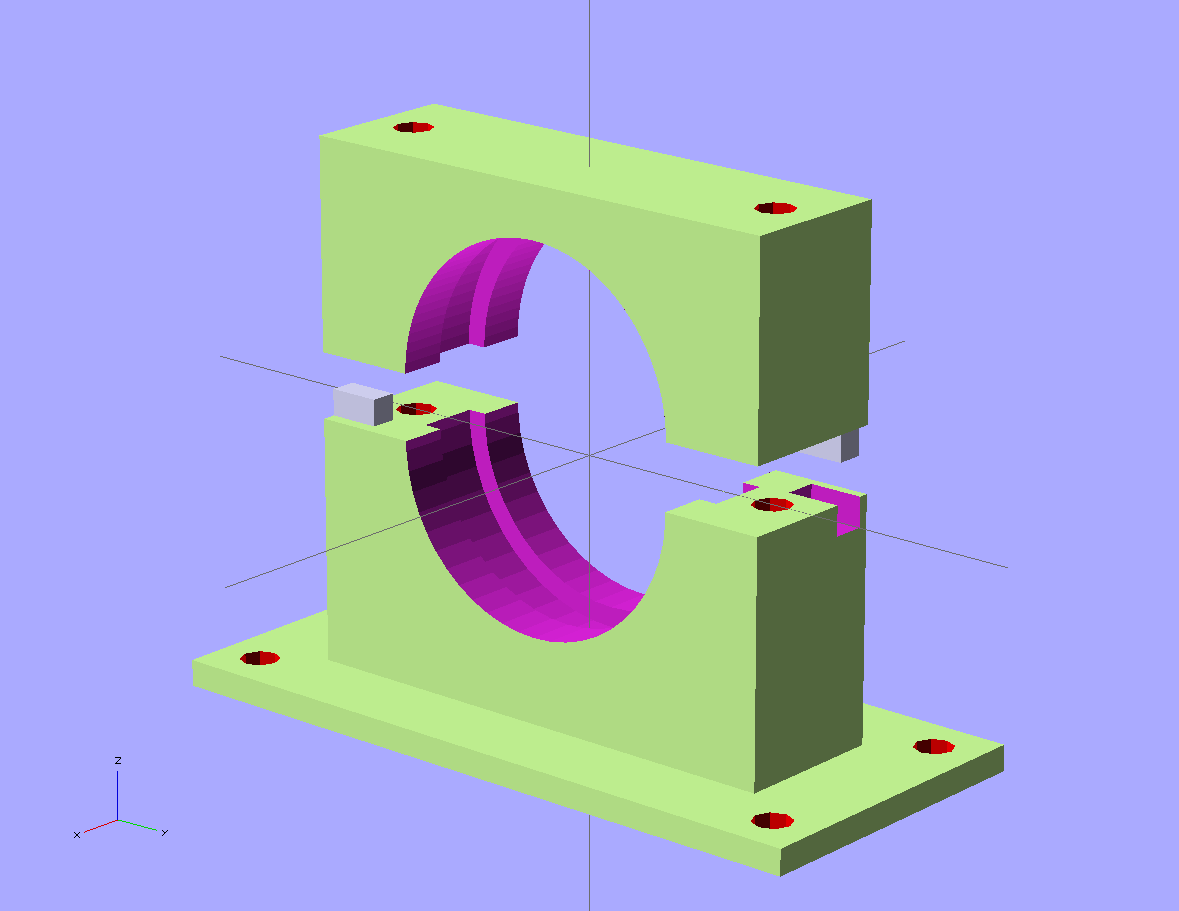
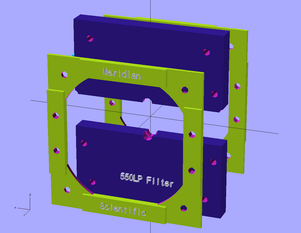
Here we have the 550nm Long Pass filter mount.. Also bulky to fit into the tray assembly.. Mine is a pretty small 12.5mm diameter lens so this is mostly mount...
![]()
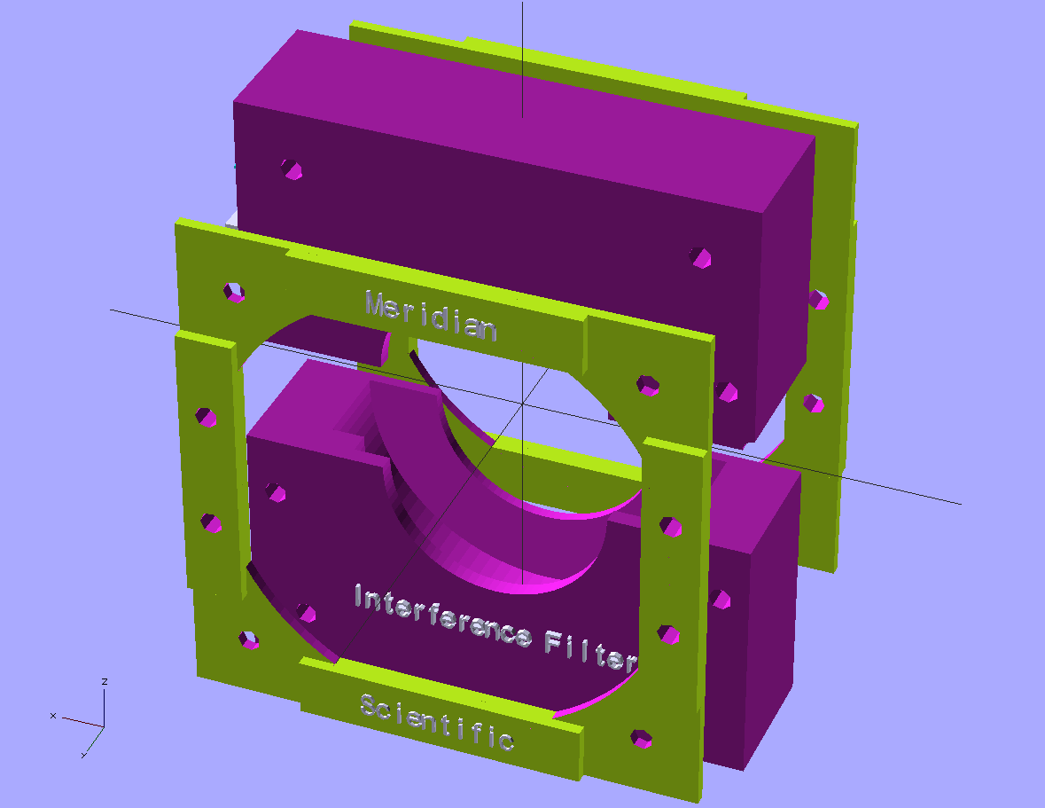
And for my 3rd lens..I decided to first experiment with an interference filter.. I scored one that is 40mm diameter..the biggest lens in my system.. And here's the beauty...the 3rd lens is also modular, meaning you can stick whatever you want in there with only having to modify the mount, not the brackets or anything else..
![]()
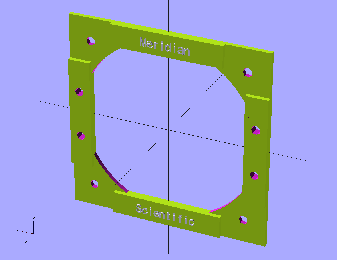
Here is the retaining bracket for the filter mounts...
![]()
This is the first idea for the cuvette tray.. I wanted an assembly that would open sorta like a cdrom tray though a hole in the front of the case..allowing you to just drop the cuvette in a square hole, and push a button...were it would be pulled in and analyzed...I printed this, mounted up a stepper motor...it works great...not sure if this will end up in my final design...
![]()
The tray itself is printed in two halves with the rack on one half...because my printer only does 200x200..and this all comes out slightly larger than that..
![]()
This is the beam splitter mount.. pretty simple...the cube beam splitter is just that...a 12.5mm cube of glass that splits the beam...it sits right in the middle and is held in place by the top..
![]()
Here is at least a temporary solution to holding the collimating lens...I designed it so it's three parts...the gray face and back....and a standard retaining bracket to hold it together...I did it this way because I needed to save space and also hold the lens at its focal length from the vertical aperture. I will probably change this.
![]()
This is my placeholder for the diffraction grating mount.. I haven't gotten this far yet..so I put this in here to make room for it.. This will change...soon.
![]()
This is my first surface mirror mount.. the retaining brackets are connected through a tunnel and float inside the mount on a spring loaded mount that should allow for making small adjustments to aim the mirror correctly through the vertical aperture. I'm still working on this, and it may change..but it seems ok for the most part..The most challenging part I've designed so far to print..
![]()
Here is the microscope objective lens mount... Worked perfect the first time...I added the notches to make it better.
![]()
And the optics mount standard retaining bracket.. prints nicely.
![]()
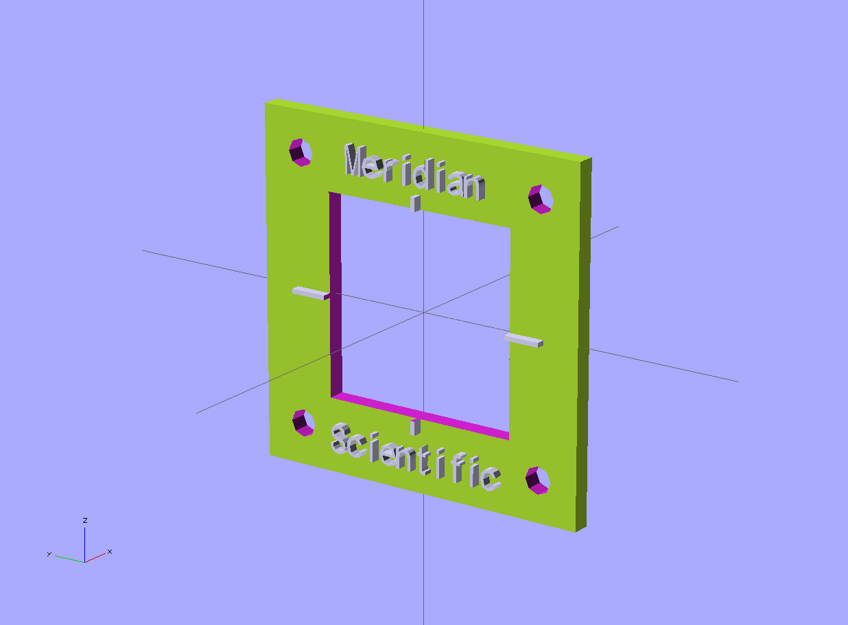
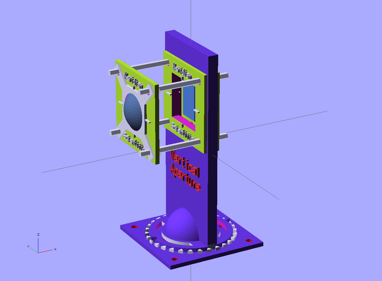
Here is the vertical aperture with the collimating lens mounted in place... this will probably change...
![]()
And a few shots of what I have so far from a couple different angles...I think it's coming along nicely, and the printed parts look just like this..(I'll post pics soon)..I printed them in black, with some yellow highlights..
![]()
![]()
![]()
![]()
![]()
-
Cameras
06/02/2014 at 09:23 • 0 commentsI've been looking at options for which camera to go with so I can get the images from the grating... I am leaning toward modifying an existing webcam so I can take long exposures...(this will allow for getting a better image since the return light passing through the filters, etc. will be fairly weak.) . So, a little googling lead me to http://www.pmdo.com/wwhich.htm which has a great list of mods people have done to cameras for astronomy... Looks promising...
The other option was to use the standard raspberryPi camera board.. This became less appealing after investigating the exposure settings and testing with a small spectroscope in the lab... Not great... Ok, but not great...and some googling lead to finding some difficulty they've been having with longer exposures.....I'd like to use it, but if I do...I might actually go with the infraRed version for a secondary setup where I can take IR exposures in addition to the regular stuff...
The cameras listed on the above link, mostly seem pretty lo-res, older cameras...I'm still pretty early on in looking into this, so I'm going to do some more reading and see if I can just mod a camera that I like...I don't know if webcams are like the ccd's they use in astronomy, where they need to be cooled, etc. for long exposures, but that shouldn't be a problem..
More on this soon!
Update: I think image stacking is probably looking more attractive at this point..
Update: Looks like I'm thinking the raspberryPi camera module is still a good option....shooting high frame rate video for a period of time...then splitting that into a number of images, then stacking those to create one simulated long exposure image for further processing... I will experiment with this approach soon...
-
Added the collimating lens bracket..
05/31/2014 at 05:04 • 0 commentsI created a bracket that attaches to the rear face of the vertical aperture that will allow fine tuning of the focal length for the biConvex (collimating) lens.. This will allow the light that is passed through the vertical aperture (slit) to be focused properly on the surface of the concave grating mirror. ...which will in turn allow us to get a nice crisp image with the camera!
![]()
![]()
-
Right now it's mostly about the 3D...but a little about microcontrollers too...
05/30/2014 at 20:41 • 0 commentsI have been working..day and night for the past couple weeks on getting the 3D parts designed and tested out.. I have a number of objects created (as you might see in the gitHub repo), some of which need minor tweaks... But mostly, progress is coming along pretty well.
I recently redesigned the mirror mount to have a floating cage that holds the mirror allowing you to adjust each of the 4 screws to fine tune where the mirror is pointing..should help..
![]()
I'm working toward keying the tops and bottoms of all the mounts to make for a more secure fit..
![]()
I also redesigned the 532nm pass filter mount to accommodate the new pass filter I purchased...(sometimes eBay doesn't pan out as well as one would hope..the original I bought was damaged because the seller taped the filter to a plastic bag...ruined the surface..the new one was shipped extremely well in a huge box of its own..)
![]()
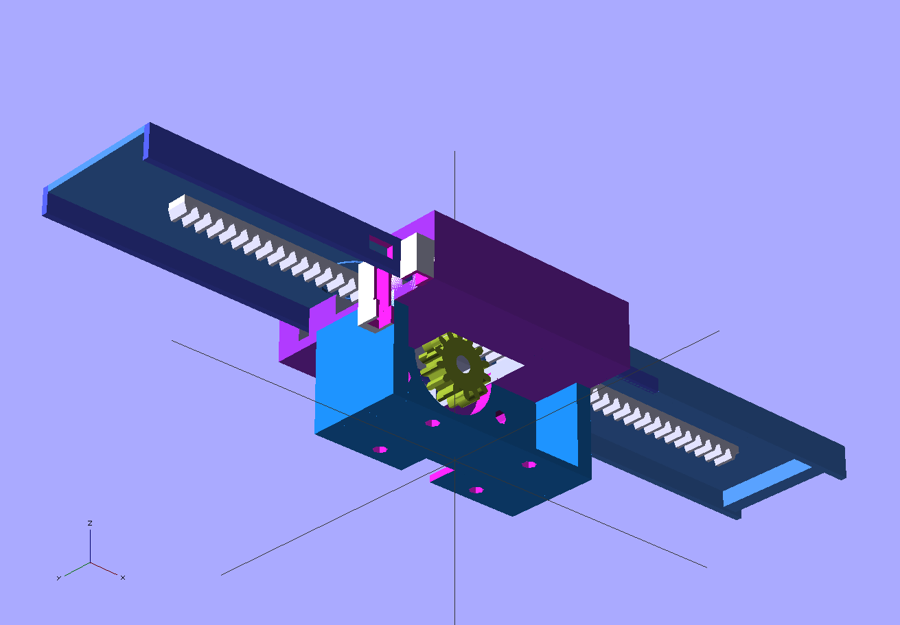
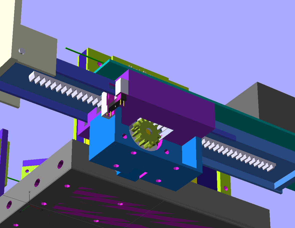
I also recently tested the sliding tray mechanism with the 3D printed gear and rack for the cuvette tray..
![]()
This will allow the cuvette holder to slide out like a cdrom drive tray.. Works great on the MSP430 I tested it with, now I have to move on and put together everything for it to work on the real micro I am using for this...which came yesterday from Mouser...
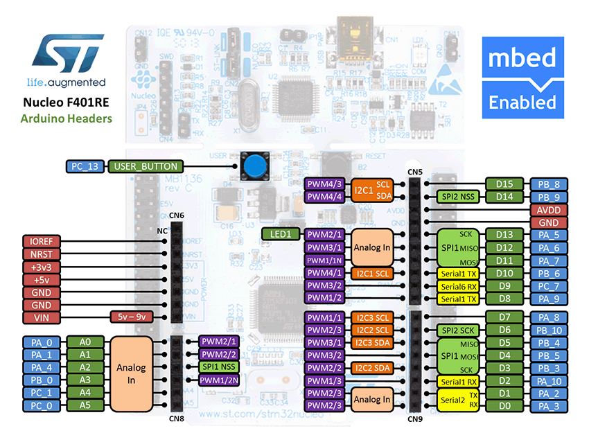
It is the ST Nucleo F401RE...one of the many mBed compatible dev boards..
![]()
http://mbed.org/platforms/ST-Nucleo-F401RE/ You cannot beat it for $10 from mouser... I love the mBed platform actually, and yes the online IDE... I'm horrible at data storage and my code is safer in the cloud...and no, I've never run into the site being down, etc.. http://mbed.org/ worth a look.
ramanPi - Raman Spectrometer
The open source 3D Printable Raman Spectrometer using a RaspberryPi and easy to find off the shelf components..