The controller board seems to fit well in the enclosure base. (The enclosure is from Bud, model CU-18426-W )
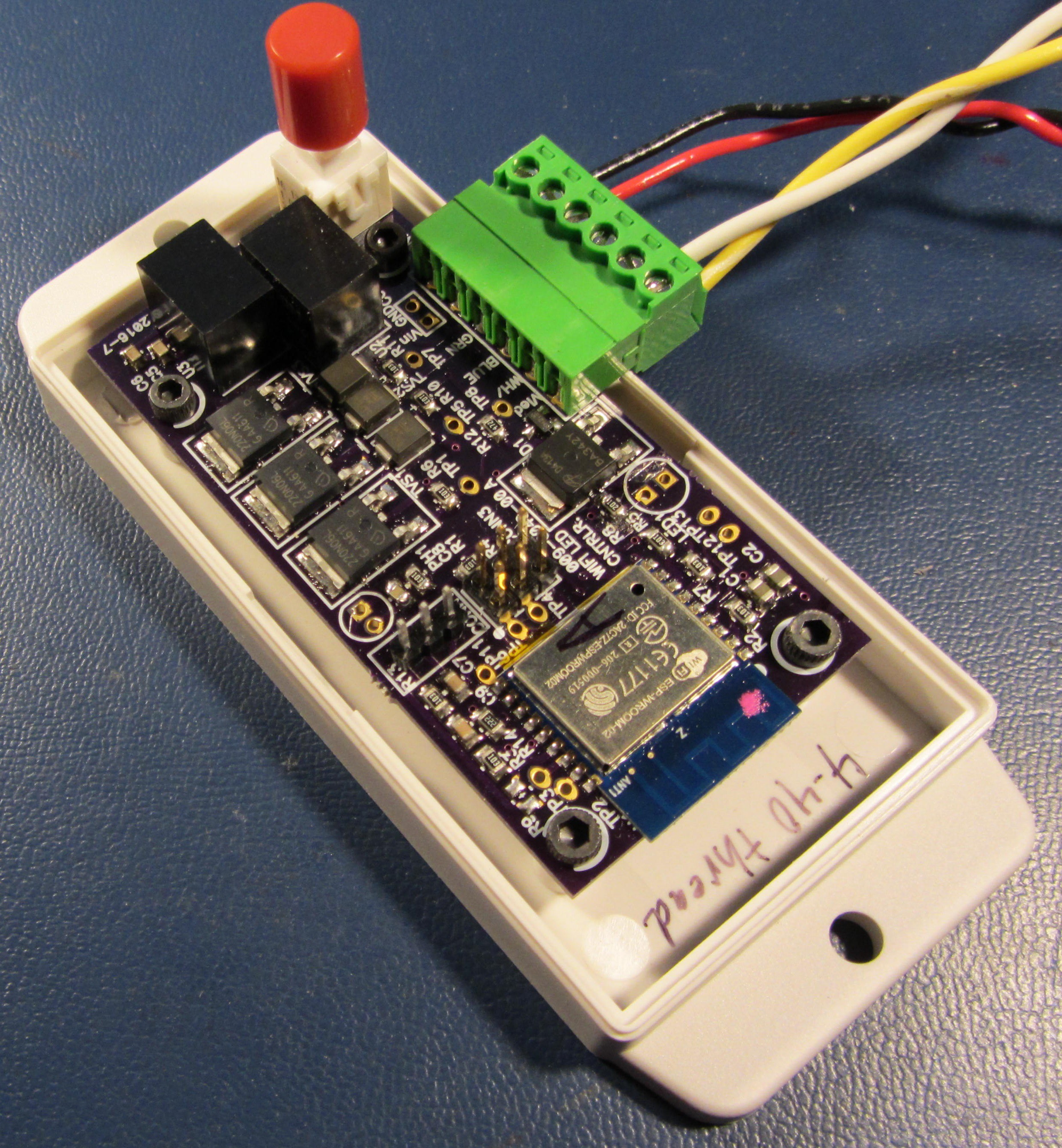
Figure 1: The enclosure (with flanges) and the controller PCB
The
red and black wire in the above image is the 12VDC in. The yellow
and white wire is anode and cathode leads going out to my LED load.
I'm really a big fan of the red push button. I should to to work it into all of my future projects. :)
I need to post a video sometime of the unit operating.
Discussions
Become a Hackaday.io Member
Create an account to leave a comment. Already have an account? Log In.