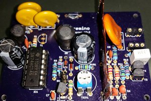
This design is for a very simple AC phase control circuit. There is however no isolation between the low voltage side and AC side of the circuit. You have been warned and anyone attempting to build this circuit does so at their own risk. If you do not know what you are doing, please do not attempt to build this circuit. There is the very real possibility of damaged components, fire, or injury to people and property if not done correctly.
Now that that is out of the way - this project is for those who don't want to spend over $100 for a digital/analog controllable AC phase control device. I have laid out a circuit and PCB which is available in Eagle format via the Dropbox link. The PCB is designed to handle up to about a 30A load (assuming 2oz copper/sqft PCB, 80F ambient, 20F max temp rise), however the current design uses a 24V rated triac to leave a little overhead on what the PCB traces can handle. Zero crossing is detected via a 1M ohm resistor to AC HOT and a 1M ohm resistor to AC EARTH. The resistors act as a current limiter (so you don't fry the MCU), while the internal clamping diodes on the atMega 328P clamp the voltage between VCC + 0.5V and GND - 0.5V. This design is per Atmel's application note AVR182, available here
http://www.atmel.com/images/doc2508.pdf.
The zero cross detection is tied to INT0 and simply increments a global counter variable for each falling edge detected. While more robust circuits use an optoisolator and support passives to detect both zero crossing events in a full AC cycle, this circuit only detects one zero cross per AC cycle. This requires a little extra work in software to trigger the triac on both half cycles, but also reduces the overall circuit cost.
To further reduce circuit cost, I am also using a triac that is triggerable directly from an MCU pin and eliminating a second optoisolator and support passives. As the device I intend to use this with (my CNC mill), has a regulated 5V supply available, I have also neglected to include a 5V power circuit and power must be supplied from off-board.
The circuit accepts a digital tach input on INT1 for closed loop operation. This can be supplied by an infrared optical pickup and a bit of white paint on the motor shaft, and hall effect sensor and a magnet on the shaft, or any other sort of tach encoder you have available. I am coding assuming a single pulse per revolution of the motor shaft, however I intend to make the PPR easily adjustable. I however do not intend to support quadrature encoders.
Input from the CNC controller will be PWM to ADC1, which is easily supported from the most common CNC control programs (Mach3 and LinuxCNC). Other control methods are possible, but I do not plan to support them myself.
All of this on a 2.4"x2.4" PCB for easy ordering from SeedStudio or your PCB house of choice on the cheap!
The firmware will be written in Arduino for easy maintainability and modification, and everything will be open source. I plan to use off the shelf libraries and code as much as possible to make things simple. If anyone has made it this far into the details and knows of an existing open source AC phase control firmware I can fork for this circuit, please let me know!
As always with my projects, comments, criticisms, and suggestions are always welcome!
 Rhys
Rhys


 Michael Frank Taylor
 harertatesfa

 Nikolai Ovesen
While it's clear that you've put thought and effort into the project, I'd like to emphasize the importance of safety when working with AC current, especially without proper isolation and precautions. Directly connecting household AC current to an MCU pin can be extremely dangerous and can result in electrical hazards, fire, and potential injury. Without proper insulation and isolation, there is a significant risk to both the person attempting to build this circuit and the devices connected to it. https://www.paybyplatema.ltd/
I strongly recommend against attempting to build such a circuit without the necessary safety measures and expertise in electrical engineering. If you're looking to control the speed of a motor in a CNC tool head, there are safer and more reliable methods that can be used, such as commercially available motor speed controllers or designs that incorporate appropriate safety mechanisms and isolation.