 Vinch
VinchThe first expansion board is ready and seems functional.
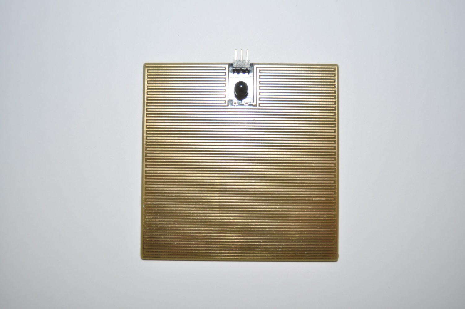
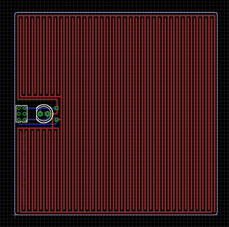
Only 2 components need to be soldered: the 6-pin header (male) to be plugged on the main Triggy board, and the light sensor. The remaining part of the board is the rain/water sensor. It is composed of an anode and a cathode with interlaced copper traces (spacing ~0.5 mm). This allows first the first drop of water to be detected. This has been confirmed by measuring the resistance between the 2 inputs.
The dimensions of this board are 7 cm x 7 cm. This area is a good compromise between cost and ability to quickly detect when it starts to rain.
 Some resistors need to be put in series with the two sensors: theses have been soldered on the Triggy board. We measure then a variation of voltage through the ADC available on the nRF52832.
Next step: develop the firmware to support these new sensors and trigger an action on the next rain.
Discussions
Become a Hackaday.io Member
Create an account to leave a comment. Already have an account? Log In.