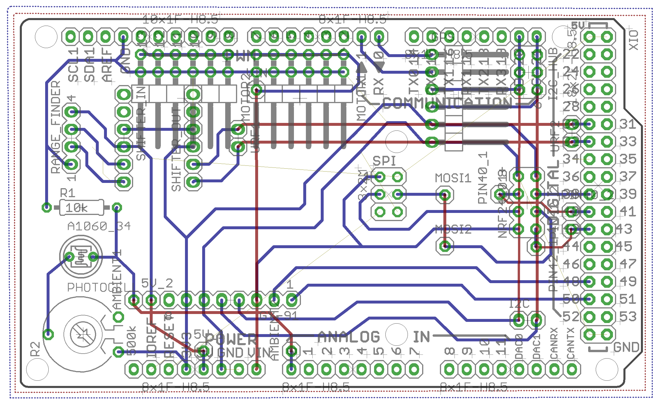
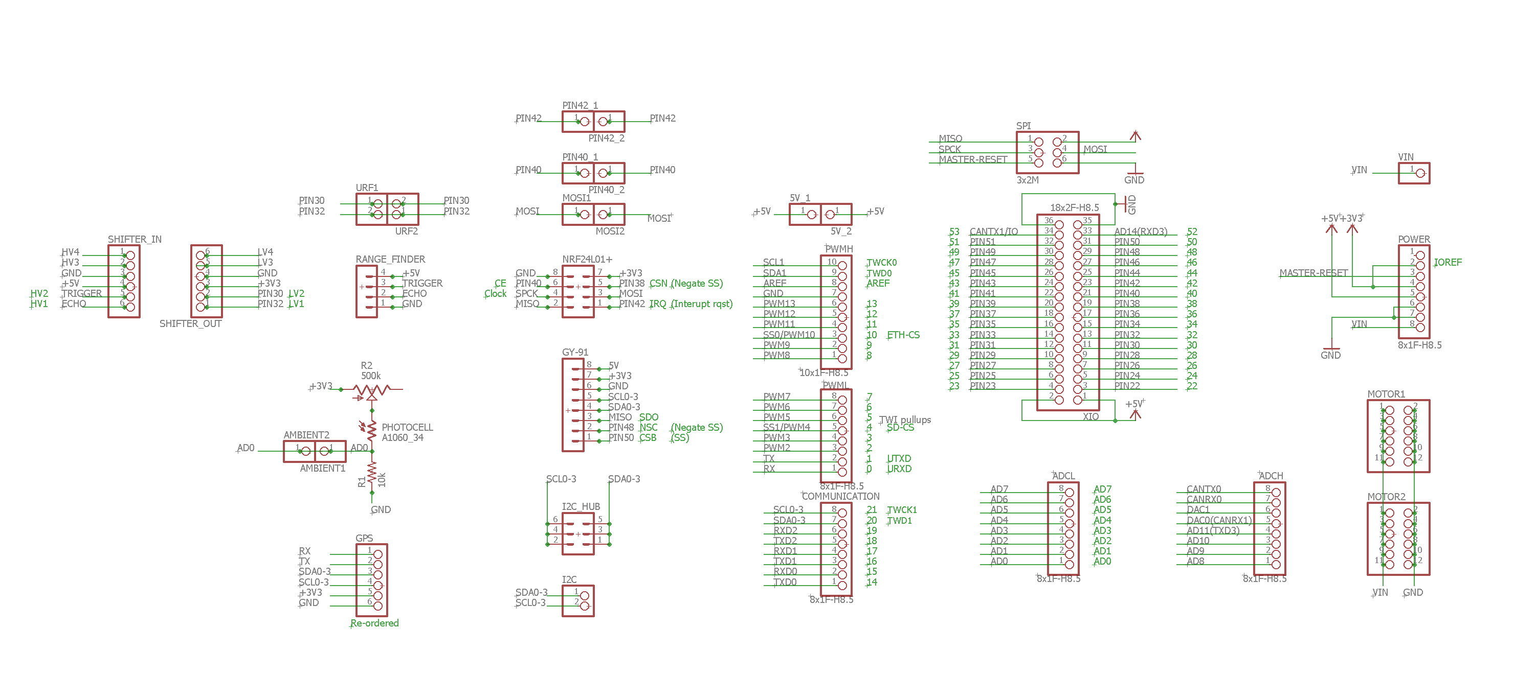
I have started to design all the components into a PCB with all the sensors tha i could of think of that will be usefull. I am going to mill in using the othermill so i had to make the wires spread apart, the red wires will be connected manually since i have only one sided PCB's.
** I would love to hear you thoughts, if you have any ideas for new sensors or any suggestion please let me know. (all the component are listed in the project page).
Stage two: desgining the flight controller
A project log for Unique mini quadcopter
fully designed mini quadcopter for special applications unique body, microcontroller and flight controller software
 Benny
Benny

Discussions
Become a Hackaday.io Member
Create an account to leave a comment. Already have an account? Log In.
Missing 2nd pad for jumpers to GY91 connector, I2C. Those pads would be needed if you want jumpers on component (top) side.
I would use thicker trace and larger pads to through hole connectors as they see more mechanical stress when board flexes under vibrations.
Are you sure? yes | no
Thank you for the advices!
I have enlarged all the traces as you suggested, but not the pads (since that cause me a lot problems unfortunately) maybe you knowa pre-made library that I can use?
I didnt understood what you said about the jumpers, are you suggested adding jumpers to the GY91 I2C pins so i could disconnect them if I wish so?
Are you sure? yes | no
Are you using eagle cad? Pinhead is the name of the library. They have elongated pads in the library and the extra copper are should help with homebrew PCB.
Are you sure? yes | no
You might also want to move these two vias down as they will be interfering with your 90 degrees header.
Similarly, Shifter_In and out are in the shadow of the two connectors.
Are you sure? yes | no
Yes, I am using eagle and I have used the Pinhead library.
I managed to enlarge all the pads as you told me.
I didn't knew that component represent 90 degree header, I gonna use normal header in there and the other connection is raised over the board so I dont think I will have a problem connecting it.
Thanks for sharing from your experience!
Are you sure? yes | no