 willbaden
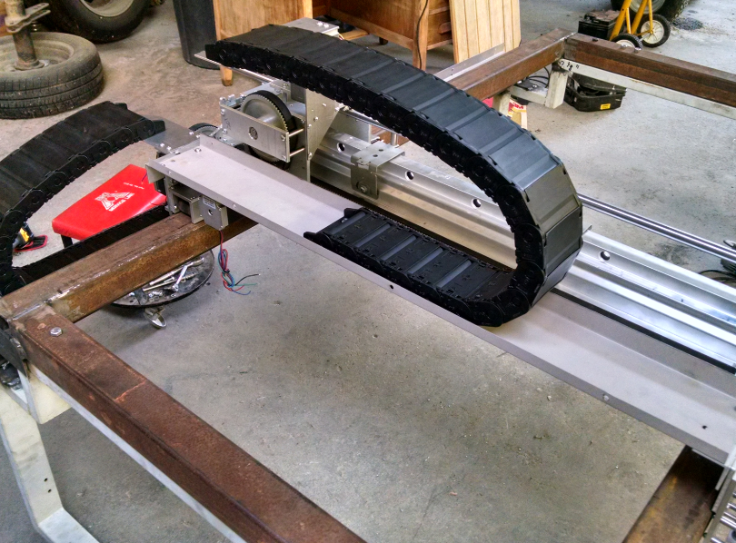
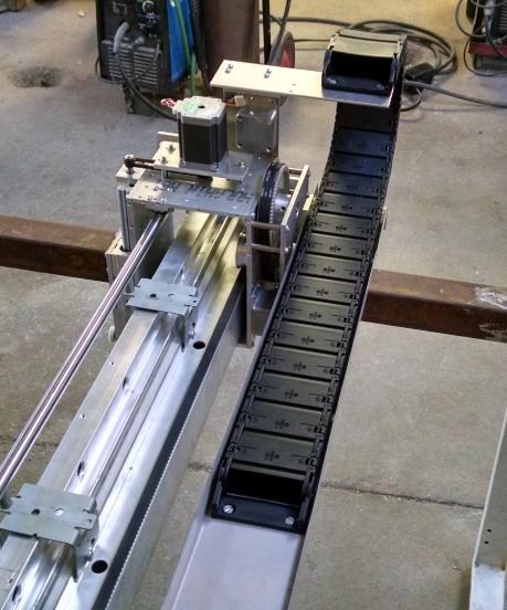
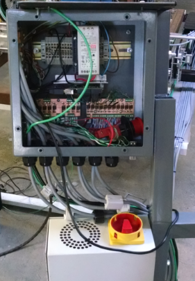
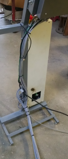
Cables were routed between the controller box and driver box to the steppers and limit switches using enclosed IGUS cable carriers. The Y axis carrier carries the bulk of the cables while the X axis carrier is considerably less.
Mocking up the cable carriers was roughly done with kant twist clamps.
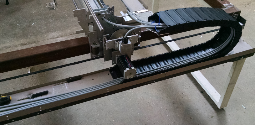
The tray that the carrier sits in for both X and Y axis was sheet metal taken from some high school lockers that were being thrown away. They were cut using the handheld plasma cutter that is now used on the CNC. To bend the 90 degree angle lip, some long angle iron was used.
The tray was held up using some angle iron that was pulled from a bed frame. Once satisfied with the location, the carrier was fastened to the tray and carriage.
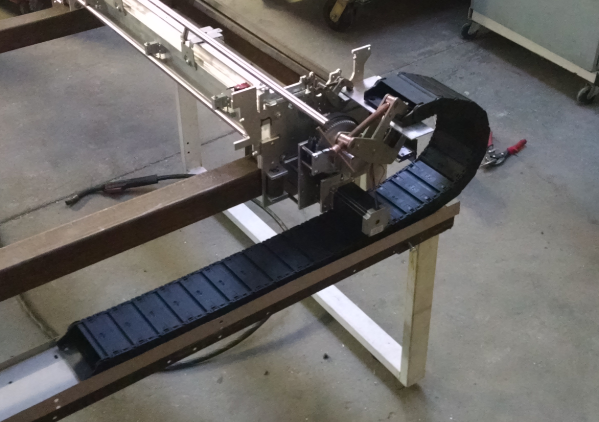
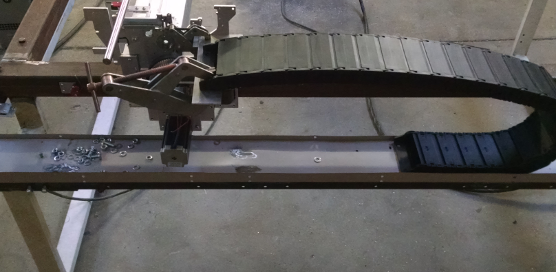
Below are a few pics of the installed x axis carrier.
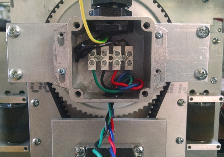
The Stepper motor wiring was then wired through. Some 5 conductor flex shielded cable was used. The fifth wire was abandoned since 4 wire bipolar steppers were used.
The stepper wiring was terminated in small diecast cases that had a terminal strip.
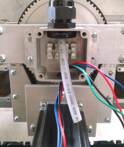
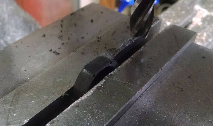
The strain reliefs barely fit into the side of the enclosure and required the nuts to be modified. Flats were machined for clearance for the bottom and lid of the enclosure.
The stepper wires then were terminated on the terminal strip.
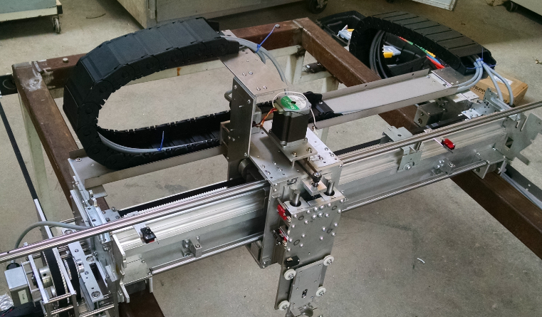
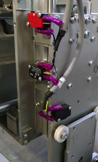
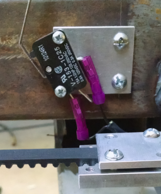
The limit switches were installed for both sides of travel on each axis. The Z axis had a third limit switch installed to act as the floating head detect.
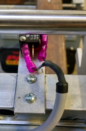
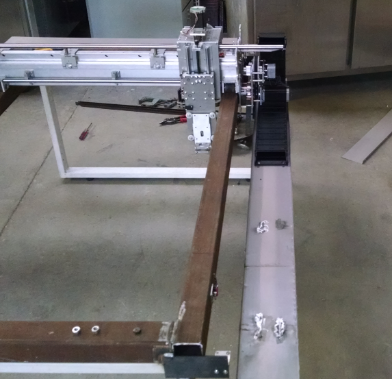
And the Y axis.
Discussions
Become a Hackaday.io Member
Create an account to leave a comment. Already have an account? Log In.