 forthnutter
I have setup a 1Hz clock signal to pin 1 to see what output pin are latched.
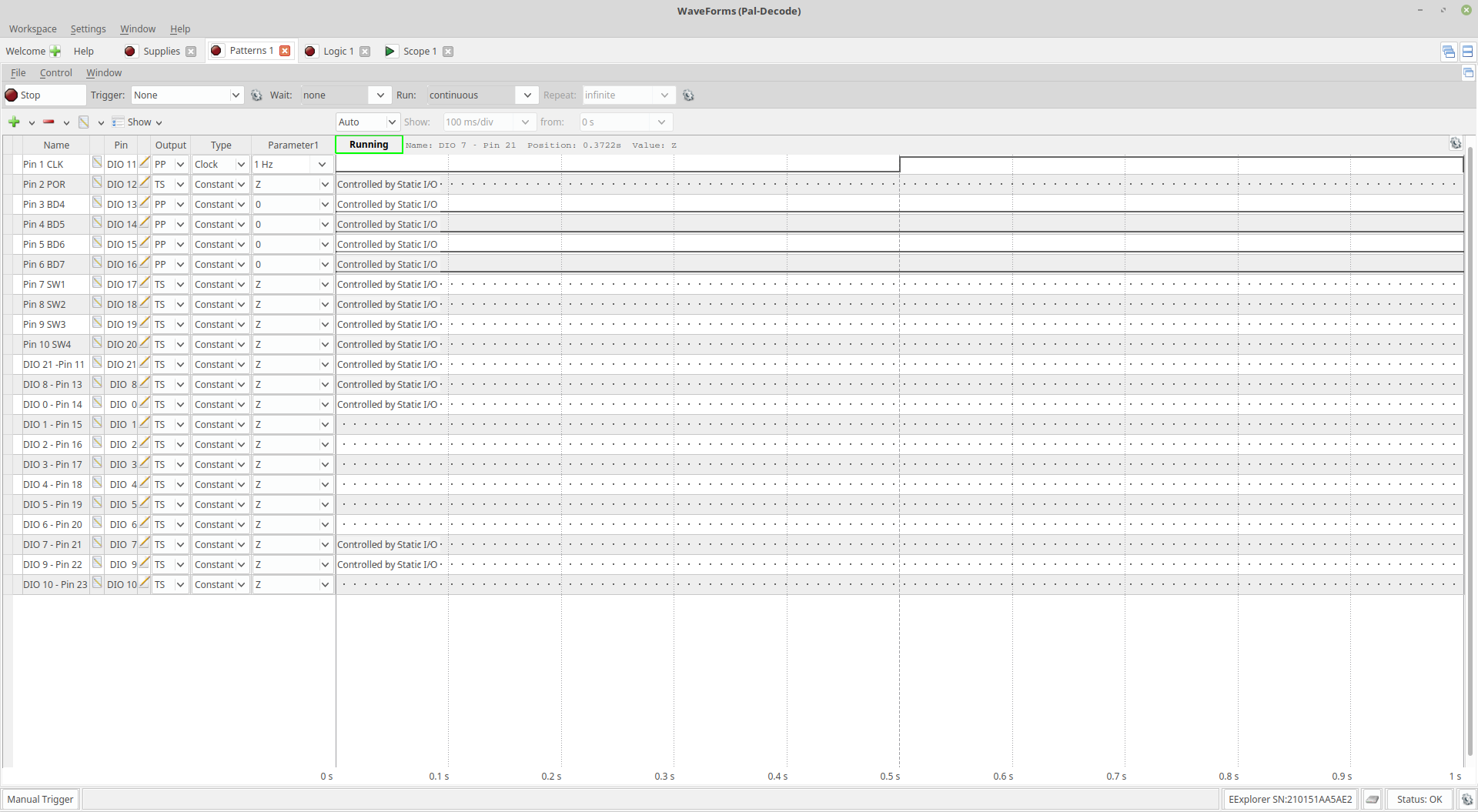
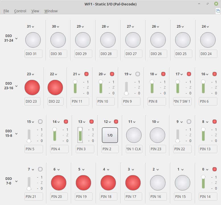
Then toggled the input on the Static I/O screen to see what changes and signals that changed on the clock edge.
A project log for WICE-4M
Leap Electronics WICE-4M EPROM Emulator Reverse Engineered
I have setup a 1Hz clock signal to pin 1 to see what output pin are latched.
Then toggled the input on the Static I/O screen to see what changes and signals that changed on the clock edge.
Discussions
Become a Hackaday.io Member
Create an account to leave a comment. Already have an account? Log In.