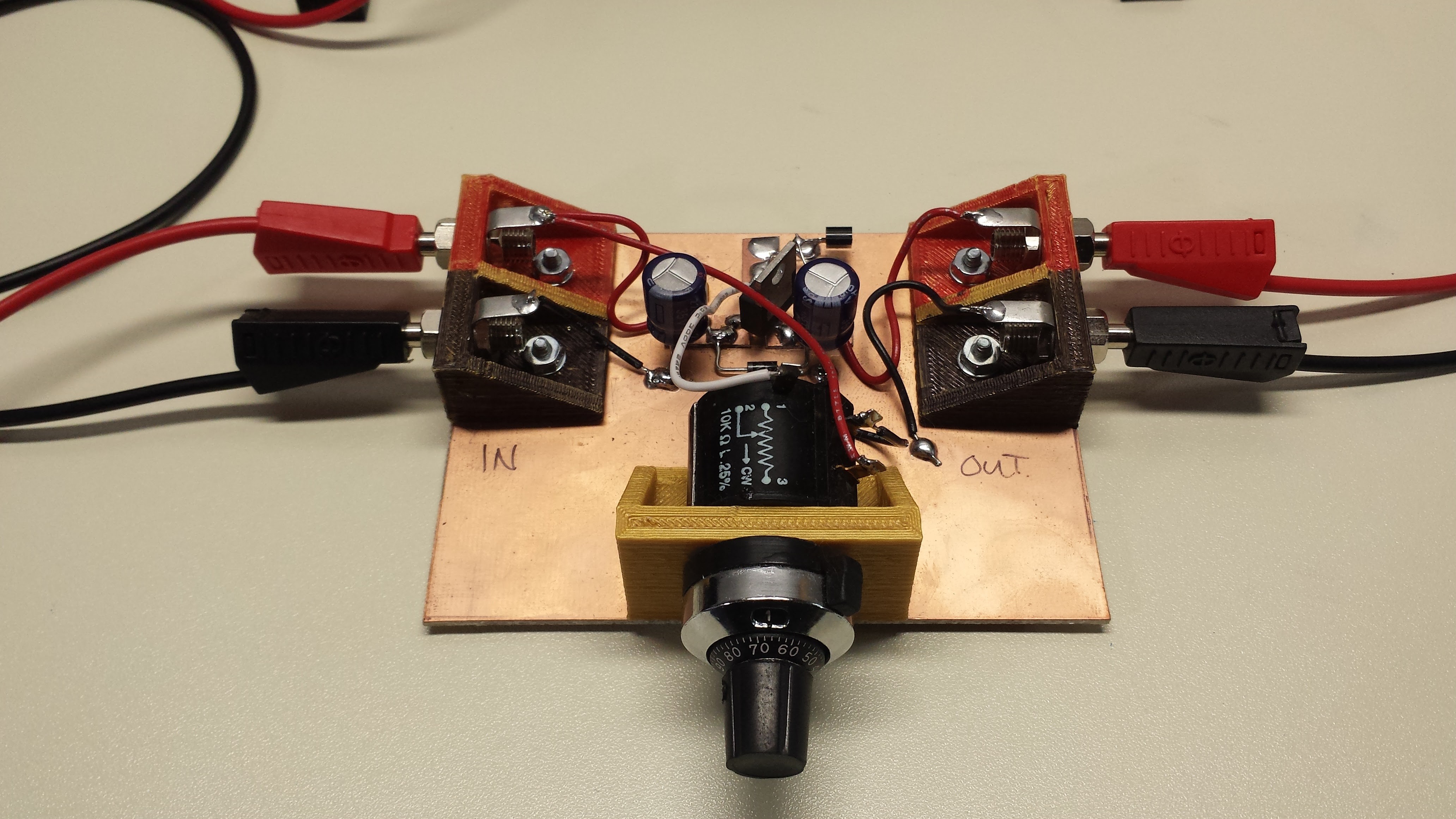
I decided to pursue an iterative design approach for this project rather than follow my instinct to guess at requirements and rush a design to the PCB house. This also allows me to get some data early and explore the subtleties of measurement, modeling and analysis. I re-cycled a finely-adjustable voltage source I had built for another project to do manual testing:

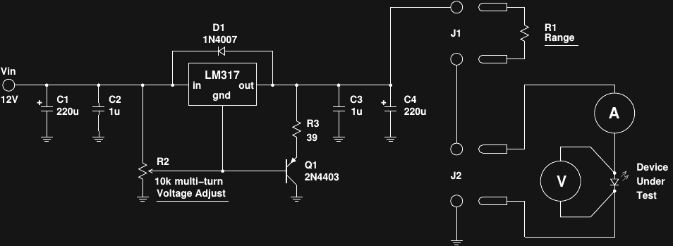
The circuit is basically an adjustable regulator using a multi-turn potentiometer. Here's the schematic:

(click here for a pdf version). R2 determines the control voltage for the LM317 regulator; the output is a nominal 1.25V above this reference. Q1 and R3 form a current sink based on this 1.25V difference to draw the minimum required current (about 10mA) from the regulator, so that devices can be tested below that level. Note that this circuit was designed to be used after a well-regulated lab supply; the reference voltage is derived from the input, so it would be very sensitive to supply noise. This module also works well as a regulator for testing circuits from 12V batteries. About the only drawback is that the LM317's built-in reference limits the minimum output to 1.25V.
R1 is used to transform the voltage output into a pseudo current source; it functions similarly to the ballast resistor used when driving LEDs from DC. Because all measurements are taken at the LED, the voltage output from this circuit and value of R1 don't need to be exact. R1 is chosen to select the approximate current range based on the nominal forward voltage of the LED. For example, if the LED has Vf around 3V, a 1k resistor would give an approximately (12 - 3) / 1k = 9 mA full-scale current range. Other resistors can be used for different ranges.
The meters here are standard DMMs, as shown below:

To gather data, the device-under-test is mounted close to the optical detector (VEML7700), the voltage is adjusted to give a desired LED voltage or current, then the values are read off the meters and the sensor. The data is recorded, and the next voltage is adjusted. This manual process is tedious and error-prone, but it works well enough if you only have one device to characterize. At last count, I have over a dozen waiting to be evaluated, with more likely to come.
This was the equipment and procedure I used to collect the data discussed in previous logs.
Lessons Learned
This seems like a reasonable approach to characterizing LEDs (and laser diodes). Automating this would save a significant effort. The LM317 plus resistor seems like a decent solution: driving the reference voltage with a DAC would provide an easy way to automate the control of the measurements. The built-in current and thermal limiting of the LM317 would be tough to beat at the same price point with a discrete version.
An analysis of how limiting the 1.25V minimum is in practice would be interesting. With the exception of maybe some IR LEDs, no optical devices will have a forward voltage this low. It might limit the testing of non-optical diodes, though, depending on the value of R1. I'll have to work through the numbers.
One possibility is to use another regulator, like the current-referenced LT3080, which goes all the way down to 0V. These are typically much more expensive than the jellybean '317. I drew an LT3080 in the initial sketch of the design, but I'm no longer convinced that it's required.
 Ted Yapo
Discussions
Become a Hackaday.io Member
Create an account to leave a comment. Already have an account? Log In.