(UPDATE 20160822: added addendum below)
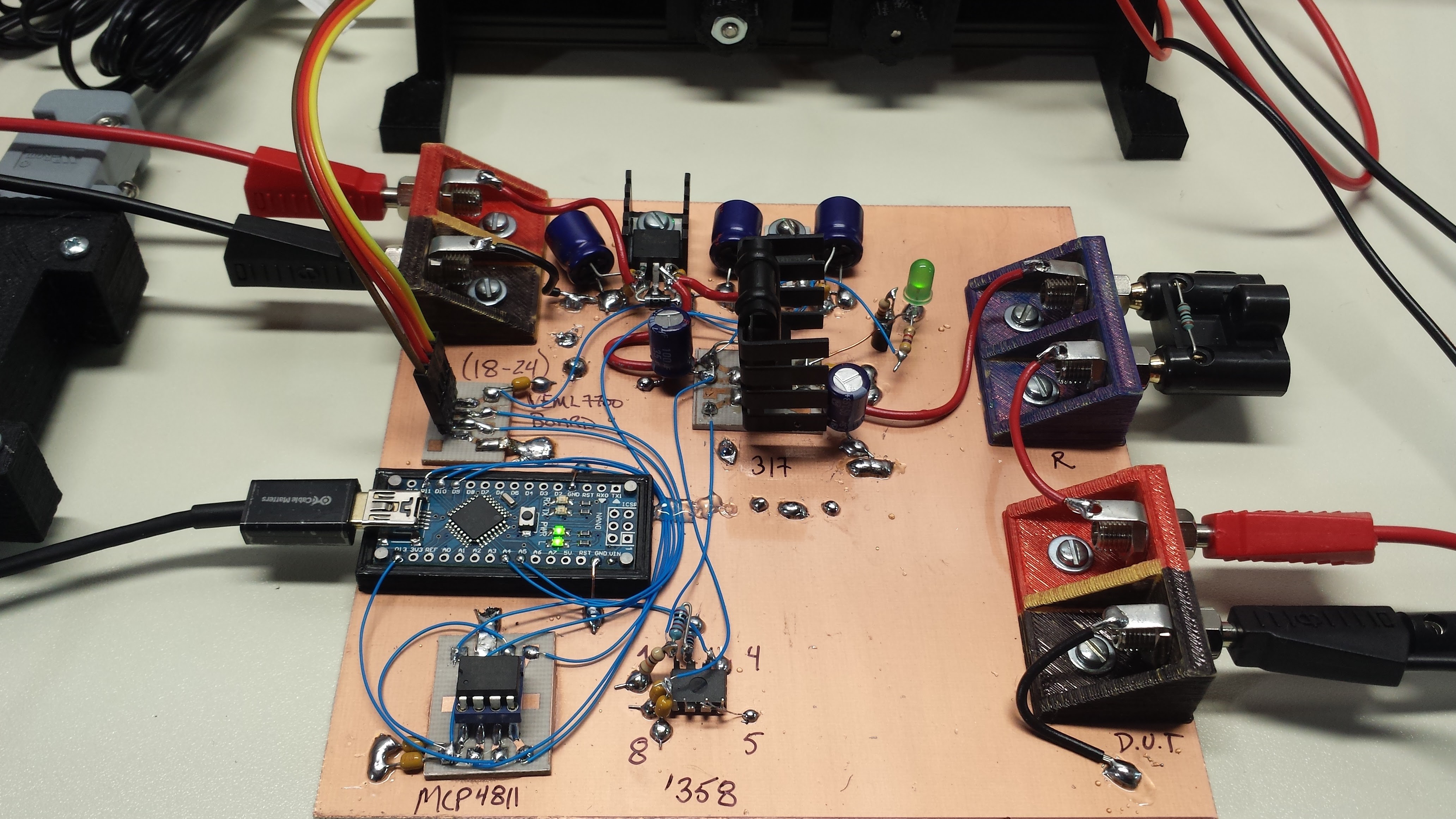
As a second iteration of the design, I built a prototype of an automated measurement system. The design may not be optimal, mainly because I just used parts I happened to have around. On the other hand, I've been quite pleased with the performance and ease-of-use so far. I assembled the prototype ugly-style on a piece of copper clad:

The basic circuit is the same as the manual design, except a 10-bit DAC drives the reference voltage for the LM317 regulator:

(click here for a pdf version). A pair of 7815 and 7805 fixed-voltage regulators provide the supplies for the rest of the circuit. The main component is again an LM317, this time with a DAC-generated reference voltage. The output of an MCP4811 10-bit DAC with internal 4.096V reference is amplified by a factor of 3 to provide a reference of between 0 and 12.29 V. With the LM317's nominal 1.25V added, the output range becomes 1.25 to 13.54 V. With 1024 levels, that equates to around 12mV steps.
The 3X amplification is provided by a jellybean LM358, because I have (100 - epsilon) of them. The '358 has an input range that extends to ground, but the output has difficulty sinking current at low voltages, so I added the odd-looking R6 as a pulldown.
The LM317 requires a minimum current of around 10mA to maintain regulation, so D1 and Q1 are used as a current sink across the output. Depending on the exact green LED used at D1, you may need to vary R3 a little to get around 10mA into the sink. 15mA might be a good target to shoot for, but I wouldn't go higher than 20, because the maximum dissipation on Q1 would then be (0.02 * 13.54) = 270mW, which is about all I'm comfortable running a plastic-cased transistor at (I usually divide the datasheet maximum dissipation by 2, in this case 625/2 = 312 mW would be a conservative max). D1 also serves as a power-on indicator.
The circuit is controlled by an arduino nano clone: the MCP4811 is controlled over SPI, while the VEML7700 light sensor board is connected via I2C. A simple program on the nano responds to two commands:
- "vdd.ddd" : set output voltage to dd.ddd. Responds with "OK" once voltage has been set
- "l" : sample VEML7700 light level. Responds with light level in lux after running the auto-ranging algorithm
The range-setting resistor, R1, is mounted in a dual-banana plug for quick range changes.
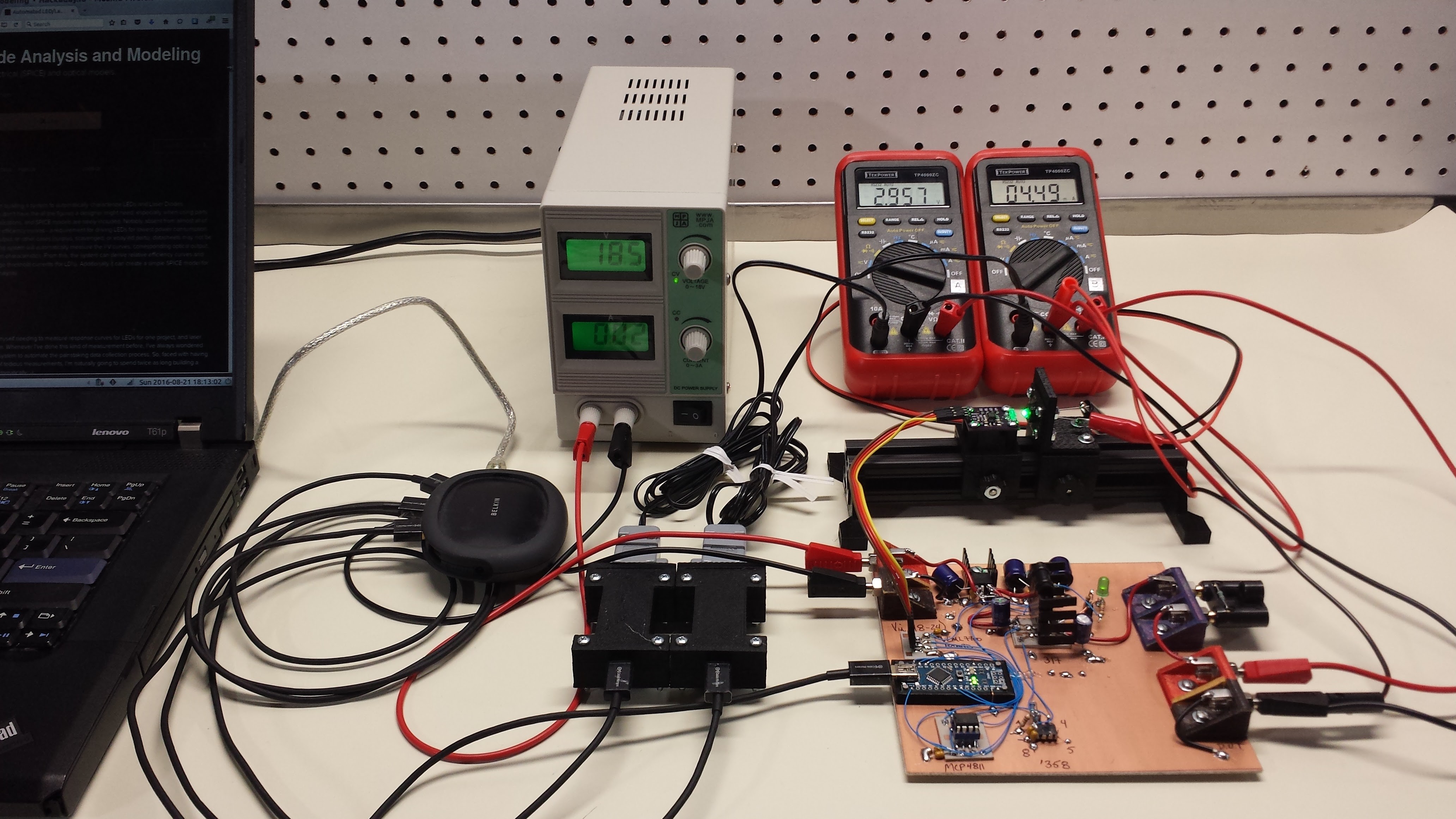
I left room on the copper clad for ADCs to do the measurement, but for now the DMMs work OK. Here's the system in operation (with the light-shielding cardboard box removed):

The particular DMMs I'm using have RS232 ports, so I was able to prototype the whole automatic measurement system. The problem with cheap serial DMMs, though, is the difficulty synchronizing them with other processes. I got so fed up with them that I did a whole project (quick as it was) just to solve this issue. Over on #TP4000ZC Serial DMM Adapter, I have a design for an adapter for easily syncing the meters to facilitate this kind of programmatic measurement. Two of the adapters are visible in the photo - they're the black I-shaped boxes in the center
Lessons Learned
I hadn't thought about this before, but the LED forward-voltage measurement may provide some unique challenges. Since the voltage is a logarithmic function of current, it is confined to a narrow range relative to the current - there's a reason we often quote the forward voltage as a single number (0.7V for a Si diode, for instance). To measure this voltage accurately, you either need a lot of bits in your ADC, or you have to narrow the conversion range to a band around the nominal Vf of the LED. These are 4,000-count meters, equivalent to 12-bit ADC's on any particular range, and I would have liked some more resolution in some of the data (Vf changing by just a few mV at times). I'll have to think about this.
Automated measurements are awesome. Instead of collecting data for a half hour, I set the thing to collect 100 points and went to get a cup of coffee. It took just under 7 minutes to collect these points. Most of the time was spent in the VEML7700 auto-ranging code, which must try a number of long integration-time settings for very low light levels. At "normal" LED output levels, the auto-range code takes less than a second. It might be possible to re-write the sensor code to accept a "hint" that low light levels are likely, and start the auto-range search in a better place.
Finally, I need to think of a good way to produce logarithmic current sweeps. Without knowing the characteristics of the LED beforehand, it's tough to predict what voltage to set to produce the next step in a logarithmic current sequence. It might be possible to create a quick model after each point is taken to predict the proper voltage - the LED model could be built iteratively as each new point is taken. Plotting at the same time (using matplotlib in python) would be a nice way to show how the model evolves. For this purpose, a very simple model for the I/V curve could be used.
ADDENDUM 20160822
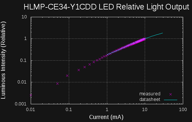
I forgot to post something about the data I was able to collect with the prototype. Here's a plot of the relative intensity of a 5mm LED I've been playing with. The solid cyan line is data I digitized from a plot in the datasheet; the magenta points are data I collected with the system. Where the data is available on the datasheet, there is excellent agreement, but this system can collect data outside the range of the datasheet plots. I only ran the system to about 10 mA max; otherwise, points could be collected up to and beyond the datasheet limits. Of course, if you don't have a datasheet, measuring this data is the only way to get it.

 Ted Yapo
Discussions
Become a Hackaday.io Member
Create an account to leave a comment. Already have an account? Log In.