If I want to analyze the signals/data going over the link cable used by Gameboys, I will need some kind of way to connect a logic analyzer to the link cable. Now the easiest way to do that would probably be to cut a cable in two and solder the wires to some kind of header on a perfboard. However, the "cleaner" way would be to make an adapter. I decided to go with that last option.
When I bought a Gameboy Color a few years a go, my girlfriend also bought one. You can probably guess that it did not take long before I also bought a link cable, so we could battle and trade Pokémon. The cable I bought at the time has an option to plug another cable into it, so you can play with more than 2 players.

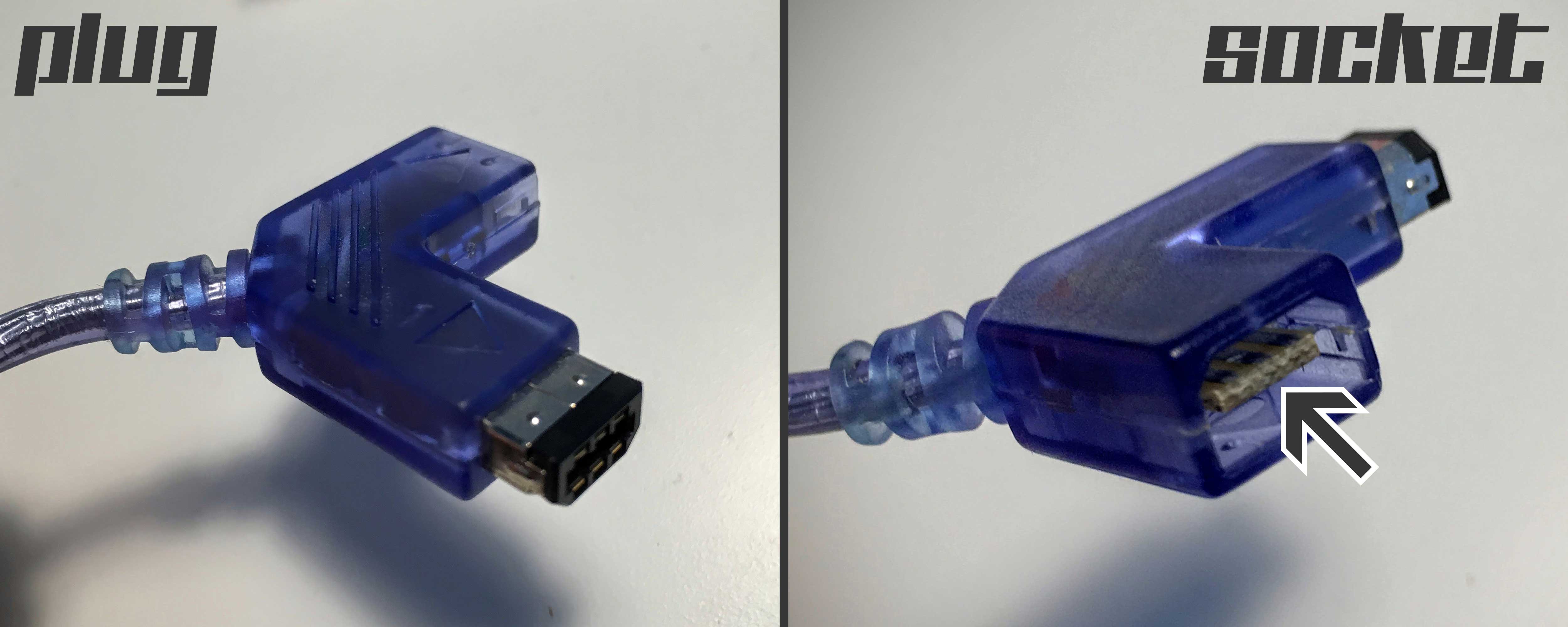
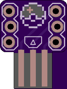
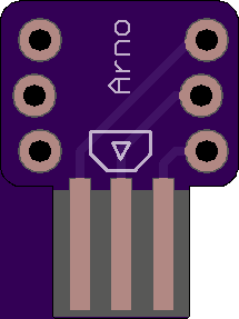
As you can see in the picture, the "socket" on the link cable I have is just a simple PCB with some three pads on each side. The PCB is about 1.2mm thick, but I checked and it looks like the plug will also accept a thicker PCB (1.6mm). I grabbed my caliper and roughly measured the PCB in the socket, as well as the connector that plugs in to it, and designed a part in CadSoft EAGLE. After that I designed a simple breakout board with two 3 pin headers, that should fit just fine on a breadboard. I looked on PCB Shopper, and since I only needed a couple of these boards, OSHPark was the cheapest option for this board.
 |  |
Apparently the combined render on OSHPark has some issues with the outline (the board outline layers looks fine when checked separately). Let's hope the boards come out fine (I'm also curious what the Pokeball looks like in real life).
 Arno Moonen
Discussions
Become a Hackaday.io Member
Create an account to leave a comment. Already have an account? Log In.