Close
0%
0%

ESP8266 Geiger counter

Simple Geiger counter using ESP8266 PWM for HV generation and network connectivity

Similar projects worth following
The ESP8266 is flashed with the MicroPython firmware, and the software PWM is used to drive the HV part of the circuit.
The radiation and dose information will be available via a web interface, MQTT, maybe some lower level output like an UDP or ICMP packet on every particle detection.

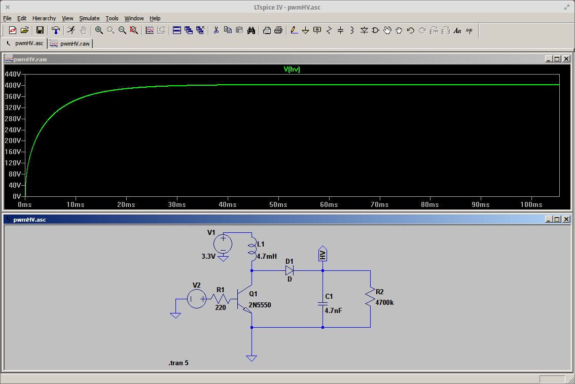
This circuit requires a PWM frequency of about 10kHz or higher, for the HV output not to have a large ripple (See the LTspice simulation in FILES section). A patch for MicroPython (see logs) addresses this issue.

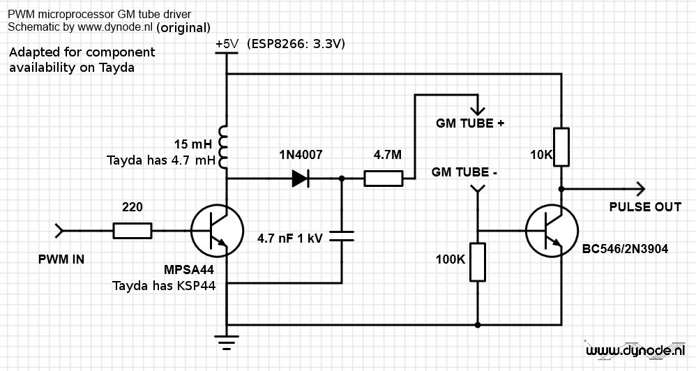
I've adapted the parts for this project given on https://www.dynode.nl/trinket-powered-geiger-counter/ according to availability on Tayda, because I'm trying to keep the total cost of the project around 15 euro. The Geiger tube is the most expensive part, but can be found from Ukraine for under 10 dollar.

I use a WeMos D1 mini for easy programming of the ESP8266.

Code will live in https://github.com/biemster/ESPGeiger. It will be a library that will handle the low level stuff such as PWM and pin assignments, and a general part that will communicate the measurements out to the world.

Since it looks like the PWM duty needs to be calibrated to get the right HV on the tube, the library will have a calibrate function that tries to produce the following plot:
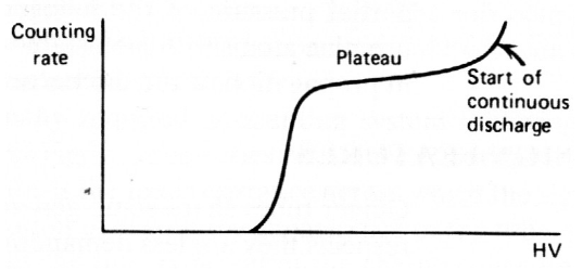
The plateau region is the desired operational region for a Geiger tube. In my case the plot will be the Counting rate as a function of the PWM duty parameter, and not HV as in the example above.

Using this calibration method to determine the duty of the PWM will eliminate the need of special HV testing equipment, since a general multimeter is not able to measure the HV due to the very low current in the circuit (I tried and failed. I could use a gigohm resistor to make a 1000x probe, but I don't have those at the moment. Also, this calibration adds a bit of extra physics to the whole project).

firmware-combined.bin

MicroPython v1.8.3-119-ge4d6a10-dirty on 2016-09-05 with 10kHz PWM

octet-stream - 516.32 kB - 09/05/2016 at 18:42

Download

pwmHV.asc

Net list of the LTspice simulation of the HV part

pgp-encrypted - 1.23 kB - 08/21/2016 at 19:09

Download

  • 1 × ESP8266
  • 1 × STS-5 Geiger tube
  • 1 × 4.7 mH inductor
  • 1 × 4.7 nF 1kV capacitor
  • 1 × KSP44 transistor

View all 12 components

  • Rebuild of circuit on perfboard

    biemster10/01/2016 at 15:45 0 comments

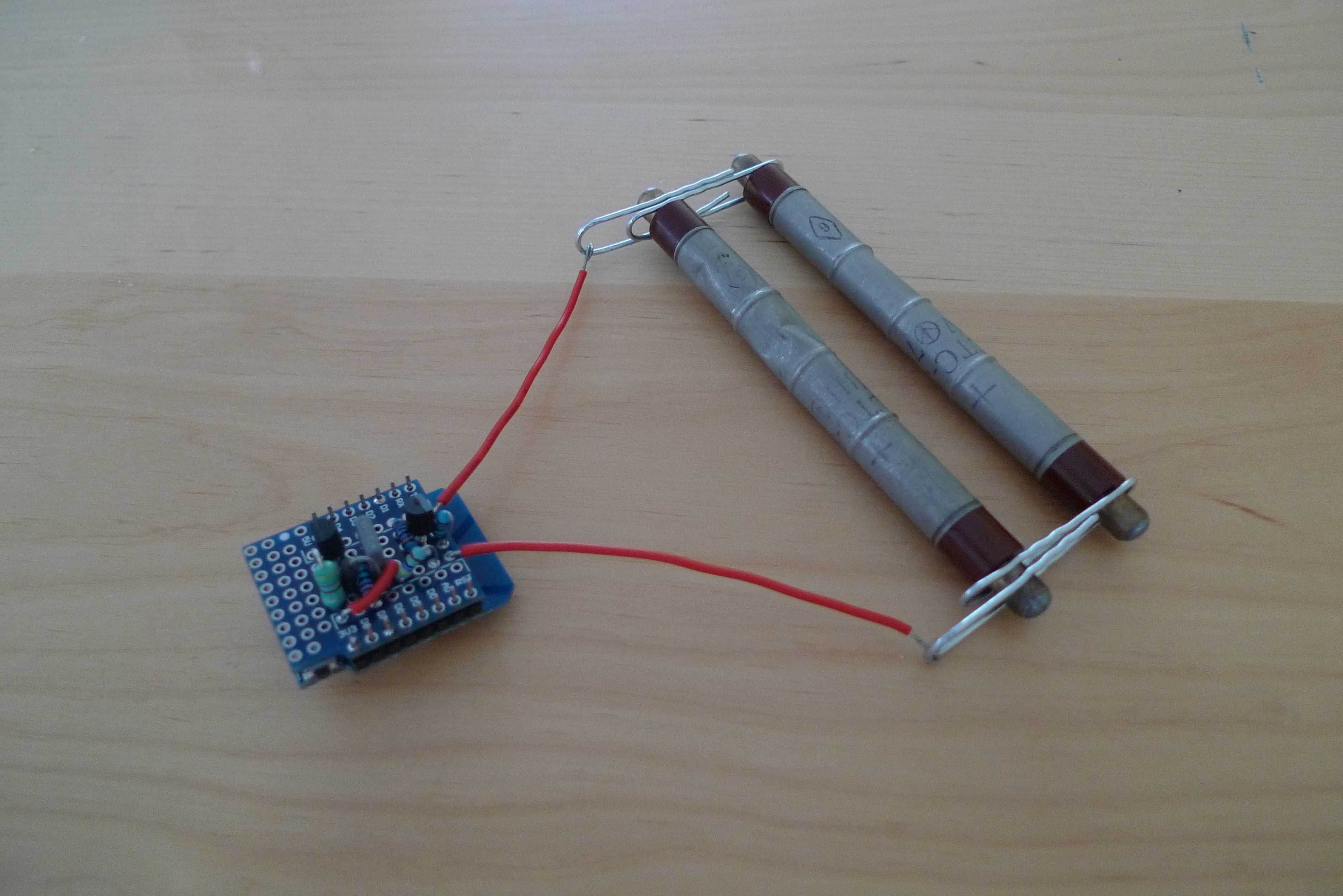
    Last week I received the WeMos protoshields, to solder the components on. The build looks a lot neater now! The ESP8266 is on the bottom, and I omitted the buzzer. I also put both my tubes on a pair of paper clips, to (almost) double the background CPM. I'm getting around 35 +/- 10 now.

    In the mean time I've been working on the python running on the ESP, to get a tiny webpage with a real time feed of the CPM using WebSockets. The initial commit is on github, but not working yet. Next log will be when this is running.

  • Calibration using rain water

    biemster10/01/2016 at 15:32 4 comments

    This will be a short log, rain water apparently is not significantly active (despite other claims). The increase in CPM is about 10-20%, not even close to the 10x as claimed in the first link.

    This might be due to my location close to sea. This natural background comes from radon outgassing from the earth's crust, which might be filtered out by seawater as it bubbles up there. This way the air above sea is much less active as above land, and when the wind comes from the direction of the sea, this inactive air stretches over land a bit. This is just a loose theory of mine though, please comment below if I'm wrong.

    Short story even shorter, calibrating using rain water as a source is not an option for me.

  • Software update: MQTT support

    biemster09/06/2016 at 09:10 0 comments

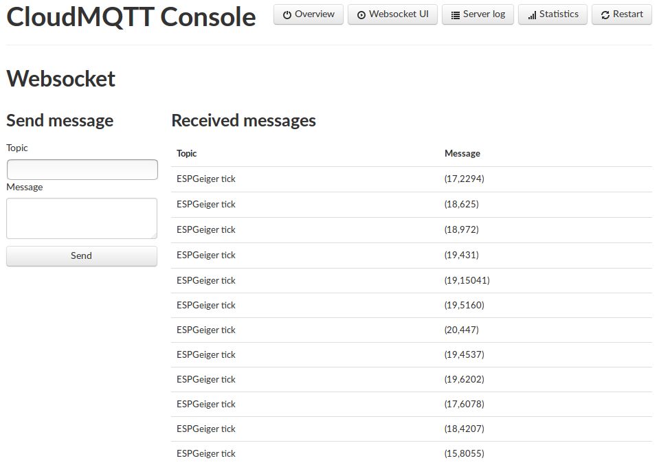
    I've updated the code on github to report every event over MQTT. It also reports the CPM and the time passed since the previous event as (CPM,dt). It uses the uMQTT micropython library, which is very straightforward to use. If you have any suggestions for extra info in the messages, leave a comment below.

    In addition I added a micropython firmware in the FILES section. (version 1.8.3, with 10kHz PWM support)

    The software side of the geiger counter runs quite solid now, I will start focusing on the hardware again. Next step will be moving the circuit to a PCB (I'm thinking a shield for the WeMos, either using the WeMos ProtoShield or go for a custom oshpark/dirtyPCB thing)

    Also I'm still searching for a good source to calibrate the HV (In holland it rains every day, except when you want it to.)

  • SUCCESS! Events are counted, and a beep on every discharge!

    biemster08/31/2016 at 13:28 0 comments

    Yay! With the current version on Github I'm getting nice beeps from background radiation! The calibrate does not give me a plateau I was expecting though:

    >>> geiger.calibrate()
    Calibrating HV in 7 steps of 10 seconds (70s total) from duty=20 to duty=90
    HV pin 13, freq 10kHz, duty 20, event pin 5
    With PWM duty 20 we had 0 counts in 10 seconds
    HV pin 13, freq 10kHz, duty 30, event pin 5
    With PWM duty 30 we had 0 counts in 10 seconds
    HV pin 13, freq 10kHz, duty 40, event pin 5
    With PWM duty 40 we had 3 counts in 10 seconds
    HV pin 13, freq 10kHz, duty 50, event pin 5
    With PWM duty 50 we had 1 counts in 10 seconds
    HV pin 13, freq 10kHz, duty 60, event pin 5
    With PWM duty 60 we had 5 counts in 10 seconds
    HV pin 13, freq 10kHz, duty 70, event pin 5
    With PWM duty 70 we had 4 counts in 10 seconds
    HV pin 13, freq 10kHz, duty 80, event pin 5
    With PWM duty 80 we had 5 counts in 10 seconds
    >>> 
    
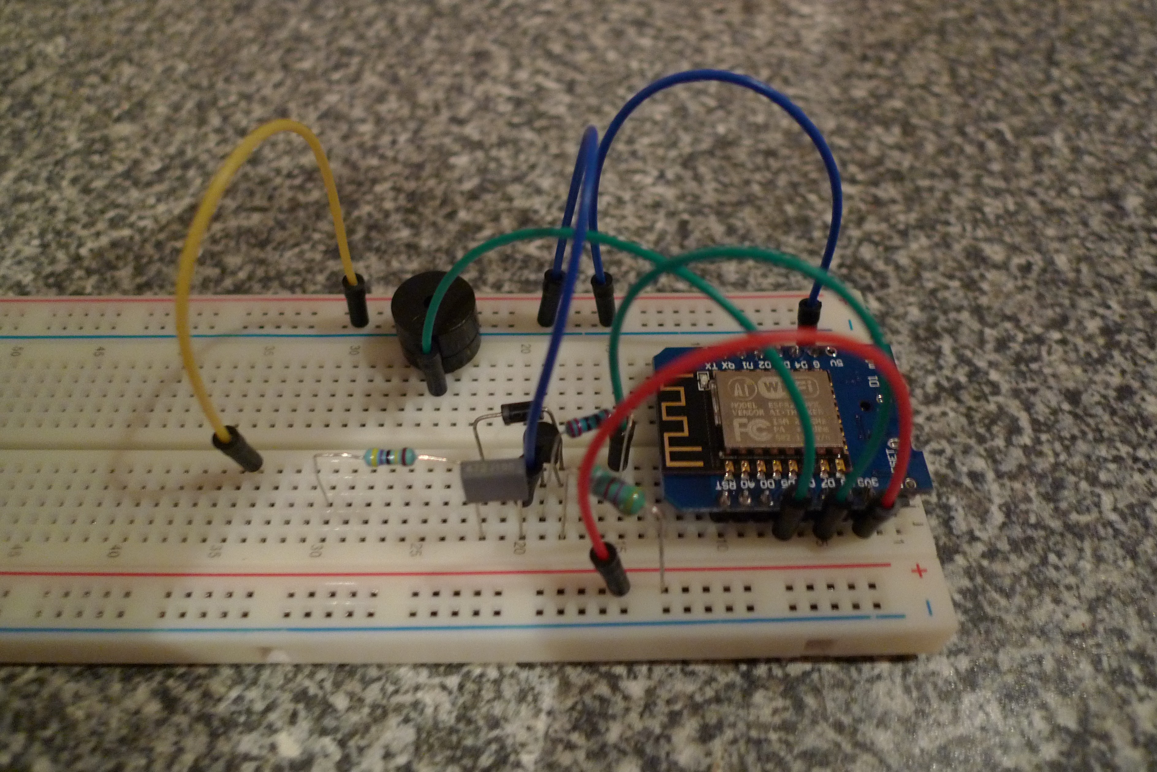
    So apparently I'm not able to get the tube in continuous discharge mode. This might as well be a limitation of the HV part of the circuit though. Later today I'll post a nice picture in this log of the whole thing on the breadboard, and the next step is to try to calibrate it using a radioactive source. (I've heard that fresh rain is an OK source).

  • Interrupt handler

    biemster08/30/2016 at 17:55 0 comments

    Today I built the whole circuit on the breadboard, attached the tube and played a bit with the PWM duty to see if it registers something. The circuit keeps the D1 pin of the ESP high, and pulls it to ground if the tube discharges. This is the code that I hoped would then record the event:

    from machine import Pin, PWM
    
    cumulative_count = 0
    
    def init(...):
        ...
        # geiger discharge irq handler (pin5=D1)
        discharge = Pin(event_pin, Pin.IN)
        discharge.irq(trigger=Pin.IRQ_FALLING, handler=geiger_discharge_handler)
    
    ...
    
    def geiger_discharge_handler():
        # this handler is called everytime the tube discharges
        cumulative_count += 1
        buzz()
    
    def buzz()
        ...
    However, it seems not as easy as I thought it was (although I tried to follow the official MicroPython for ESP8266 docs).

    When this runs with a PWM duty of 60%, I start getting this in the REPL at random intervals on average every 2 seconds:

    NameError:
    NameError:
    Just this error twice, without any error message. (Well wait, now I think of it the timing of the intervals of this error message is about the same as what I would expect from background radiation detection in the tube, can it be that the rest of the built actually works??).

    If I put a print in the handler

    print('click!')
    I get the following error, at the same random intervals:
    TypeError:
    Again no error message. I'll have to dive into the restrictions of the IRQ handlers a bit more to see what I'm doing wrong.

    But on a side note, everything else seems to work! The handler is called at random intervals, consistent with the tube registering background radiation! Now to figure out how to write a proper handler that actually does something else than throwing an error. Expect the next log titled "SUCCESS!" and with some pictures of a working GM counter soon!

    Update:

    I found this paragraph in the docs. It explains why I don't see an error report on the throws (simply because the ISR is not able to like this).

    Adding the following lines to the code should enable error reporting in the ISR:

    import micropython
    micropython.alloc_emergency_exception_buf(100)

    Also, it seems that I should not call a function inside my ISR, and the global variable 'cumulative_count' should be defined

    global cumulative_count

    in the ISR. Let's see if those changes improve the situation

    Update2:

    micropython.alloc_emergency_exception_buf(100)

    is not implemented on my version so I guess i need to recompile. Also, the ISR needed to accept a parameter:

    def geiger_discharge_handler(p):

    now with the global cumulative_count, this variable is increased on every count! Good progress, I only need to figure out how to call a function from the ISR so I can beep the buzzer, and start doing MQTT etc stuff. At the moment when I call the buzz() function I get a

    MemoryError:

  • Using the ADC to calibrate the HV

    biemster08/27/2016 at 20:17 8 comments

    It occurred to me to use the ESP's ADC to tune the PWM duty such that there is the correct 400V on the tube.

    The ADC of the ESP has a tolerance between 0 and 1 Volt. To measure the HV without overloading the ADC port I have to create a voltage divider that has let's say 0.400 Volt on the ADC corresponding to 400V over the tube.

    I know from previous measurements of the HV part of the circuit that I need a load of around 100 megohm or larger for the output to reach the desired 400V. So I could take a 100 megohm and 100kOhm in the voltage divider, to divide the HV by about a factor 1000.

    Now that's where the problem begins. A second resistance of 100k in the voltage divider will probably not be more than an order of magnitude smaller than the internal resistance of the ADC, so this will alter the behavior of the voltage divider. Now since this second part of the voltage divider depends on the internal resistance of the ADC, I could use just this internal resistance as second stage, lose the 100k altogether.

    But the important question still remains:

    What is the internal resistance of the ADC?

    Info on the ADC of the ESP8266 is scarce to say the least. I've seen reports on forums mentioning 1M, but it apparently also depends on how often the ADC port is polled.

    Seriously, if anybody can shed some light on the internal resistance of the ADC, or some other way to measure 400V with it but at the same time burning extremely low current, please comment below. Any hints or thoughts are welcome.

  • HV part on breadboard

    biemster08/26/2016 at 20:17 2 comments

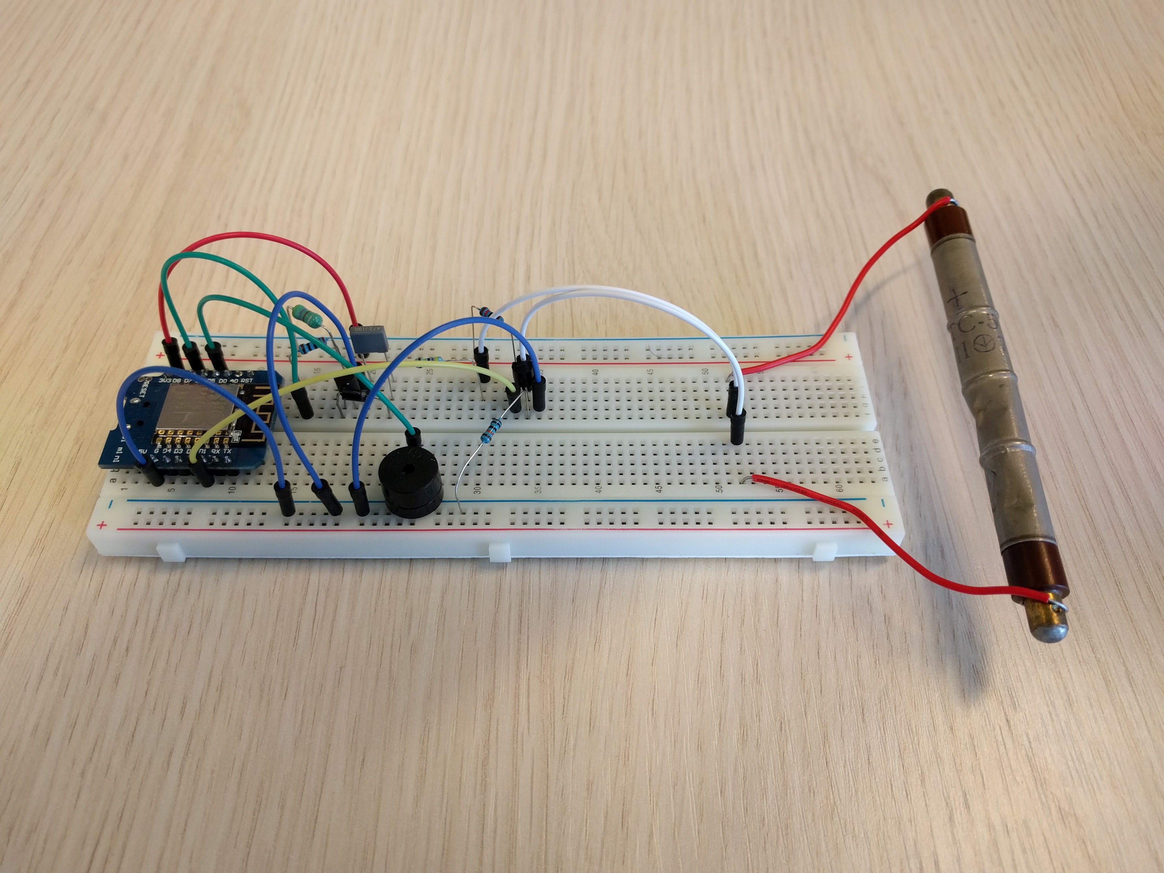
    I've built the HV part on a breadboard, and with the main.py and ESPGeiger.py as committed to github it appears to work as expected. The circuit gives a very nice and faint high pitch beep if I listen very closely.

    When I try to measure the HV directly with my multimeter (which has an internal resistance of 1M), I get a reading of a couple of Volts. This is due to the low current in the circuit. If I measure via the 4.7M resistor as a voltage divider, I get a readout close to 30 Volts. This indicates that the voltage at the HV point is indeed pulled down by the DM. Unfortunately at the moment I don't have a gigohm resistor to build a large enough voltage divider, or a 1000x probe to measure the HV correctly.

    I'm going to assume that the setup like this is indeed capable of generating the necessary 400V, as is shown in the links from the LINKS section in this project.

    Next step is to put the rest of the circuit (2 resistors and one transistor) on the breadboard, and run the ESPGeiger.calibrate() routine to find the Geiger plateau as a function of PWM duty.

  • Code on github

    biemster08/26/2016 at 14:26 0 comments

    I've started coding the python that needs to run on the ESP to drive the hardware part. It requires the PWM for the HV, and an interrupt handler to listen for and act on discharges in the tube.

    It will live on github.

    It features a calibrate routine, which will try to produce the plot as described in the details section of this project. This eliminates the need for HV measurement equipment, but still enables the end user to set the correct PWM duty for the correct HV required by the geiger tube.

    I'm using mpfshell to upload the two scripts to my ESP.

  • MicroPython 10kHz soft PWM

    biemster08/22/2016 at 19:42 0 comments

    The original MicroPython allows for a soft PWM with a maximum frequency of 1 kHz. Simulation with LTspice and the provided net list shows that there is a significant ripple on the HV output on this frequency. With a PWM frequency of 10 kHz this ripple is almost not present.

    To allow a 10 kHz PWM signal from the ESP8266 the following small changes to esp8266/esppwm.c are necessary:

    diff --git a/esp8266/esppwm.c b/esp8266/esppwm.c
    index f1d7060..e8c787b 100644
    --- a/esp8266/esppwm.c
    +++ b/esp8266/esppwm.c
    @@ -25,8 +25,8 @@
     #define ICACHE_RAM_ATTR // __attribute__((section(".text")))
     
     #define PWM_CHANNEL 8
    -#define PWM_DEPTH 1023
    -#define PWM_FREQ_MAX 1000
    +#define PWM_DEPTH 100
    +#define PWM_FREQ_MAX 10000
     #define PWM_1S 1000000
     
     struct pwm_single_param {

    You could choose any values you'd like, as long as the product of PWM_DEPTH and PWM_FREQ_MAX does not exceed PWM_1S. I've tested it with a logic analyzer and it seems to work fine.

  • LTspice simulation of HV part

    biemster08/21/2016 at 19:25 6 comments

    The net file pwmHV.asc can be found in the FILES section of the project.

    The circuit seems to reach the operating voltage of the tube of ~400V after about 15 ms. I used a PWM duty of 66% at V2 in this run. The plateau voltage is however highly dependent on the resistor at R2, which I took to be the anode resistor.

    My main purpose for this simulation was to check if the lower input voltage of 3.3V and the lower inductance of 4.7 mH could still generate enough HV for the tube, and it seems that it can. So next step is to put it on a breadboard, and start searching for the Geiger plateau.

View all 11 project logs

Enjoy this project?

Share

Discussions

Tony wrote 06/20/2019 at 17:13 point

ok thank you.

  Are you sure? yes | no

Tony wrote 05/27/2019 at 19:51 point

How easy would this be to add a display to the circuit?

  Are you sure? yes | no

biemster wrote 06/20/2019 at 12:47 point

Sorry for the delayed reply, I don't seem to get notifications anywhere when somebody adds to the discussion..

It would be very easy to add a display, the ESP8266 and micropython have numerous libraries and turn key solutions for that.

  Are you sure? yes | no

Similar Projects

Does this project spark your interest?

Become a member to follow this project and never miss any updates