 Uriel Katz
I read quite a bit in order to get this right. First I needed to understand how a RAMPS 1.4 board is typically connected - that information can be found here.
Next I needed to map the connectors in the mightyboard (My bot uses Rev-H):
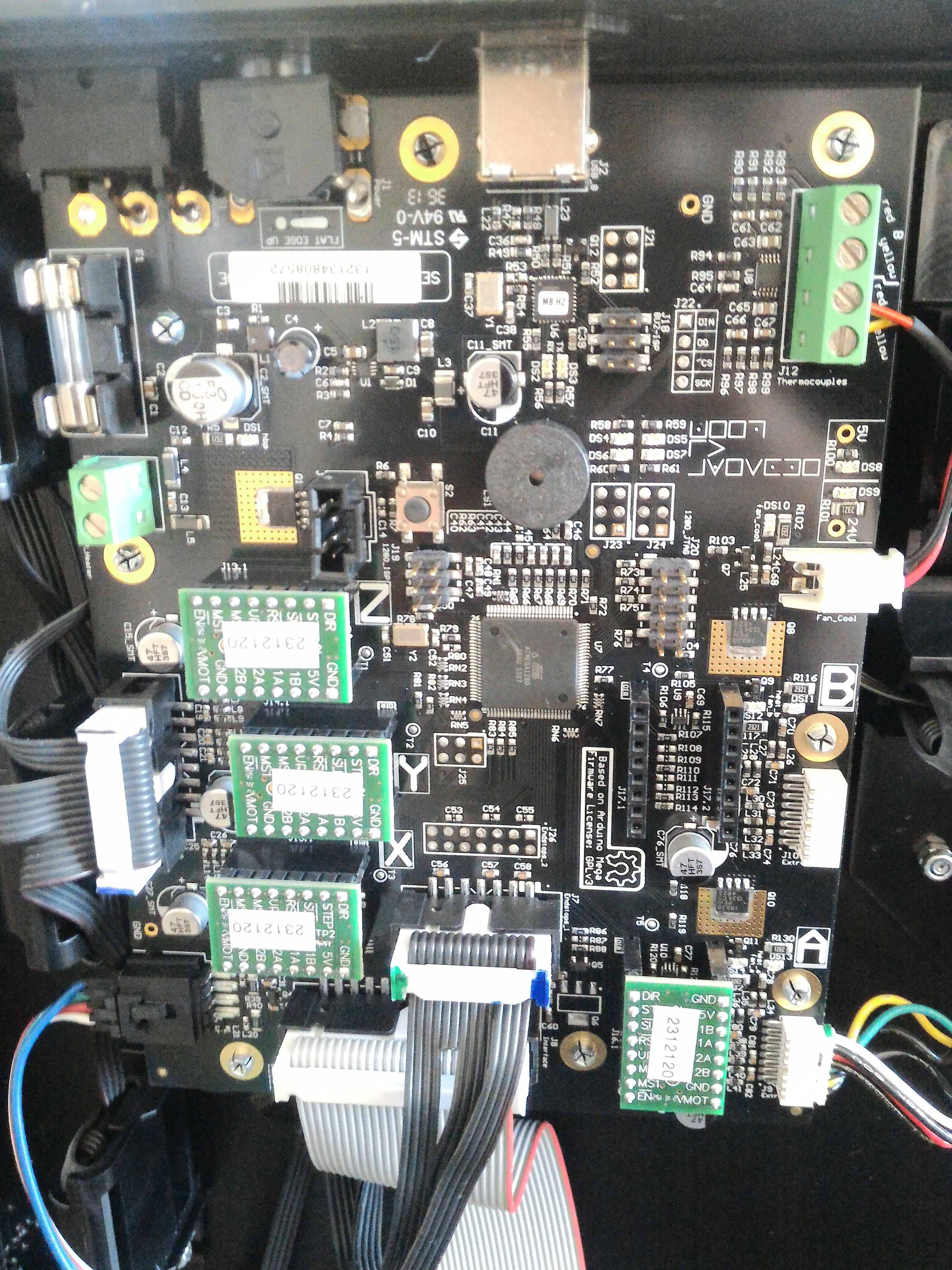
- Bottom Left - LED strip, this one is not used for no so I haven't mapped it
- Above that - Steppers connector, it looks like this:|———/\————|| 2 1 N 2 1 N 2 1 | A| 2 1 N 2 1 N 2 1 | B|———--————|
Where 2/1 is coil number and A/B is wire of the coil per RAMPS 1.4 convention.
The order of stepper motors (from left to right) is X,Y,X - Bottom middle - LCD screen, not used since I use Reprapdiscount LCD controller
- Above that - endstops connectors, the Replicator 2 has only min endstops, the pins are:|———/\—————|| S G S G N S G || G V G V N G V ||———--—————|Where S is Signal, G is Ground, V is VCCEndstops from left to right:X, Y, Z
- Bottom right - Extruder: stepper+fan+heating element - the pins are:|——\__/——————————————|| HP HN FP FN 2B 2A 1B 1A ||——————————————————|
Where:
HP/HN - Heater positive/negative
FP/FN - Fan positive/negative - Middle right - active cooling fan, not using it for now to keep things simple
- Top right - thermocouple, not used, using a Thermistor
In the end the connectors that I need were: steppers, endstops, extruder
Discussions
Become a Hackaday.io Member
Create an account to leave a comment. Already have an account? Log In.