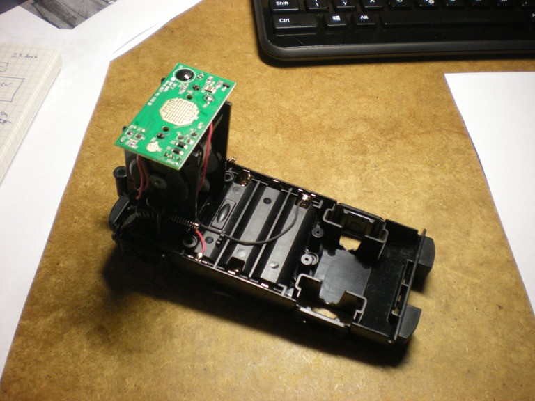
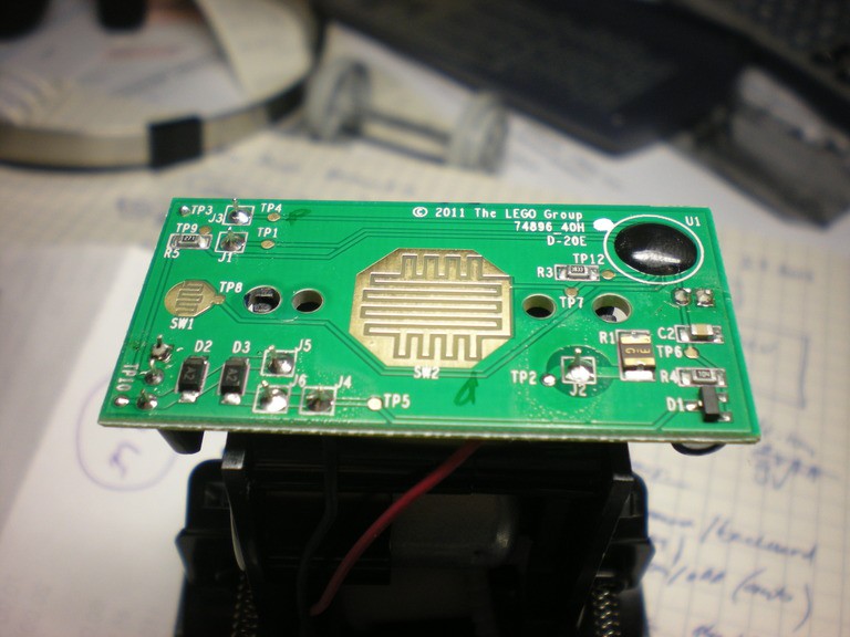
There are two ways to determine the current passing through the motor. I can measure it, which requires de-soldering the wires to the motor, or I can determine what components are used in the original circuit and trust the designer that the parts are well sized.

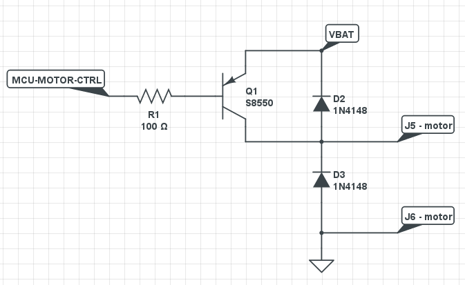
I've started with the latter and found out that the motor is controlled by a single PNP transistor S8550.
 This is the motor driver circuit.
 Since the locomotive goes only in one direction a single transistor is sufficient. The positive battery terminal is not 100% correct, it is wired through a resistor R1, but I'm not sure about its use or value (also note that the R1 label in the schematics should be R5).
 Simon Fojtu
Discussions
Become a Hackaday.io Member
Create an account to leave a comment. Already have an account? Log In.