AngelLM
-
Thor at Bilbao Maker Faire!
11/21/2016 at 16:11 • 1 commentThis weekend I was at Bilbao Maker Faire showing Thor. The event was great and I met a lot of interesting people.
I met Antonio, the creator of DIMER, who was located next to me at the faire, so we managed to interact our robotic arms with each other... And here is the result! (Maybe the first marriage proposal between robotic arms?)
As you can see in the video, Thor is moving faster than weeks ago. I increased the speed of the slowest articulations about 50%. Soon i'll test the maximum speeds that Thor can support.
Another great new is that I have been using Thor for 8h non-stop working and it didn't broke or melt neither! Yay!
Next things I'll be working on: Test the maximum speeds, making a conveyor belt that will interact with Thor, design a new electronic board and add a new degree of freedom (hehe >:D).
Finally, I just saw the awesome work of Danny... Just go to his project page and see it with your own eyes...Best regards!
-
Overheating problem fixed!
11/07/2016 at 21:12 • 0 commentsHi everyone!
First of all, thank you for your 100 likes 276 followers & over of 15k views. You rock!
We have another thing to celebrate today hehe. The problem about melting gears and malfunction due to steppers overheating is solved :) Let me explain the steps I followed to fix it.
1. I measured the temperature of steppers in action... and it went over 70ºC. PLA starts deforming at 60ºC... So I had a real problem there. Not only the gears were deforming, also the Art1Body part were deforming and causing the malfunction.
2. I appreciated that my design didn't had refrigeration holes, so the heat produced by the steppers only could be dissipated through the plastic (bad idea because it was causing the deformation). After facepalming myself I redesigned the parts that contain steppers and introducing 40mm fans into the design. In this way, the motors would have forced cooling.
3. I tested it. And it worked well, now the steppers don't reach 40ºC and it goes well! Just in case I printed the gears using ABS to prevent the deformation. The test was performed at a 10h non-stop maker faire called OSHWDEM at A Coruña (Spain).
So, check the new design at GitHub repo before print it! And if you have printed it already don't worry. Take the dremel, do some holes and glue the fans! (I did this hahaha)
Aaaand... there you have a video of Thor doing a manipulation job. I think that the next step is increase its speed, don't you?
-
Beeing part of this project
10/10/2016 at 12:12 • 0 commentsHi everyone!
I have received some applications from Hackaday users that wanted to be part of this project. And I think that it's important to explain how to be part of this project.
In one hand, this project is completely Open Source and shared on its GitHub's repository. This mean that you can share your modifications and beeing part of this project by doing pull requests, giving feedback or helping solving issues.
In the other hand, there is the "Project Team" on Hackaday. I don't really want (and I think no one wants) to have a Team with a lot of inactive users. I think that this Team is a nice place to share opinions, test designs, test features and things like that. Obviously, the team has the labour to gather all this information and make it public too!
In this way, everyone could access to all the info and the Team members would have a place to share their progress.And the final question: How to be a Team Member? I think the best solution is accepting the requests of the users that contribute. So, if you want to join this Team, I suggest you to go to the GitHub repository, clone it, make something nice and send a pull request!
What do you think about this?
¡Regards!
-
Inverse Kinematics
08/18/2016 at 18:44 • 3 commentsToday I'll share the solution of the Thor's Inverse Kinematics.Inverse Kinematics (IK) allows to find the robot's joint parameters (q1, q2, q3, q4, q5, q6) that do robot's tip to position according to a specific spatial location (p,[n,o,a]).
To do the Thor's IK calculus I have used the kinematic decoupling procedure. This procedure allows to calculate, the joint parameters (q1, q2, q3) that place the robot's tip in a point of the space first and then calculate the joint parameters (q4, q5, q6) responsible for the wrist's position and orientation.
Geometric method: q1, q2, q3
We have to bear in mind that the point that the IK will position won't be the Tool Center Point (TCP) but the 5th joint axis' center (Pm). Therefore, given an orientation and position of the TCP (noap_tcp) and because the 4th, 5th and 6th joints cross in a single point and the TCP's Z axis crosses Pm, then:
![]()
Geometrically we obtain the following equations:
where:
Rotation matrices: q4, q5, q6
Thanks to the forward kinematics the Pm's position and orientation due to q1, q2 and 13 can be obtained. As the position is no longer needed, it can be possible to operate only with the R:
Which is the same as:
I have used the SymPy tool (mentioned on the Forward Kinematics log) to do the symbolic calculus. The results are the following:
Hope you like it!
-
Thor's new brain received!
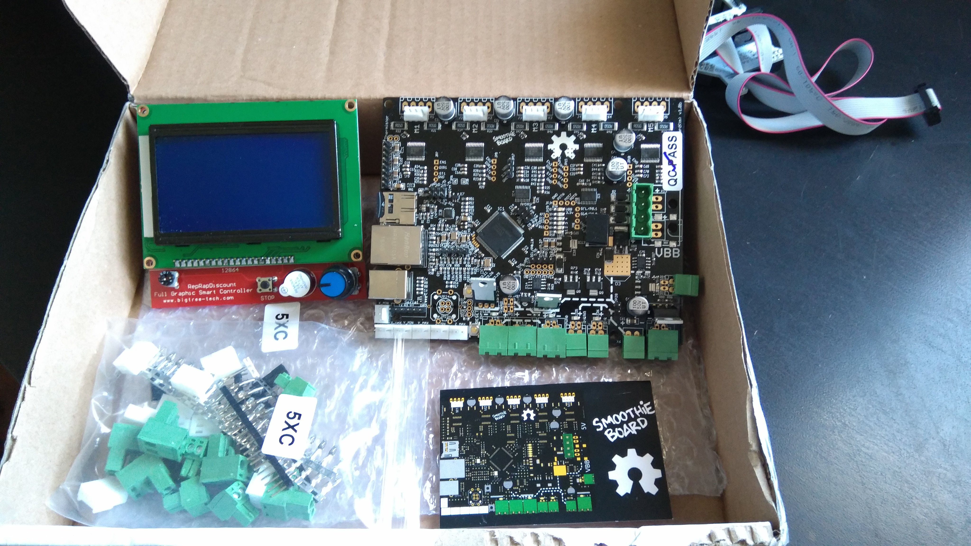
08/18/2016 at 16:20 • 0 commentsAs I said, Arthur Wolf from SmoothieWare sent me a SmoothieBoard to test it in Thor.
And I just received it!
![]() It seems pretty awesome and they have included a LCD Screen in the package! Yay!
It seems pretty awesome and they have included a LCD Screen in the package! Yay!
The board can control up to 5 steppers, so I'll need to add another driver in order to control one more.Next steps will be:
- Study the board
- Study the firmware
- Test the board with the standard firmware
- Modify the firmware to adapt it to Thor
- Add an additional driver
- Test it all with Thor
Regards!
-
Forward Kinematics
08/17/2016 at 17:34 • 0 commentsToday I'll share Thor's Forward Kinematics calculus.
Forward kinematics allows to compute the position of the end-effector from specified values for the joint parameters.
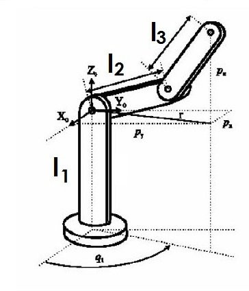
In order to resolve the Forward Kinematics I have used the Denavit-Hartenberg parameters.
![]()
Link θ d a α 1 q1 L1 0 90 2 q2-90 0 L2 0 3 q3 0 0 90 4 q4 L3 0 -90 5 q5 0 0 90 6 q6 0 0 0 After obtaining the previous data, we have to calculate the transformation matrices:
Replacing with our data:
In order to obtain the transformation matrix (T) between the base and the end of the robot we have to multiply the previous matrices as shown:
The resulting T matrix is formed by a 3x3 sub-matrix destined to orientation (n,o,a) and by a 3x1 vector destined to position (p).
As the calculus of this transformation matrix is not trivial, I have used the OpenSource tool SymPy to do the symbolic operations (code available below).
The SymPy code used:
C1 = Symbol('C1')

C2 = Symbol('C2')

C3 = Symbol('C3')

C4 = Symbol('C4')

C5 = Symbol('C5')

C6 = Symbol('C6')

S1 = Symbol('S1')

S2 = Symbol('S2')

S3 = Symbol('S3')

S4 = Symbol('S4')

S5 = Symbol('S5')

S6 = Symbol('S6')

L1 = Symbol('L1')

L2 = Symbol('L2')

L3 = Symbol('L3')

L4 = Symbol('L4')

A1=Matrix([[C1,0,S1,0],[S1,0,-C1,0],[0,1,0,L1],[0,0,0,1]])

A2=Matrix([[S2,C2,0,L2*S2],[-C2,S2,0,-L2*C2],[0,0,1,0],[0,0,0,1]])

A3=Matrix([[C3,0,S3,0],[S3,0,-C3,0],[0,1,0,0],[0,0,0,1]])

A4=Matrix([[C4,0,-S4,0],[S4,0,C4,0],[0,-1,0,L3],[0,0,0,1]])

A5=Matrix([[C5,0,S5,0],[S5,0,-C5,0],[0,1,0,0],[0,0,0,1]])

A6=Matrix([[C6,-S6,0,0],[S6,C6,0,0],[0,0,1,L4],[0,0,0,1]])

A1*A2*A3*A4*A5*A6
Hope you like it!
-
Thank you & some good news!
08/10/2016 at 16:34 • 0 commentsFirst of all, thank you everyone who has seen this project. More than 1000 views in a week, awesome!
Good news: Arthur Wolf from SmoothieWare contacted me to send me a new brain for Thor... A SmoothieBoard!. This board could be the best substitute for my DIY control board as it's OpenSource too. Can't wait to receive it! I'll keep you up to date ;)
I just finished the video of the assembly. I know that the more details the better, that's why I'll update the assembly instructions with the steps to visualize it on FreeCAD.
Finally, I'm currently working on the kinematics of Thor, I'll make another log with the Forward & Inverse Kinematics and how I solved it.
Regards!