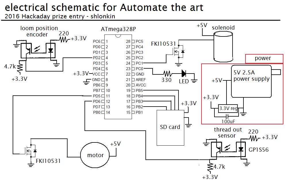
The electronics are not so complicated. I'll let you look over the schematic before I try to explain.

Notes:
- I would prefer everything to use the 5V rail for simplicity, but that pesky SD card won't let me.
- The encoder and end of thread sensor are photointerruptors I pulled out of my parts bin.
- The motor is a high torque/low speed one salvaged from a printer.
- I haven't received the solenoid yet, but it's rated 12V, 2A, 10mm travel, 20N pull force. I don't need much force so I'm hoping 5V will be enough.
- The LED is for status signals such as errors, finished, I'm hungry.
Oh-crap-the-thread-ran-out sensor -
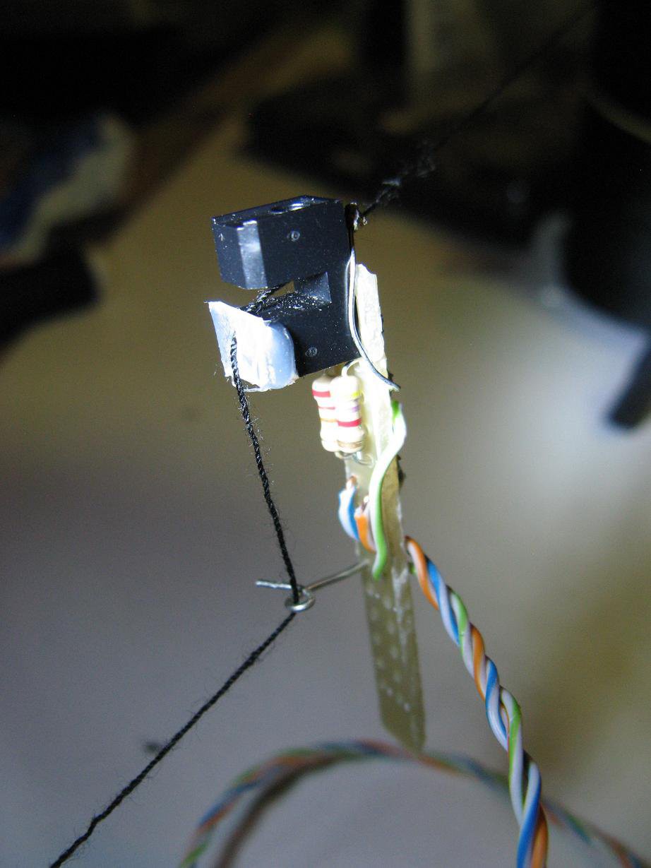
This was a considerable challenge that seemed so easy in my mind, but was not so. I toyed with mechanical devices such as light springs held by the thread, or contacts held apart by thread. But thread is so thin and flexible that I swiftly abandoned that idea and looked for something optical. Digging through my parts bin I found a photointerruptor that just happened to have a little groove the size of my thread right in front of the LED and a hole in the center of the base. It was perfect. The thread runs through the hole in the base, directly between the LED and detector, guided by the groove, and over to a wire loop guide. Here's a picture, but it's hard to see exactly what's going on. The white piece of plastic glued on the device is just to ensure the thread stays in line.
It works great. With thread in place I read a full 5V (on a 5V supply), but when the thread is pulled out it drops to 1.6V which is good enough. When the voltage drops the controller will pause everything and flash a signal on the LED. I'm thinking of adding a button that will let the program resume, but it's not quite as simple as that.
If you want to see where that thread goes from here, wait for the upcoming log that will cover the thread route and tensioner.
 shlonkin
Discussions
Become a Hackaday.io Member
Create an account to leave a comment. Already have an account? Log In.