 Ianislav Trendafilov
Today I was able to communicate with a simple I2C slave that I have created for proof-of-concept. What you need (step-by-step instructions):
1. Enable i2c-gpio in kernel
2. Compile and load i2c-gpio-param kernel module from https://github.com/kadamski/i2c-gpio-param
3. Create a Parallel IO bus in FPGA using Qsys . Pin type should be BiDirectional
4. Compile and upload your new RBF. Then load using device-tree overlay as it was described in older project logs here.
5. Create a new overlay and load it on top of other one. In my case (as a diff from Quartus output):
/dts-v1/;
/ {
        fragment@0 {
                target-path = "/clocks";
                #address-cells = <1>;
                #size-cells = <1>;

                clk_0: clk_0 {};
        };

        fragment@1 {
                target-path = "/sopc@0";
                #address-cells = <2>;
                #size-cells = <1>;

                fpga_mgr0: fpga_mgr@ff706000 {};
                base_fpga_region: base_fpga_region@0xff200000 {};
                hps_0_arm_gic_0: intc@0xfffed000 {};
        };

        fragment@2 {
                #address-cells = <2>;
                #size-cells = <1>;
                target-path = "/sopc@0/bridge@0xc0000000";
                __overlay__ {
                        #address-cells = <2>;
                        #size-cells = <1>;
                        ranges =
                                <0x00000000 0x00000000 0xc0000000 0x00010000>,
                                <0x00000001 0x00020000 0xff220000 0x00000008>,
                                <0x00000001 0x00010000 0xff210000 0x00000008>,
                                <0x00000001 0x00010008 0xff210008 0x00000008>,
                                <0x00000001 0x00010080 0xff210080 0x00000010>,
                                <0x00000001 0x000100c0 0xff2100c0 0x00000010>,
                                <0x00000001 0x00010040 0xff210040 0x00000020>;

                        gpio1h_pio: gpio@0x100010040 {
                                compatible = "altr,pio-16.0", "altr,pio-1.0";
                                reg = <0x00000001 0x00010040 0x00000020>;
                                interrupt-parent = <&hps_0_arm_gic_0>;
                                interrupts = <0 42 1>;
                                clocks = <&clk_0>;
                                altr,gpio-bank-width = <4>;     /* embeddedsw.dts.params.altr,gpio-bank-width type NUMBER */
                                altr,interrupt-type = <3>;      /* embeddedsw.dts.params.altr,interrupt-type type NUMBER */
                                altr,interrupt_type = <3>;      /* embeddedsw.dts.params.altr,interrupt_type type NUMBER */
                                edge_type = <2>;        /* embeddedsw.dts.params.edge_type type NUMBER */
                                level_trigger = <0>;    /* embeddedsw.dts.params.level_trigger type NUMBER */
                                resetvalue = <0>;       /* embeddedsw.dts.params.resetvalue type NUMBER */
                                #gpio-cells = <2>;
                                gpio-controller;
                        }; //end gpio@0x100010040 (gpio1h_pio)
                };
        };
};
6. (optional) You can validate it actually works by using gpio bit-banging with: this script#!/bin/sh
DIPSW_COUNT=4
DIPSW_BASE=363
DIPSW_END=$((${DIPSW_BASE} + ${DIPSW_COUNT} - 1))
BTNSW_COUNT=2
BTNSW_BASE=331
BTNSW_END=$((${BTNSW_BASE} + ${BTNSW_COUNT} - 1))
LED_COUNT=8
LED_BASE=395
LED_END=$((${LED_BASE} + ${LED_COUNT} - 1))
function load_rbf {
if [ ! -d /config/device-tree/overlays/load_rbf ]
then
echo "Mounting configfs"
mkdir -p /config
mount -t configfs configfs /config
mkdir /config/device-tree/overlays/load_rbf
sleep 1
echo "Load RBF binary"
# cat /root/load_rbf_only.dtbo > /config/device-tree/overlays/load_rbf/dtbo
cat /root/load_3dtof.dtbo > /config/device-tree/overlays/load_rbf/dtbo
fi
}
function gpio_enable {
if [ ! -d /sys/class/gpio/gpio$1 ]
then
echo "Enabling GPIO $1"
echo $1 > /sys/class/gpio/export
fi
}
function gpio_direction {
gpio_enable $1
if [ "x$2" != "x$(cat /sys/class/gpio/gpio$1/direction)" ]
then
echo "Enable GPIO $1 as ${2}put"
echo $2 > /sys/class/gpio/gpio$1/direction
fi
}
function gpio_in {
gpio_direction $i "in"
}
function gpio_out {
gpio_direction $i "out"
}
load_rbf
for i in $(seq ${DIPSW_BASE} ${DIPSW_END})
do
gpio_in $i
done;
for i in $(seq ${BTNSW_BASE} ${BTNSW_END})
do
gpio_in $i
done;
for i in $(seq ${LED_BASE} ${LED_END})
do
gpio_out $i
done;
7. Add a new i2c device with command:
# 2 = bus id
# 333 = GPIO1[34] , 335 = GPIO1[35]
# 500 = 500usec delay or equal to 2kHz
# 1000 = 1ms timeout
# 0 0 0 = non open drain
echo 2 333 334 500 1000 0 0 0 > /sys/class/i2c-gpio/add_bus
8. Connect an I2C Slave device. I have used a MSP430F5529LP board and created that code (modifying TI examples):#include "driverlib.h"
#define SLAVE_ADDRESS 0x3F
uint8_t transmitData;
void main(void) {
WDT_A_hold(WDT_A_BASE); // Disable watchdog
//Assign I2C pins to USCI_B0
GPIO_setAsPeripheralModuleFunctionInputPin(
GPIO_PORT_P4,
GPIO_PIN1 + GPIO_PIN2);
//Initialize I2C as a slave device
USCI_B_I2C_initSlave(USCI_B1_BASE, SLAVE_ADDRESS);
//Enable I2C Module to start operations
USCI_B_I2C_enable(USCI_B1_BASE);
//Set in transmit mode
USCI_B_I2C_setMode(USCI_B1_BASE,
USCI_B_I2C_TRANSMIT_MODE);
//Initialize transmit data buffer
transmitData = 0xAB;
while (1) {
// Poll for start
while (0x00 == USCI_B_I2C_getInterruptStatus(USCI_B1_BASE,
USCI_B_I2C_START_INTERRUPT)) {
;
}
// Poll for transmit flag
while (0x00 == USCI_B_I2C_getInterruptStatus(USCI_B1_BASE,
USCI_B_I2C_TRANSMIT_INTERRUPT)) {
;
}
//Transmit data
USCI_B_I2C_slavePutData(USCI_B1_BASE, transmitData);
// Increment TXData
//transmitData++; // disable to validate transmission line for errors :)
// Poll will STOP is received
while (0x00 == USCI_B_I2C_getInterruptStatus(USCI_B1_BASE,
USCI_B_I2C_STOP_INTERRUPT)) {
;
}
}
}
9. You should add pull-up resistors to the bus like http://quick2wire.com/wp-content/uploads/2012/05/image00.png (I'm too lazy to create a schematic for that)
10. Test with:
# i2cget 2 0x3F
WARNING! This program can confuse your I2C bus, cause data loss and worse!
I will read from device file /dev/i2c-2, chip address 0x48, current data
address, using read byte.
Continue? [Y/n]
0xab
11. You can look for your device on the bus with:
# i2cdetect 2
WARNING! This program can confuse your I2C bus, cause data loss and worse!
I will probe file /dev/i2c-2.
I will probe address range 0x03-0x77.
Continue? [Y/n]
     0  1  2  3  4  5  6  7  8  9  a  b  c  d  e  f
00:          -- -- -- -- -- -- -- -- -- -- -- -- --
10: -- -- -- -- -- -- -- -- -- -- -- -- -- -- -- --
20: -- -- -- -- -- -- -- -- -- -- -- -- -- -- -- --
30: -- -- -- -- -- -- -- -- -- -- -- -- -- -- -- 3f
40: -- -- -- -- -- -- -- -- -- -- -- -- -- -- -- --
50: -- -- -- -- -- -- -- -- -- -- -- -- -- -- -- --
60: -- -- -- -- -- -- -- -- -- -- -- -- -- -- -- --
70: -- -- -- -- -- -- -- --
I will create a GitHub repo in the future with all that code
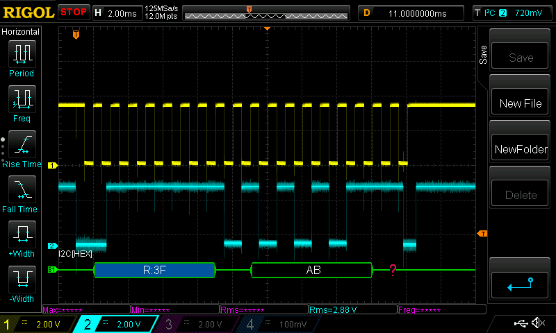
Results on data bus:
Discussions
Become a Hackaday.io Member
Create an account to leave a comment. Already have an account? Log In.