 agp.cooper
I2C Master-Slave using the DigiSpark
Start looking at master/slave arrangements using the ATTiny85 (as in the DigiSpark ATTiny85).
A have a couple of these lying around.
Found the TinyWire library.
I have some notes/code for using the timers so all good.
They are called "tiny" because after the Reset and SDA/SLC there are only 3 available pins.
Here is the I2C stepper driver board:
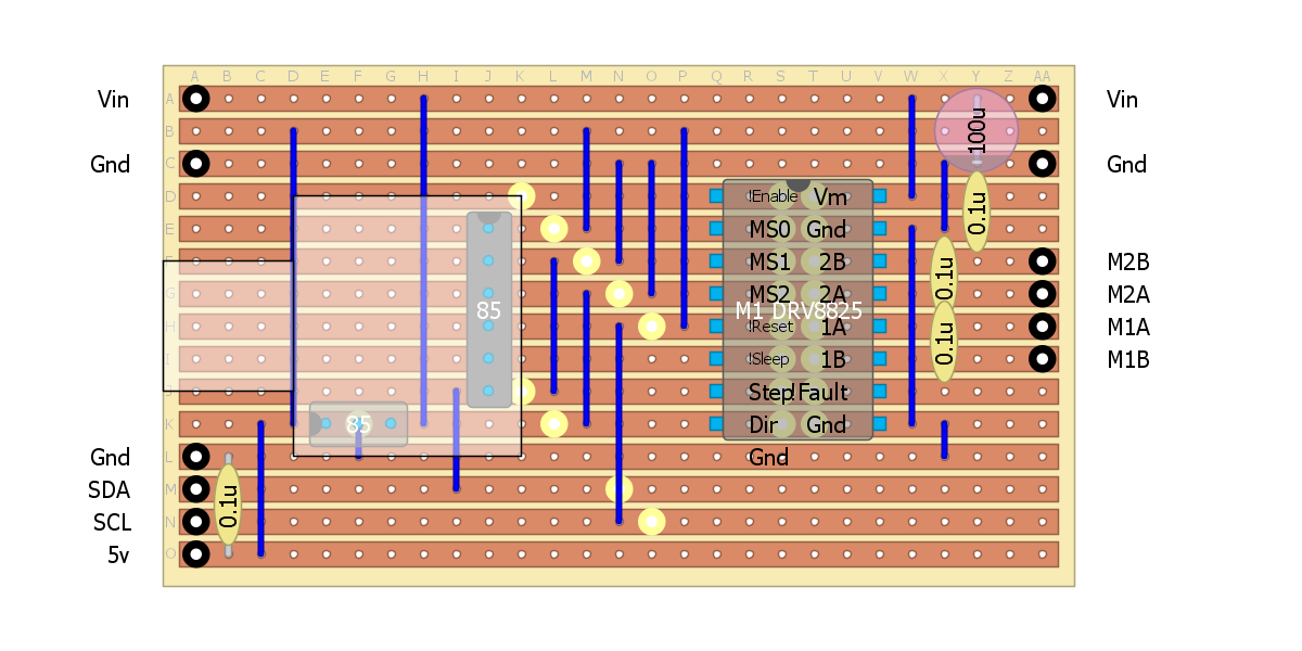
The idea is to place each I2C stepper driver board next to the motor to avoid interference to the other electronics.
I have played with the DigiSpark serial interface but it is not stable.
Here is the ultrasonic envelope detector transceiver board set up for I2C and Ping interface:
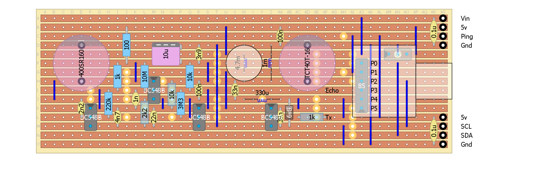
The above concept unfortunately will hear the 30 kHz stepper motor chopper frequency which I suspect was "the straw that broke the camel's back" that forced me to "surrender" (i.e. give up on making the Halloween deadline).
But really to begin should use HC-SR04 with a DigiSpark: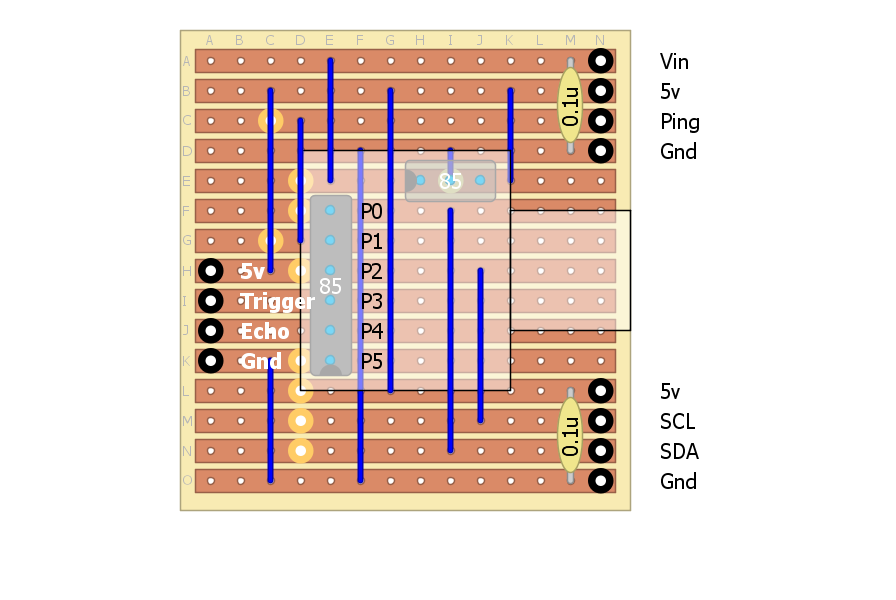
The problem with the servo solution is that scanning is too slow given the HC-SR04 can take more than 200 ms to time out. At least the ATTiny85 can hurry up the time out.
I2S cabling
I will have to find some suitable shielded cable to link up all the modules.
30 kHz Stepper Chopper Frequency
I suspect that on of the issue I was experiencing in addition to Inductive kick-back (back EMF) and Inductive current coupling was the stepper PWM frequency noise up setting the HC-SR04. Although HC-SR04 uses an active filter it is probably not sufficient to filter out enough of the chopper noise.
Checking schematics on the Internet of the HC-SR04 (that I have), the nearest match was (http://remotesmart.wikidot.com/esp202):
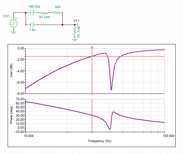
 Here is the response for the active filter (the IC2:C):
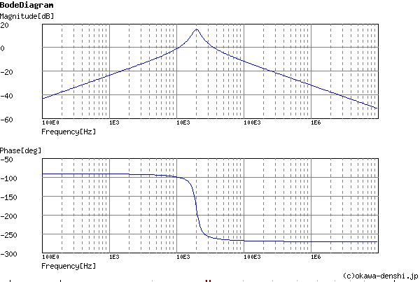
I can't read the capacitor values C2 and C3 so perhaps they are 500pF?
Others have confirmed the 20kHz centre frequency (http://uglyduck.ath.cx/ep/archive/2014/01/Making_a_better_HC_SR04_Echo_Locator.html) so I guess it is right.
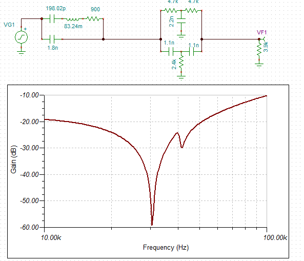
The sensor itself offers little out of band rejection (if you accept the equivalent circuit):
Here is the concept (rather than a design as the Q is too low):
Goertzel Again
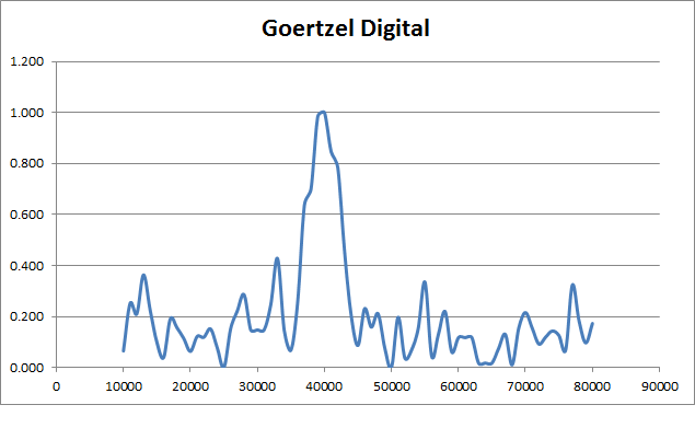
As the ATTiny ADC runs at 125 kHz it makes a good candidate for a Goertzel tone decoder.
Using 125 kHz sampling frequency and 25 samples (measuring 8 pulses at 40 kHz) here is what the frequency response looks like:
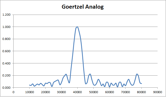
The band-width is 5 kHz (=125 kHz/25).
The side lopes are only -13 dB down.
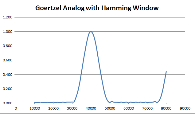
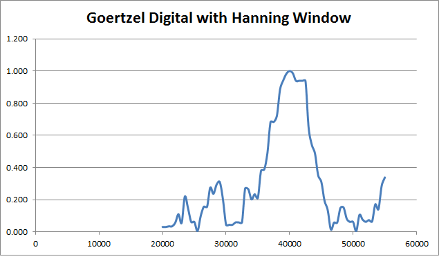
This can be improved by adding a "window" to the sample data (see http://www.mstarlabs.com/dsp/goertzel/goertzel.html) but at the cost of increasing the band-width:
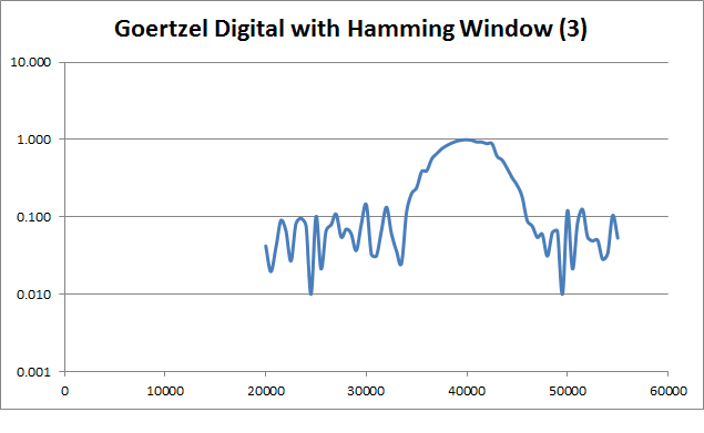
But does it work for pure digital data:
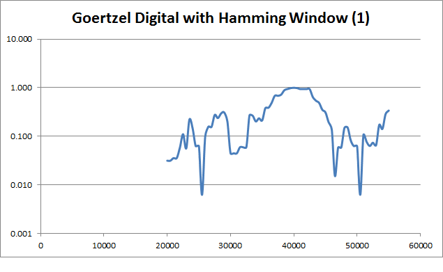
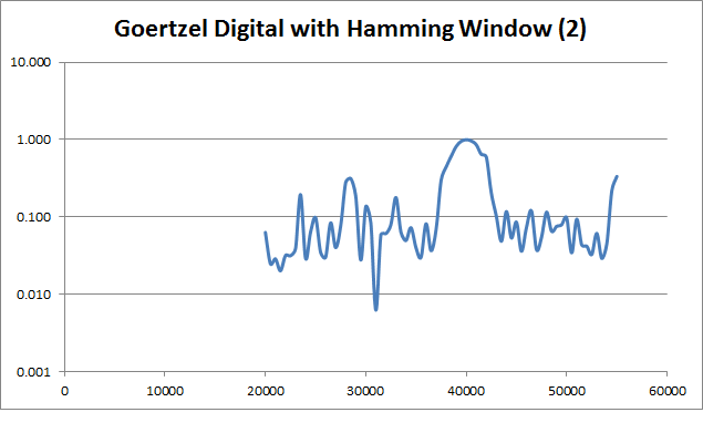
Here is the same window but with a log scale:
I tried using HP, Band Pass and Notch recursive IIR filters but with little success.
I am not sure why - could be coding errors or just not enough samples.
Here is the same setup but with twice the number of sample points (measuring 16 pulses):
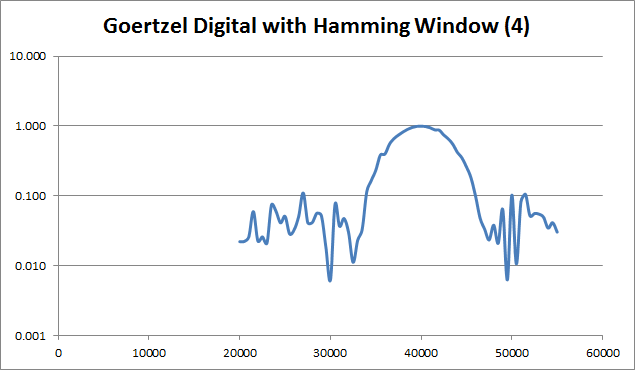
Here is the same setup but with twice the number of sample points and twice the sample frequency (250 kHz, measuring 8 pulses):
 Okay the noise floor has fallen.
And with 500 kHz sample frequency:
 And the noise floor as fallen again.
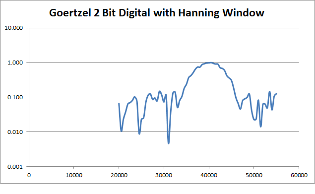
I even looked at a 2 bit binary (i.e. flash ADC) and that is approximately equal to doubling the sample frequency:
 Here is the original analog Goertzel using a log scale:
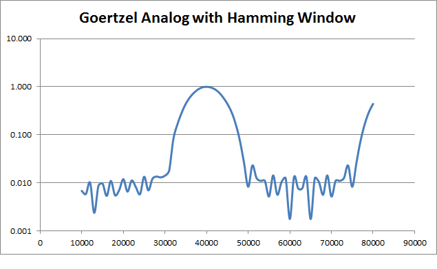 So it would appear that either a very fast digital read (>1 Mhz) or the analog read (=125 kHz on the ATTiny85) can work.
Rejection of the stepper motor 30 kHz PWM noise
The datasheet for the DRV8825 says 30 kHz (typical) but I need to measure it.
I also need to reduce the band-width a little, this means increasing the measurement period from 200 us (8 pulses) to say 250 us (10 pulse).
More if the PWM frequency is higher.
May also be worthwhile including a 30 kHz LC "trap" on the amplifier input.
AlanX
Discussions
Become a Hackaday.io Member
Create an account to leave a comment. Already have an account? Log In.