canning Sonar
Not a good day!
The old scanning sonar files are lost.
Okay start from scratch:
- Make a sonar scanner - done.
- Get a servo scanner working (took an hour or so to realise I forgot the common ground) - done.
- Get the HC-SR04 working - fail!
- Get a processing sketch to display the results - todo.
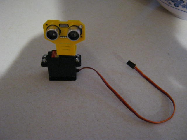
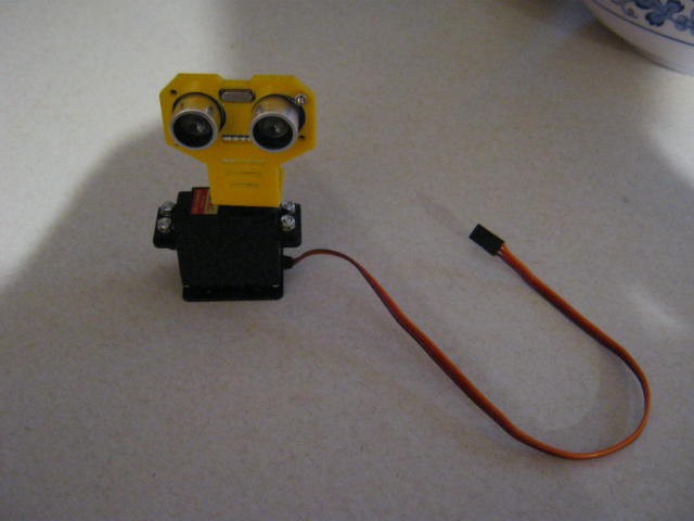
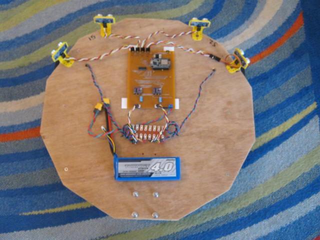
Here is the sonar scanner:
Could not get the sensor to work!
I had no problem a few days ago?
Tried three of them.
They would work if I touched them and then stop (you can hear them fire) when I move my hand away.
Changed to an Arduino Uno rather than a nano - same problem.
Use a power supply for the Uno.
All the sensor behave the same - cannot work it out.
Have I blown them up (my laptop USB has 35v AC on it - modern power supplies are all like this - unearthed)?
I will have to check if the trigger pulse is getting through with the oscilloscope (tomorrow).
Tomorrow is here
Relocated to my old desktop (it is earthed and less AC voltages on the metal surfaces).
Compiled NewPing and my version of sonar code.
Well the same problem (but not as bad).
The problem is the HC-SR04 stops working and usually (not always) needs to be powered down to reset.
The HC-SR04 fails if pointed into space (i.e. timeout) but can fail in other ways.
I have test three sensors and they all fail.
Fails for 50 ms and 1000 ms between triggers.
Checking with the oscilloscope, the trigger pulse for both the NewPing and my code is fine.
(The NewPing pulse threw me at first until I realised it was a trigger/echo signal.)
Added a 100uF to the Vcc and Gnd pins - no change - There was no real noise on the power supply or signal pins anyway (when using the desktop).
How does it fail? The Echo locks high!
There are schematics on the Internet that show the outputs are pulled high by a 10k resistor and controlled by a uP.
Emil's Projects (http://uglyduck.ath.cx/ep/archive/2014/01/Making_a_better_HC_SR04_Echo_Locator.html) has a pretty good description of the SHC-SR04.
Still I am puzzled? I did not have this out right failure when before.
It is as if they were damaged by the Dalek Test-Bed?
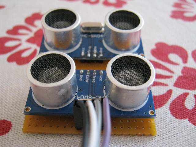
I only have one virgin sensor (that hs never been used on the Dalek Test-Bed) that I used for the twin sensor experiment (fail):
So I tested both (I left provision for this) and one sensor does not work but the other does.
I wonder which one has never been used on the Dalek Test-Bed!
The death statistics are five HC-SR04s, all from the Dalek Test-Bed!
Plausible Theory
Well it seems plausible that the Dalek Test-Bed (with the stepper motors) has damaged the HC-SR04s.
So high voltage inductive currents could be the reason(?).
But how? The HC-SR04s are feed from a 5v voltage regulator and each are decoupled with a 100n capacitor at the jumper.
The leads although twisted do pick up noise as a HC-SR04 with an extension (far right hand side) did not work (until the extension was removed):
How to fix?
I wish I knew what has failed on the HC-SR04?
I think I have taken enough precautions for the power supply (because it is an obvious problem area).
But I have not done much for the HC-SR04 inputs and outputs (a possible failure mode is from inductive currents?):
- A resistor (2.2k?) in series with the input and outputs to limit the MPU protection diode currents.
- Shield the HC-SR04 in a metal box.
- Use shielded the cables.
Just as well I order 10 more HC-SR04s.
Scanning Sonar
Scanning sonar up and running.
Usual problem of occassional zeros etc. but nothing like problems I have been having with the fixed sensors.
Emil's Projects (http://uglyduck.ath.cx/ep/archive/2014/01/Making_a_better_HC_SR04_Echo_Locator.html) suggests if is just crappy programming of the MPU.
So now I need some flexible shielded cable, a couple of current limit resistors and a metal box to mount the HC-SR04.
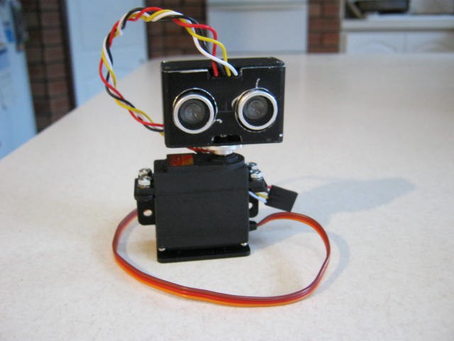
Here it is:
Pretty rough job but no time for perfection.
Inside the box is a strip-board with a protective circuity that should protect the HC-SR04 from any stray inductive currents.
I suppose I could stick a face on it.
Another Envelope Detector
My first (two transistor) receiver was a bit of a flop.
Basically the first transistor was upsetting the bias of the second transistor.
Here is another attempt but using a transistor detector instead of a schottky diode:
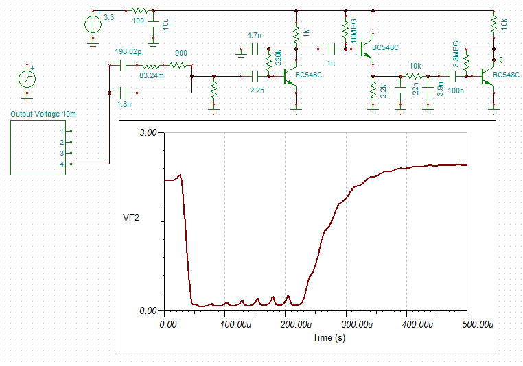
This time the second transistor is biased very low (just like a Class B amplifier).
The transistor output (no signal) is just 80 mv.
The gain (loss) at this operating point is very non-linear.
Here is the detector by itself (red input and green output):
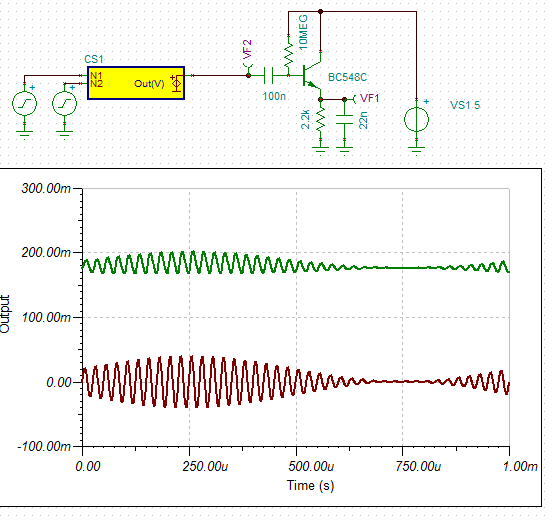
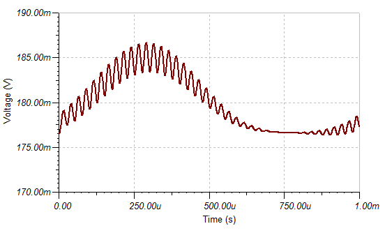
Adding a second low pass filter to the output brings out the detected modulation.
Sonar Scanner Software
I have some "PulseIn" code that will work with the PCF8574.
I just need to write the servo code.
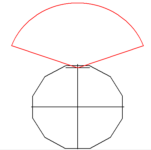
The range required is less than 40 cm (note that the servo cannot scan 180 degrees):
Updated Driver Board
Reworked the second last driver board for a servo output (red):
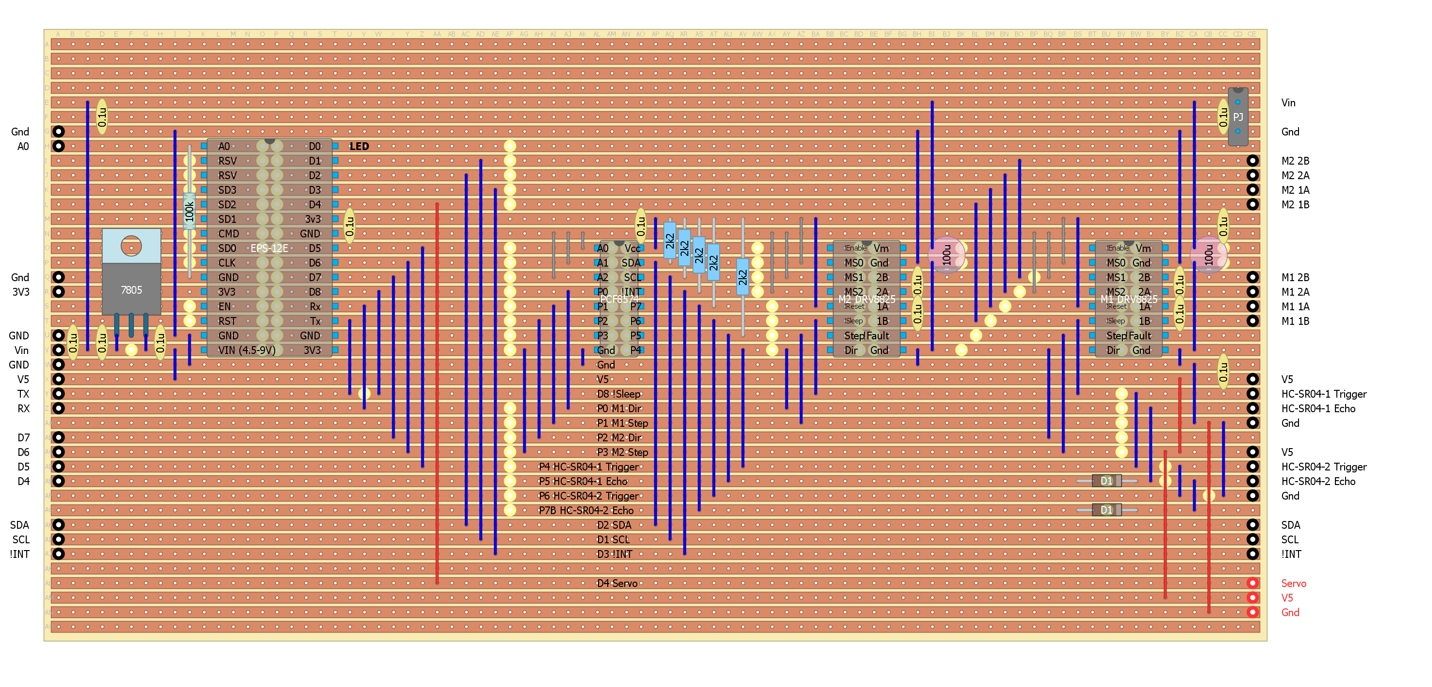
Bricked my last two HC-SR04s
I brick my last two HC-SR04 sensors.
Now I am shot (until the new ones arrive, a week away).
How did I do it?
This time I cannot blame inductive currents.
The sensor were working with the driver board until I added the servo motor.
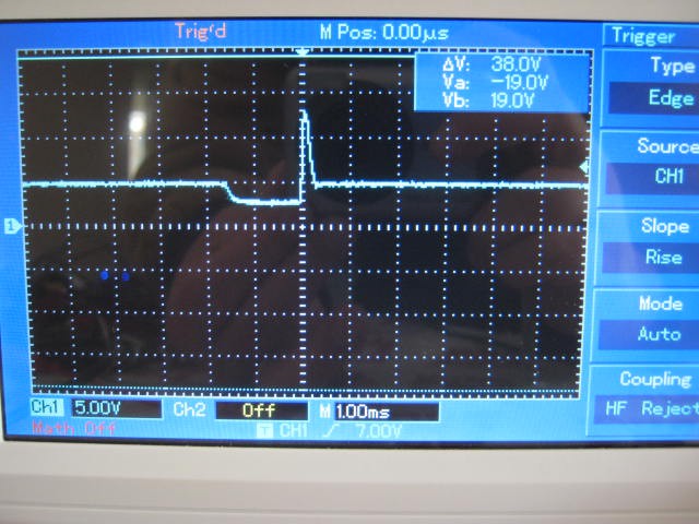
Checking the driver board I found a 13v spike on the 5v side of the 5v regulator:
Well that would be enough to take out the HC-SR04s (lucky it did not take out anything else).
There is 0.2 uF on the 5v side of the regulator, so I am surprised.
At least I know that it was over voltage that killed the the HC-SR04s.
The answer is a 6.8v zener diode across the Vcc and Gnd pins.
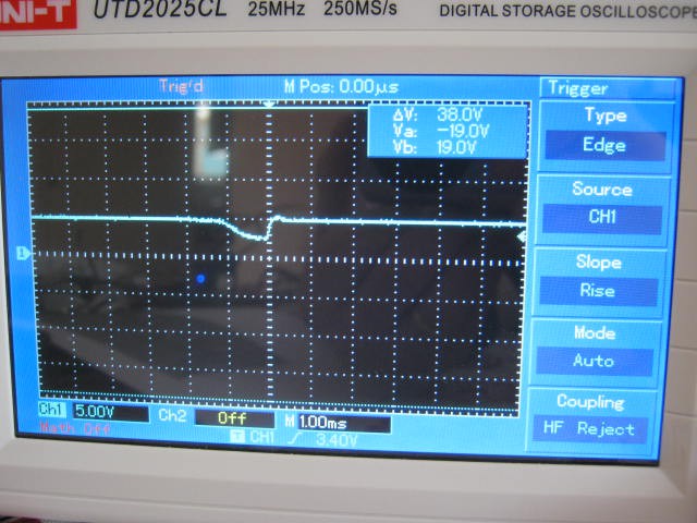
I added 100uF and it is still very disturbing:
It is pulling down the 5v supply to 2.5v for 1 ms!
Checking the Internet it seems that standard servos will pull about 5 A peak.
A 7805T will peak at 2.2A so no wonder that the 5v line was pulled down.
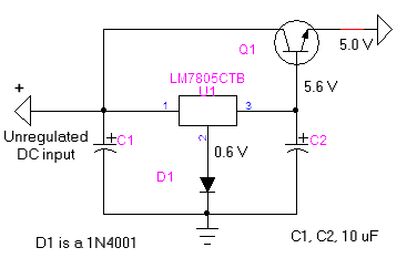
Here is a simple 5v regulated circuit that can sink more current:
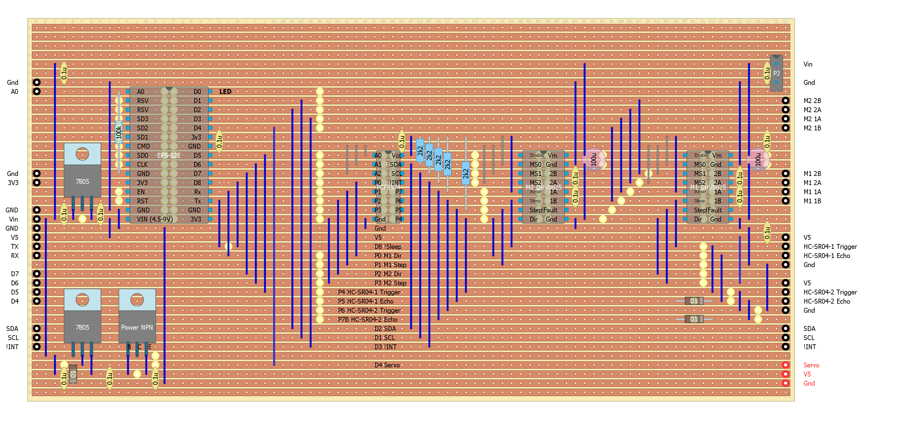
 Here is the updated driver board (with a separate power supply for the servo:
I think it may have been easier to use a stepper rather than a servo.
Partial Success
Added the servo regulator, works fine.
The problem now is that the servo sends an inductive voltage spike back to the transistors (I used two paralleled 2n5192).
As the transistors are rated at 80 volts that is pretty well what I was getting (I did not try and measure!) on the oscilloscope.
I added a 1W 6.2v zerer across servo power supply with no success(?)
I added a 1N4007 back to the battery and yes that limits the pulse to 13v and as this is a dedicated supply for the servos that should be okay.
Added a 100uF across the servo power supply, I now have a a long period (~30 ms) 8v peak.
Removed the zener - no change.
Good enough - move on:
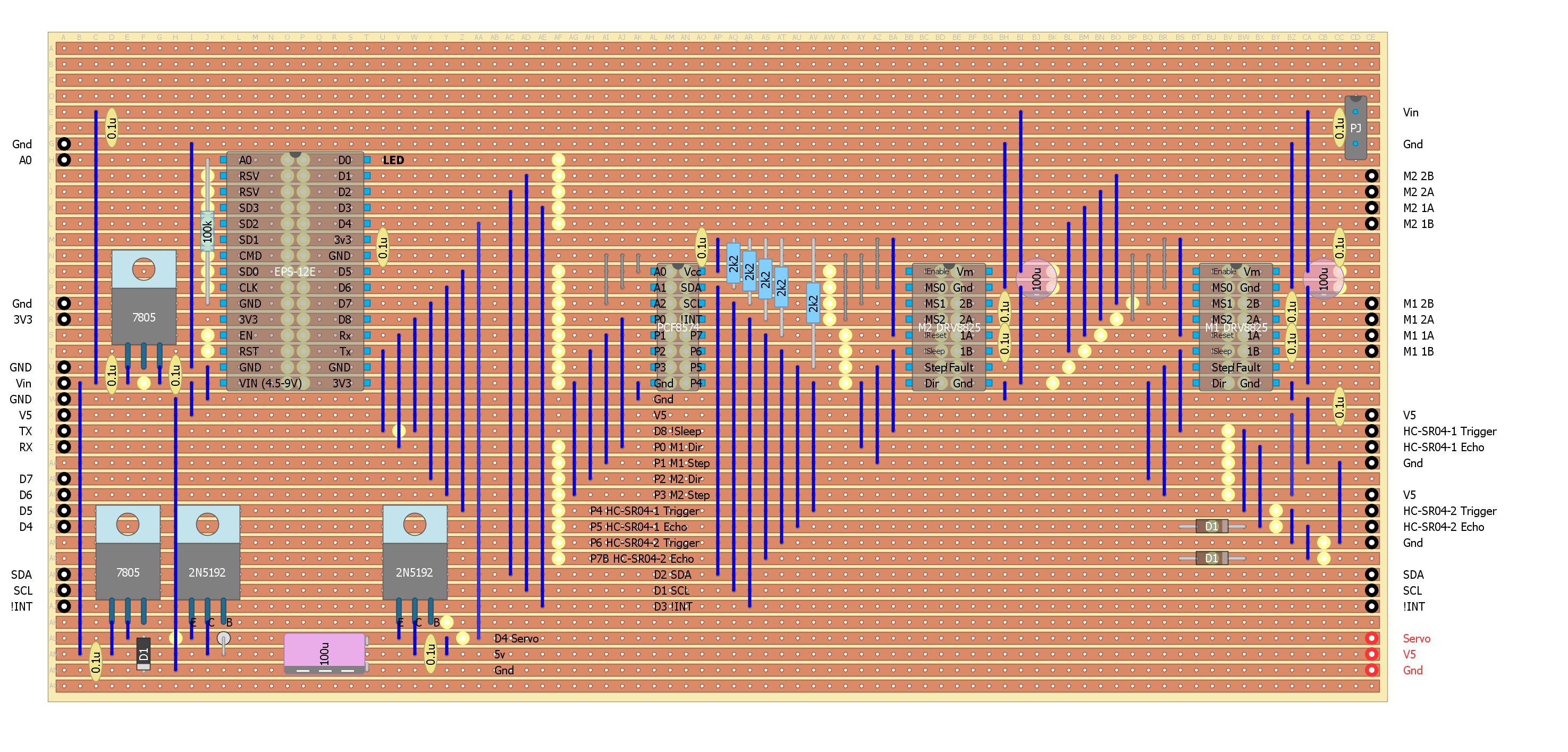
Servo Signal
The ESP-12E does have a servo library but working that with a HC-SR04 DIY "PulseIn()" via a PCF8574 is a bit problematic.
The servo signal on the oscilloscope misses lots of pulses.
Even the stand alone sweep sketch suffers these problems.
Part of my problems were due to:
- Avoiding the use of the EPS-12E timer (as there is little documentation).
- Using the PCF8574 instead of multiple slave processors (i.e. ATTiny85).
The ESP8266 servo library seems to use polling as delay() kills it.
I decided to have a look at the ESP Timer system, there are a couple of worked examples on the Internet.
Here is my version (of sweep), pretty simple really:
#define servoPin D4
volatile int servoPulse=0;
volatile int servoAngle=90;
volatile unsigned long next;
void inline servoISR(void){
  if (servoPulse==0) {
    next=next+40000+889*servoAngle;
  } else {
    next=next+1560000-889*servoAngle;
  }
  timer0_write(next);
  servoPulse=1-servoPulse;
  digitalWrite(servoPin,servoPulse);
}

void setup()
{
  // Servo initialisation (uses D4)
  pinMode(servoPin,OUTPUT);
  noInterrupts();
  timer0_isr_init();
  timer0_attachInterrupt(servoISR);
  next=ESP.getCycleCount()+1000;
  timer0_write(next);
  interrupts();
  // Serial.begin(9600);
  // Serial.println();
}

void loop()
{
  const int minAngle=16;
  const int maxAngle=176;
  const int midAngle=96;
  static int servoDir=1;

  delay(50);
  // Next position
  if (servoAngle>maxAngle) servoAngle=maxAngle;
  if (servoAngle<minAngle) servoAngle=minAngle;
  if (servoAngle==maxAngle) servoDir=-servoDir;
  if (servoAngle==minAngle) servoDir=-servoDir;
  servoAngle+=servoDir;
  // Serial.println(servoAngle);
}
The new HC-SR04s have arrived
I hooked up the orignal version of the scanning sonar:
  if (servoPulse==0) {
    next=next+40000+889*servoAngle;
  } else {
    next=next+1560000-889*servoAngle;
  }
The Internet has a lot of incorrect numbers for servos.
The range for this servo (0 to 180 degrees) is 0.5 ms to 2.5 ms.
Protecting the HC-SR04
I seems reasonable that over voltage on the HC-SR04 power supply is what killed it.
I think probably kills the voltage multiplier (i.e the ST232CD?).
For the servo, a 100uF power supply capacitor tamed the inductive voltage spike.
So this is the way I will go (I was disappointed with the performance of the 1W 6.2v zener - probably a 5A peak current was a bit of an ask!).
Here is the proposed HC-SR04 protection board:
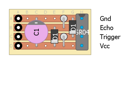
I will solder it to the base of the HC-SR04.
Zener Diode
I was not real happy with the zener not working.
So as a test I put a 5.1v 1W zener across the servo power supply.
Worked fantasic!
Checked the zener voltage (5.03v) and current (10mA), so great.
Just to be sure I swapped the 7805 voltage reference diode (1n4148) with a schottky diode (bat41).
The regulator voltage is now 4.93v so all should be good for the servo power supply.
Added a 6v8 400mW zener (all I had) across the power supply of the HC-SR04 protection board.
AlanX
 agp.cooper
Discussions
Become a Hackaday.io Member
Create an account to leave a comment. Already have an account? Log In.